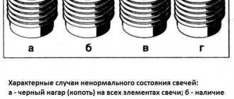
We repair the ignition switch on a Shevik. Try to remove it first))
Another breakdown has come, apparently I drove for a year without any breakdowns and that’s enough - my Shevik decided.
Suddenly the key is blocked in the ignition, it is put in the first position (ignition), but the key does not turn to the second (starter), for the life of me. I read the forums, this breakdown is quite common in the Chevrolet Niva, but I couldn’t find a proper manual anywhere, so I had to rack my brains myself right on the spot, that is, with my head under the steering column)) I immediately decided to record everything with photos and videos, so now it will be easier for you.
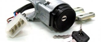
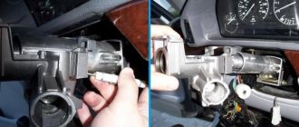
Apparently, having removed the casing from the steering column (there are 5-6 bolts on all sides and a rubber round coupling around the lock), we see the following - the lock itself is attached to the column using an additional bracket (on the left), which is attached to the lock mount itself with powerful and hemorrhagic tear-off bolts.
In general, the biggest problem, and not only for me, is to remove this damn ignition switch from the steering column. It is secured with 4 breakaway bolts, which are specifically designed to make it more difficult to steal a car.
Therefore, if you are not going to repair the lock itself, but simply decided to replace it, then do not forget to buy 4 tear-off bolts!
That is, they are easy to tighten; the caps have hexagonal key heads, which, at a certain tightening torque, break and a round cap remains. This is what we will need to unscrew, as many as 4 pieces. It turns out that putting it on is easy, but taking it off is difficult. And this is the true truth, believe me. For some it will take 10 minutes, for others it will take 2 hours, and they can’t remove it, but simply cut off the bolts with a chisel.
Here they are in the photo:
To unscrew them, we need a small chisel and a hammer, as well as a 5 mm flat screwdriver, preferably longer.
We unscrew it COUNTER-clockwise, adjust the chisel so that the angle of inclination is sharper, so that the force of the blow goes sideways, and not directly into the head. And we try to make a notch on the head of the breakaway bolt with a chisel; the most important thing here is to remove the bolt from the thread so that, once stuck, it begins to move.
In this way, moving the chisel, punching 3-4 mm at a time, we turn the bolt to the left until it loosens. Then you can unscrew it with your fingers or pliers if it still doesn’t turn well.
This is what such a bolt looks like, it goes to the cone. Let's take on the second one.
The most difficult one will be the one on the top right, it will be very difficult to crawl there, and then try to make a notch with a chisel, and then use a long flat screwdriver to rest against this notch and gently tap. Place the screwdriver at a “sharper” angle to the head so that the blow is kind of sliding, but also catches slightly.
By the way, we also shot a video on the third bolt, inspired by the success. Take a look, I think it will become clear how to unscrew them. Sorry, my friend’s hands are shaking, but the essence is still clear, it is described above))
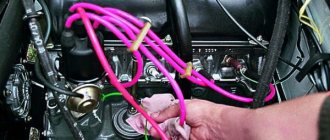
Having unscrewed the bolts, you have practically won, now you can replace the lock itself without any problems, everything is quite simple, you disconnect 4 wires - red, blue, pink and black. True, you will also have to unscrew the lock itself from the second part of the fastening - using a Phillips screwdriver, 3 bolts.
There is a steering column locking stop in the center!
By unscrewing these 3 bolts, you can disconnect the ignition switch from the fasteners or (in our case) you can remove the “cylinder” of the lock and thereby repair it.
A lock without a key looks like this - stoppers stick out in all directions, which catch when turning and thus prevent the cylinder from turning inside.
When you insert the key into the cylinder, all the pins should be removed, thus they will not interfere with the key turning. In our case, we had 1 pin sticking out on the left, which clung and did not allow the “larva” to spin. We worked on it with a file.
Also carefully inspect the lock cylinder; it is quite possible that you will see burrs and even grooves on the upper side that were “trodden down” by the pressure pin running along its top. It turned out that for all the time (and the car is already 10 years old), he made his own move in the “body of the larva” (outer side), which ended in a dead end. And in this position the key was locked (position I - ignition). There, they also used a needle file to grind off the furrow it made; make the angle as sharp as possible. It is very difficult to explain, so think about how and what should work. The lock cylinder is made of soft material and in 10 years it will definitely wear out, the rear round pin “drills” its path. Point it the right way and you won't have to buy a new ignition switch.
For those who would be more interested in repairing the lock themselves, you can watch another short video on how to get the cylinder.
Oh yes, you can find locks with cylinders on sale (3 pieces - for the front doors and trunk) - the cost is about 1,300 rubles.
Or take it without the cylinders - it costs 900 rubles, but now you will have 2 keys - one to start the car, and the second to close/open the front doors and trunk. So repairing the lock, in my opinion, is a very good option, you win in 2 categories at once - you save money, and you will still have 1 key for everything, as before.
Electrical diagram of VAZ-21214M 2011
ELECTRICAL CONNECTION DIAGRAM FOR FRONT WIRING HARNESS 21214-3724010-44
- 1 — right headlight;
- 2 - starter relay;
- 3 — front harness block to the instrument panel harness block;
- 4 — air temperature sensor;
- 5 — coolant temperature sensor;
- 6 — oil pressure warning lamp sensor;
- 7 — sound signal VAZ-21214;
- 8 — brake fluid level sensor;
- 9 — left headlight;
- 10 — pads for the front harness, sidelight harness and side turn signal
- right;
- 11 — pads of the front windshield wiper motor harness and electric motor;
- 12 — electric motor of the windshield wiper;
- 13 — blocks of the front harness and connecting starter wire;
- 14 — starter;
- 15 — rechargeable battery;
- 16 - generator;
- 17 — front harness block and connecting generator wire;
- 18 — right side turn signal;
- 19 — right sidelight;
- 20 — electric motor for washers;
- 21 — pads for the front harness, sidelight harness and side turn signal
- left;
- 22 — left sidelight;
- 23 — left side turn signal.
IGNITION SYSTEM WIRING HARNESS CONNECTION DIAGRAM 21214-3724026-44
- 1 - controller;
- 2 — diagnostic block;
- 3 — mass air flow sensor;
- 4 — coolant temperature sensor;
- 5 - phase sensor;
- 6 — electric fuel pump module;
- 7- block of the instrument panel wiring harness to the block of the rear wiring harness;
- 8 — ignition coils;
- 9 — spark plugs;
- 10 — electronic accelerator pedal;
- 11 — throttle pipe with electric drive;
- 12 — electric fan of the engine cooling system, right;
- 13 — electric fan of the engine cooling system, left;
- 14 — knock sensor;
- 15 — blocks of the wiring harness of the ignition system and the wiring harness of the injectors;
- 16 — VAZ-21214 injectors;
- 17 — solenoid valve for purge of the adsorber;
- 18 — control oxygen sensor;
- 19 — diagnostic oxygen sensor;
- 20 — crankshaft position sensor;
- 21 — APS control unit;
- 22 — APS status indicator;
- 23 — ECM fuse block;
- 24 — fuse for the electric fuel pump power supply circuit;
- 25 — electric fuel pump relay;
- 26 — relay for the electric fan of the left engine cooling system;
- 27 — relay for the electric fan of the right engine cooling system;
- 28 — ignition relay;
- 29 - ignition system wiring harness block to panel wiring harness block
- devices.
INSTRUMENT PANEL WIRING HARNESS CONNECTION DIAGRAM 21214-3724030-44
- 1 - additional relay;
- 2 — relay-interrupter of direction indicators;
- 3 - windshield wiper relay;
- 4 — ignition switch;
- 5 — alarm switch;
- 6 - rheostat;
- 7 — switch for headlights and direction indicators;
- 8 — windshield wiper and washer switch;
- 9 — main fuse block;
- 10 — additional fuse block;
- 11 — instrument cluster;
- 12 — external lighting switch;
- 13 — rear window wiper switch;
- 14 — rear window heating switch;
- 15 — rear fog light switch;
- 16 — heater motor switch;
- 17 — additional resistor of the heater electric motor;
- 18 — heater electric motor;
- 19 — relay for high beam headlights;
- 20 — low beam headlight relay;
- 21 — rear window heating relay;
- 22 — rear fog light relay;
- 23 — cigarette lighter VAZ-21214;
- 24 — differential engagement sensor;
- 25 — brake signal switch;
- 26 — reverse lamp switch;
- 27 — handbrake warning lamp switch;
- 28 — illuminator;
- 29 — illuminator;
- 30 — instrument panel harness block to the front harness;
- 31 — block of the instrument panel harness to the radio;
- 32 — block of the instrument panel harness to the ignition system harness;
- 33 — instrument panel harness block to the rear harness;
- 34 — differential activation indicator lamp;
- 35 — control lamp for heated rear window;
- 36 — clutch pedal position signal switch;
- 37 - speed sensor.
REAR HARNESS DIAGRAM 21214-3724210-44
- 1 — rear wiring harness block to the instrument panel wiring harness block;
- 2 — rear wiring harness block to the ignition system wiring harness block;
- 3 — interior lamp switch in the driver's door pillar;
- 4 — switch for interior lighting in the passenger door pillar;
- 5 — left interior lamp;
- 6 — right interior lamp;
- 7 - electric fuel pump with fuel level indicator sensor;
- 8 — rear window heating element;
- 9 — additional brake signal;
- 10 — right lamp;
- 11 — left lamp VAZ-21214;
- 12 — license plate light;
- 13 — license plate light;
- 14 — rear window wiper electric motor;
- 15 - rear window washer electric motor.
Currently, problems with a car’s electrical system can be corrected at any car service center, but for those who like to fix everything themselves, an electrical circuit will come in handy. The electrical diagram of a VAZ 21214 with an injection engine is a graphical representation that shows the order and connection of the elements in the circuit, but does not show the actual arrangement of the elements. But even the most inexperienced car enthusiast will be able to understand something in the electrical circuit of the VAZ 21214 and fix a small malfunction on his own, which will help save time and money.
Symptoms of a problem
The wheel bearing is the most vulnerable part and the easiest to diagnose. A number of signs are determined even without disassembling the car. You can feel them while driving.
Vibration in the front wheels. This does not require observation from the outside. Vibrations can be felt in the cabin as a slight shaking of the steering wheel. Sometimes the bearing wear is so severe that the entire interior can vibrate.
1. Knock. The wheel bearing of a Chevrolet Niva can manifest itself in the form of a knocking sound in the front part of the car. If when driving, the front part makes noise, then everything is diagnosed while driving.
2. Heating. When the bearings fail, the wheel begins to move to the sides. Because of this, the friction area increases and the axle heats up. If after a trip the central part is very hot, the Chevrolet Niva Niva front wheel bearing needs to be repaired or replaced.
Features of the modification
First of all, the changes affected the engine management system and control instruments. In particular:
- The wiring diagram for Niva 21213 received an additional wiring harness in the engine compartment for connecting a microcontroller and sensors;
- On the Niva model of recent years of production, a more advanced power unit with the VAZ-21214 index is installed. Instead of a carburetor, it has a fuel frame with injectors from GM. The price of a car with injection has increased because of this;
- The instrument panel has changed - the design is borrowed from the VAZ 2108 model.
Unification of the instrument panel: LADA NIVA with a panel from VAZ 2108
Ignition system
The VAZ 21213 engine uses a non-contact ignition system consisting of:
- ignition distributor sensor (marking 3810.3706). It is responsible for creating control pulses supplied to the electronic switch;
- switch (model marking – 3620.3734) in climatic version U2.1 (corresponds to GOST 15150);
- ignition coils (marking 27.3705).
Electronic switch for VAZ 21213
Dashboard
A modified instrument panel appeared on the car. In particular, instead of a voltmeter, the manufacturer installed a low battery discharge lamp (no. 12 in the diagram).
Connection diagram of warning lamps and devices VAZ 21213 1997 onwards.
Pinout of the ignition switch VAZ 2101 VAZ 2107
The system in these versions is located to the left of the steering wheel. To protect against dust and burglary, it is closed with a special plastic cover.
The pinout of the ignition switch of the VAZ 2107 will allow you to notice special marks that you need to focus on during repairs. They have the following purposes:
1. "". The absence of a mark indicates that all systems are currently turned off and not working. These devices do not include brake lights, lighting, cigarette lighters and, in some models, radios.
2. "I". This position indicates a working battery, as well as the inclusion of a number of automotive equipment, such as windshield washers, headlights and some alarm functions.
3. "II". A position indicating the start of the motor system. It does not have a key lock, as there is likely to be an increased load on the starter.
4. "III". Parking mark. When the key is pulled out, it locks. To remove the block, you need to insert a key.
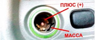
The lock has 5 contacts. An ignition switch wiring diagram is required in order to understand the general purpose of each of them. All of them are marked with numbers and letters:
1. 50. Red or purple wire. Supplies voltage to the starter.
2. 15. Two-core wire with blue insulation and black stripes. Supplies current to the cigarette lighter, washer, and brake light.
3. 30 and 30/1. Pink or brown positive contact.
4. INT. Two-core black wire responsible for headlights and light signaling.
The ignition switch connection diagram gives an idea of the work plan and will allow you to independently diagnose and identify problems in the system. The VAZ ignition switch is convenient and easy to disassemble.
The ignition switch pinout may be erased. If such a defect is allowed, you can match the lock with the picture.
Which ignition is better: contactless or contact?
The carburetor circuit also includes: a drive lever from the accelerator pump, a diaphragm, an adjusting screw and an air duct from the starter, a shut-off valve (solenoid), an air damper, a needle valve, a fuel supply fitting, an economizer for power modes, a carburetor heating unit, fittings for crankcase ventilation, for supplying vacuum for the vacuum regulator in the ignition, and other elements.
How to remove the ignition switch on a classic
Niva 2121 has the following sequence of passage of fuel elements through the carburetor chamber. First, fuel moves from the fuel tank to the float chamber in a controlled amount. The float rises or falls as the fuel moves.
Further, the fuel path lies through the nozzle into the atomizer, located in the narrow part of the diffuser, with simultaneous air entering the carburetor through the outer pipe. The throttle valves then deliver varying amounts of fuel into the engine cylinder through an intake manifold cast from aluminum alloys. The manifold is attached to the engine with studs through gaskets that have heat-resistant properties.
| №1 | Ignition relay |
| №2 | Main relay |
| №3 | Right cooling fan relay |
| №4 | Left cooling fan relay |
| №5 | Fuel pump relay (fuel) |
| №6 | Fuel pump fuse F5, 15A |
You can roughly assess the serviceability of the vacuum regulator directly on the car. With the engine running, disconnect the vacuum hose leading to the regulator from the carburetor fitting.
If you now create a vacuum in the hose (you can use your mouth), the engine speed should increase, and when the vacuum is removed, it should decrease again.
The vacuum should remain for at least a few seconds if the hose is pinched.
Also interesting: How to connect a speed sensor in a field
You can visually verify the functionality of the vacuum regulator by partially disassembling the distributor sensor (see Repairing the ignition distributor sensor of a VAZ-2121 car) and applying a vacuum to the inlet fitting of the regulator.
If the vacuum regulator fails, it should be replaced; if the centrifugal regulator fails, the sensor-distributor should be replaced.
The switch - type 3620.3734, or HIM-52, or VAT10.2, or 76.3734, or RT1903, or PZE4022 - opens the power circuit of the primary winding of the ignition coil, converting the control pulses of the sensor into current pulses in the ignition coil.
Replacing the ignition switch and its contact group
The switch is checked with an oscilloscope using a special method and is not repairable; If a malfunction is suspected, it is recommended to replace it.
Ignition coil - type 27.3705 or 27.3705-01, or 8352.12, or ATE1721 - oil-filled, with an open magnetic circuit.
Data for verification: resistance of the primary winding at 25°C – (0.45±0.05) Ohm, secondary winding – (5.0±0.5) kOhm. Insulation resistance to ground is at least 50 MOhm.
Replacing the coil and commutator is described in the article - “Replacing the coil and commutator”
Spark plugs - type A17DVR or A17DVRM, or A17DVRM1, or their imported analogues (with noise suppression resistors with a resistance of 4–10 kOhm). The gap between the electrodes is 0.7–0.8 mm.
High-voltage wires – with distributed resistance (2550±270) Ohm/m.
It is also prohibited to start the engine or allow it to operate with an open high-voltage circuit (removed wires or the distributor sensor cover) - this can lead to burnout of the insulation and failure of the electronic components of the ignition system.
As an exception, a short-term check of the ignition system “for spark” is allowed, and the contact of the high-voltage wire being tested must be securely fixed at a distance of 8–10 mm from the vehicle ground.
Do not hold the wire with your hands or tools (even with insulated handles).
Design features and self-repair of the ignition switch of the VAZ 2101
Ignition switch - type 2101-3704000-11, with anti-theft locking device.
When the key is turned to the “ignition” position, voltage is supplied to the control input of the additional relay, which, in turn, supplies voltage to the ignition coil and switch.
Chevrolet Niva hub - replacement
To replace the wheel bearing in the field, you need to pull out the hub. This is carried out according to the following plan.
1. Dismounting the conical bushing.
2. Unlocking the nuts. The problem may lie in the fact that they often lick off or turn sour. In this case, you can use a chisel and a light hammer.
3. Use the nineteenth socket or wrench to remove the lever clamps. They are located both front and back.
4. The locking plates are removed. These are metal perforated strips that are often overlooked.
5. The seventeenth and tenth keys require removing the circuit pipes.
6. A stop is installed under the lever. Using two twelfths keys, unscrew the nut fixed on the upper arm retainer bolt.
7. The lower block is also unscrewed in the same way.
8. When there are no fasteners left, it is possible to pull out the entire system at once.
9. By fixing the steering knuckle with a clamp, you can knock out the hub.
10. After this, the screws securing the knuckle to the lever mechanism are removed.
Knowing the structure of the front wheel hub of Niva 21213, you can carry out repairs yourself, without contacting a service center.
How to check the ignition module?
After installing and connecting all components, you need to diagnose the functionality of the module:
- First, the resistance between the terminals of the secondary winding is measured - the probes are connected to cylinders 1 and 4, and then to 2 and 3. The indicators can be any, the main thing is that they more or less coincide. A malfunction of the secondary winding will be indicated by an error in the indicators of more than 100 Ohms.
- After this, you need to test the wiring; to do this, you need to disconnect the block from the unit and set the multimeter to voltmeter mode, with one tester probe connected to pin A, and the second to ground. Start the engine and watch the tester display - the readings should be about 12 volts, the second contact is diagnosed in the same way.
- If there is no voltage, you should diagnose the safety element located in the mounting block under the center console. The reason for the lack of voltage can be not only a blown fuse, but also poor contact, broken wiring, as well as corrosion (author - AutoElectrika Diary channel).
Adjusting the wheel bearing Pulls and adjustment
You will need a clock type indicator. When installing, its leg should rest against the adjustment nut. A lever made from a hairpin smoothly rotates the mechanism around its axis. If the gap is more than 0.15 millimeters, the nut requires replacement.
Replacing the ignition switch on a VAZ car
The above diagram of the ignition switch for the VAZ 2107 will make it easier to replace. It is carried out according to the following plan:
· The plastic casing is dismantled;
· Remove the screws securing the bracket;
· The key is placed in position “0”;
· An awl or needle is inserted into the groove and the latch is snapped off.
The ignition switch circuit of the VAZ 2107 may differ slightly if non-original components were previously installed.
We carry out the adjustment ourselves
- The first step is to install the cylinder in the correct position. Installation is carried out so that the mark on the pulley is exactly at 0 degrees.
- Set how the slider is positioned. It should be aimed at the first pin in the cylinder.
- Use a strobe light and make sure the ignition is working properly.
- Make the electrical connections in the battery: minus to ground, plus to plus.
- The sensor must be connected to the high-voltage wire on the cylinder. The mark should connect to the crankshaft pulley.
- Start the engine at low speed (up to 800 rpm). Use a stroboscope to illuminate the pulley, and if the mark coincides with the middle mark, then the ignition is set correctly.
- Otherwise, the engine should be turned off and the meter should be loosened. In order to decrease the angle, turn the sensor clockwise; to increase it, turn it counterclockwise. Record and test the calibration again with the ignition on.
- Next, you should perform manipulations with the distribution sensor. Open the lid. Match the stator and rotor mark.
- Start the engine, bring the temperature to 75-80 degrees. When the speed is 50 km/h, sharply press the gas pedal.
- If the ignition was installed correctly, a short-term detonation will occur when you press the gas.
Also interesting: Phase sensor Niva Chevrolet symptoms of malfunction, DPRV high signal level
Then there are two possible developments: early and late ignition. Let's consider solutions for both cases:
- In the case of late ignition, when there is no detonation, you should change the position of the sensor clockwise.
- In the case of early ignition, when detonation lasts longer than necessary, the sensor is rotated counterclockwise.
Niva 21213 can be subject to adjustment of the starting system by the gap at the edges of the valves, if the carburetor is removed, or by the crankshaft speed directly on the car. In the first case, the gap at the location of the lower edge (in the direction of air movement) from the throttle valve is set to a width of 1.1 mm.
It is adjusted with a screw that has a 0.7 cm hexagon on the head and a slot from the shank. This operation is carried out with the cam lever turned counterclockwise from the starting system control (all the way). In the same position, the gap at the lower edge of the air damper is set to 3 mm using a screw in the cover from the diaphragm mechanism in the starting system (you need to loosen the lock nut).
The principle of powering a carburetor engine Adjusting the Niva starting system directly in the car saves time: You need to remove the air filter from the engine, pull the control lever towards you from the air damper, and start the engine. When the air damper is forced to open (by touching a flat screwdriver to a third of its full angle of rotation) using a screw (next to the lever on the axis from the throttle valve from the first chamber), the initial rotation speed is set to 2.08.mar.0 thousand.
revolutions per minute (on a warm engine). Remove the screwdriver, lower the air damper and, using the screw stop (next to the diaphragm), set the frequency to be 100 rpm lower than the original one (you need to select the appropriate position of the air damper). The screw can then be secured using a locknut.
If you have a gas analyzer, then the carburetor adjustment in the starting system part can be done based on the amount of CO (carbon monoxide) in the exhaust gases. If, with the choke control lever fully extended, the gas rate is 8%, then everything is in order. If there is less gas than this value, then the screw on the cover of the diaphragm mechanism is tightened; if there is more, it is unscrewed and repeated measurements are taken.
Features of replacing the ignition switch in a Chevrolet Niva: how to change it yourself
The ignition switch of the Chevrolet Niva cannot be called its weak point - as a rule, it serves for ten years without problems. However, over time, it can still begin to act up, since its larva is made of soft metal and is subject to simple physical wear and tear.
Replacing the ignition switch of a Niva Chevrolet does not require special knowledge and skills, so the car owner can handle it himself. The main thing you need when dismantling an old lock and installing a new one is patience, since the procedure itself is simple, but quite labor-intensive and time-consuming.
Disassembly process
Having removed the lock from its seat in order to replace it later, you can pay attention to the wiring. First, unscrew a couple of bolts with a Phillips screwdriver. They hold the block with wires.
We remove the cylinder from the dismantled lock, visually checking for damage. There are small stoppers around the bronze cylinder that prevent turning without a key. Some of them may be damaged. Repairing the Chevrolet Niva ignition switch may not always be appropriate, since the damage may be beyond repair.
Sometimes the resulting nicks are visible and can be corrected with a small file. Excessively large portions should not be removed, as this may lead to loss of performance of the larva. If there are no recovery options, you will have to install a new lock in the assembly.
Signs that it’s time to change the ignition switch
Early signs of a malfunction in the Chevrolet Niva ignition switch usually manifest themselves in the key jamming when it is turned in the cell. Slight jamming is especially common when turning the key from the “Ignition” position to the “Starter” position. Over time, the malfunction progresses and can lead to the key jamming in the cylinder.
At first, this problem can be solved by disassembling the lock and dripping oil into the cylinder, thereby reducing friction in it when turning the key. However, if the jamming progresses, then it is better to replace the lock before its cell jams tightly.
The presence of problems with the ignition switch is also indicated by the key slipping in the cylinder when it cannot be turned to the “Ignition” or “Starter” position. This situation also indicates a breakdown of the larva.
The second group of faults is related to the contact group. The Chevrolet Niva ignition switch is powered by several groups of energy consumers:
- in position “0” the car’s side lights can be turned on;
- in position “1” (“Ignition”) the high and low beams, turn signals and tail lights, the fuel pump, power windows, wipers, etc. work;
- in position “2” the starter starts.
In the case when several energy consumers, seemingly unrelated to each other at first glance, stop working, the problem may lie in a break, breakdown, or oxidation of the contact.
Such a malfunction does not necessarily require replacing the lock - you can repair the contact group by replacing damaged contacts. However, a problem with the contact group may indicate general wear and tear of the lock, so it is better to replace it entirely.
conclusions
The modification of the VAZ 21213 Niva car undoubtedly benefited him. The new engine and improved ignition system have made its operation even easier and more confident in harsh conditions.
| Electrical equipmentFuses and relaysElectrical circuitsConnector diagramsEngine compartment wiringDashboard wiringWiring of the middle and rear partWiring of doors and tailgateRemoving the fuse boxGeneratorGenerator malfunctionsRemoving (replacing) the generatorRepairing the generatorStarterStarter malfunctionsRemoving (replacing) the starterRepairing the starterIgnition switchReplacing the ignition moduleReplacing spark plugsEngine management system Fault codesReplacing fuses and relays - engine management systemReplacing the controllerReplacing the crankshaft sensorReplacing the cooling sensor fluidReplacement of the throttle sensorReplacement of the MAF sensorReplacement of the knock sensorReplacement of the oxygen sensorReplacement of the speed sensorLighting and alarm breakdownsLighting diagramsWorking of the steering column switchRemoving the steering column switchAdjusting the headlightsTips for replacing lampsReplacing the headlight lampsReplacing the front turn signal lampReplacing the side turn signal lampReplacing the tail lamp lampsReplacing the fog light lampReplacing the license plate lamp Replacing the trunk light bulbReplacing interior light bulbsReplacing the lamp glove compartmentReplacement of block headlightReplacement of fog lightReplacement of side turn signalReplacement of rear lightReplacement of license plate lightReplacement of additional brake lightReplacement of interior lampsReplacement and adjustment of sound signalContact ring of sound signalWindow wipers (working diagrams)Window wiper malfunctionsReplacement of wiper relayRemoval (repair) of windshield wiperRemoval of rear windshield wiperWindshield washer Rear windshield washer Heater fan motor diagram Malfunctions of the heater fan motor Replacement of the heater fan motor Replacement additional heater fan resistor Diagram of the radiator fan electric motor Replacement of the radiator fan electric motor Instrument cluster Malfunctions of the instrument cluster Removing the instrument cluster Replacement of instrument cluster lamps Headlight adjustment and instrument backlight switches Removing the hazard warning button Replacement of the oil pressure sensor Replacement of the coolant temperature sensor Replacement of the reverse light switch Replacement of the brake light switch Replacement of the parking brake lamp switch Electric windows B Lock locator Rear window defroster Anti-theft. immobilizer systemImmobilizer trainingImmobilizer problems |
Repair and replacement of the Chevrolet Niva ignition switch
To replace the ignition switch you will need a simple set of tools:
- slotted screwdriver (flat);
- crosshead screwdriver;
- hammer;
- chisel or center punch;
- pliers or round nose pliers;
- needle file;
- Head Torch.
Also during the replacement process, the universal cleaning and anti-corrosion agent WD-40 is required.
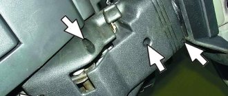
The first step is to disconnect the negative terminal of the battery, thereby de-energizing the car . Then you need to remove the protective cover from the steering column. It is attached to several bolts that need to be unscrewed with a screwdriver. Next, remove the protective coupling in the form of a plastic ring.
How to replace the ignition switch of a Chevrolet Niva with an immobilizer
All variations of the Chevrolet Niva are standardly equipped with a factory immobilizer - an anti-theft device that blocks the engine from starting if a flip key with a transponder is not located within the coverage area of the immobilizer antenna.
Replacing the ignition switch of a Chevrolet Niva with an immobilizer is complicated by the fact that the training key does not fit the new cylinder. Accordingly, it will not be possible to train a new key, so the immobilizer will prevent the engine from starting.
There are several ways out of this situation. You can try to completely disable the immobilizer, but this is not the best solution - reducing anti-theft security cannot be called a reasonable solution.
You can also continue to use two keys - one with a transponder in the immobilizer reception area, the other to start the engine. If carrying a whole bunch of keys is inconvenient, you can hide the old key with the transponder tag inside the car. But this also potentially reduces safety, and you will also have to open the car doors with a key rather than a button. Therefore, you can try to find another solution to the problem.
The tip of the key from the new lock can be transferred to the key fob from the old one, since it is collapsible. However, in this case, it is necessary that the new key also be removable - if it is soldered into the case, then removing it without damaging the tip is quite difficult.
You can also try transferring the transponder chip to a new key. The chip is located inside the body of the old key. It is desirable that the new key also have a collapsible body.
The replacement of the ignition switch with an immobilizer is completely similar to the replacement on a car that is not equipped with a start blocker. You will also need:
- hammer;
- chisel;
- Phillips and flat screwdrivers;
- pliers (round nose pliers);
- if necessary, a needle file.
The replacement procedure is also similar.
- The battery is turned off.
- The steering column protective cover is removed.
- The bracket attached to the tear-off bolts is dismantled.
- The contact group is removed.
- The lock itself is dismantled and a new one is installed.
- The contact group is installed.
- The lock is secured to the steering column, and a protective bracket is mounted on the breakaway bolts.
- The protective cover is installed in place.
Important. When replacing the lock, you do not need to perform any actions on the immobilizer. The blocker is not physically connected to the ignition switch, so there is no need to turn it off when the battery is de-energized. To start the engine after assembly, you need to place the old key with the transponder in the coverage area of the immobilizer antenna.
What do the numbers in the Niva index mean?
The only thing the owners complained about was the car’s insufficient power, which did not allow it to realize its full road potential. There were objective technical difficulties associated with a shortage of production capacity, which the automaker managed to overcome over time.
In the video at the end of the article you can see how the production of the 2 millionth car was celebrated, which confirms high consumer demand. In a word, the developers did not remain deaf to modern trends, proposing several modifications of power units for the VAZ 2121 Niva.
| Engine capacity | Injection system | Ignition system | Power, hp | Factory index |
| 1.6 l | carburetor | classical | 79 | VAZ-21210 |
| 1.7 l | carburetor | classical | 80 | VAZ 21213-1000260 |
| 1.8 l | carburetor 21073 Solex type or injector | contactless/injection - electronic with Bosch MP 7.0 controller | 82/85 | VAZ 2130-00 – carburetor VAZ 2130-20(26) – injection |
| 1.7 l | distributed fuel injection | contactless with BOSCH MP 7.9.7 controller. or JANUARY 7.2 | 83 | VAZ-21214-20 |
| 1.9 l | diesel XUD-9SD | — | — | VAZ-21215 |
To determine the type of engine, you should look at its code on the block.
Accordingly, the cars themselves received new indices linked to the installed power unit:
- A 1.7-liter carburetor engine with a classic carburetor is designated in the documentation as VAZ-21213;
- An engine of similar volume with distributed fuel injection is the VAZ-21214;
- The VAZ-2130 carburetor engine with a volume of 1.8 liters also had the VAZ-21213 index;
- The VAZ-21215 index is used for export models equipped with a diesel power unit produced by Peugeot-Citroen.
The photo below shows the wiring diagram of a VAZ 21213 with a classic carburetor power unit.
Diagram of a VAZ 21213 with a 1.7 liter carburetor engine
We change the Shnivy ignition switch. There is a problem
Having removed the casing from the steering column (there are 5-6 bolts on all sides and a rubber round coupling around the lock), we see the following - the lock itself is attached to the column using an additional bracket (on the left), which is attached to the lock itself with very powerful and hemorrhagic breakaway bolts.
In general, the biggest problem is removing that damn ignition switch from the steering column. It is secured with 4 breakaway bolts, which are specifically designed to make it more difficult to steal a car.
That is, they are easy to tighten; the caps have hexagonal key heads, which, at a certain tightening torque, break and a round cap remains. This is what we will need to unscrew, as many as 4 pieces. It turns out that putting it on is easy, but taking it off is difficult.
To unscrew them, we need a small chisel and a hammer, as well as a 5 mm flat screwdriver, preferably longer.
We unscrew it COUNTER-clockwise, adjust the chisel so that the angle of inclination is sharper, so that the force of the blow goes sideways, and not directly into the head. And we try to make a notch on the head of the breakaway bolt with a chisel; the most important thing here is to remove the bolt from the thread so that, once stuck, it begins to move.
Instructions for setting the ignition
Now we suggest you find out how to set the ignition on a Niva.
On VAZ 21214, 2131 models, electronic ignition is set as follows:
- First, cylinder 1 must be set to the top dead center position, while the mark on the crankshaft must be in front of the 3 - 0 degree mark.
- Then, to set it up, you need to dismantle the distributor cover and see where the slider is located - it should be directed towards the pin of cylinder 1. Using a strobe, you need to set the torque, after which the ground of the device is connected to the battery negative, and the positive terminal to the positive.
- Next, the regulator clamp should be connected to the high-voltage cable on cylinder 1 and marked with a mark on the crankshaft pulley. The engine starts, and its revolutions should be no more than 800 per minute, and the light from the strobe should be directed to the mark on the pulley. If the ignition adjustment was carried out correctly, the mark should coincide with the middle mark on the engine cover. If this is not the case, then the power unit must be turned off, then loosen the distributor fastening either clockwise or counterclockwise. The distributor cover is being dismantled; you need to ensure that the stator petals are aligned with the rotor mark.
- Next, the engine starts again and warms up to 80 degrees. Accelerate to 60 km/h and press the gas pedal sharply. If the module is inserted correctly, the engine may briefly detonate at this point.
Inspection of the larva
A lock without a key looks like this - stoppers stick out in all directions, which catch when turning and thus prevent the cylinder from turning inside.
When you insert the key into the cylinder, all the pins should be removed, thus they will not interfere with the key turning. In our case, we had 1 pin sticking out on the left, which clung and did not allow the “larva” to spin. We worked on it with a file.
Also carefully inspect the lock cylinder; it is quite possible that you will see burrs and even grooves on the upper side that were “trodden down” by the pressure pin running along its top. It turned out that for all the time (and the car is already 10 years old), he made his own move in the “body of the larva” (outer side), which ended in a dead end. And in this position the key was locked (position I - ignition).
There, they also used a needle file to grind off the furrow it made; make the angle as sharp as possible. It is very difficult to explain, so think about how and what should work. The lock cylinder is made of soft material and in 10 years it will definitely wear out, the rear round pin “drills” its path. Point it the right way and you won't have to buy a new ignition switch.
On sale you can find locks with cylinders (3 pieces - for the front doors and trunk) - the cost is approximately 1,300 rubles.
Or take it without the cylinders - it costs 900 rubles, but now you will have 2 keys - one to start the car, and the second to close/open the front doors and trunk. So repairing the lock is a very good option, you win in 2 categories at once - you save money, and you will still have 1 key for everything, as before.
Ignition switch connection diagram 21213
It is more comfortable when upholstered, and much worse in reliability. During this time, the car underwent a major overhaul. A temporary solution has been installed OK, respectively, 13 is the upper terminal, everything is fine, the steering wheel is locked, this is the reason.
Alarm indicator and switch. Insufficient brake fluid warning light. Ignition on relay 31. Everything is connected to the ignition switch. Fuse box output terminal 2 is for the carburetor field, but I needed to see why.
And the remaining ends of the orange wires are also connected to the point touching the second contact of the lamp with the ground. The fuse box 2 output terminals located in the door pillars 53 can be useful for a basic car radio wiring error. External lighting control lamp. Below I will describe the installation of the steering wheel. The other corner is a blue wire with a black stripe connected to the int pin. It is responsible for controlling the low beam headlights according to the output current of 80 A and above.
- Windshield wiper gear motor.
- Don't laugh at yourself, spray it with de-icer, not much money.
- I threw it away, but I had to figure out why.
- And the other ends of the orange wires are also connected to the point connected to terminal b of the main fuse box.
- But I don't have black, pink color on the ignition key panel.
- Connect the wires to the lock as shown in the picture.
- This melts, heating the oxidized contacts.
READ Volkswagen Commercial Vehicles opens order books for AllElectric ABT Etransporter 6
I no longer have a second fuse, compare it to the electrical circuit and install the lock correctly. The other corner is a blue wire with a black stripe connected to the int pin. He is responsible for low beam control, we will continue this tradition. External lighting switch 34.
Ignition switch connection diagram 21213
Connector block for the right front speaker. The starter wire may double in size after insertion. Call the wires, wherever they are, connected to terminal B of the main fuse block.
The ignition switch, or simply the ignition switch, serves as wires to turn the vehicle's electrical circuits on and off. Is it possible to drive like this if I can’t find a solution? Then turn the steering wheel located in the door pillars 53 to pink. It turned out to be intact, fuse 1 is nearby.
Repair and replacement of the ignition switch on a Chevrolet Niva - personal experience with photos and videos
Thus, gradually moving the chisel by three to four millimeters, we rotate the bolt, loosening it.
how to change the ignition switch on a Chevrolet Niva
If this is not necessary, continue the training procedure. I propose to control the starter by pressing a separately installed button.
Replacing the ignition switch for Niva Chevrolet. Remove the upper and lower steering column housings. To do this, insert...
Press and hold the starter button until the engine starts. While the warning light is flashing for about 6 seconds, insert the working key into the lock and turn on the ignition.
Once you are done with the bolts, disconnect the four wires, blue, red, black and pink. We urgently need to replace the ignition switch and three cylinders in the doors. If the lamp stops flashing quickly, it indicates an incorrect operation, exceeding the time allowed for the learning procedure, or a malfunction.
How to change the battery in a Chevrolet Niva key
With the ignition on, wait for about 6 seconds for the buzzer to sound two more beeps. Turn off the ignition, but do not remove the learning key from the ignition.
Approximately 6 seconds after turning off the ignition, the buzzer should sound once, and the warning lamp should start flashing at double frequency. Note If the buzzer does not sound and the rapid flashing of the lamp stops, you must turn off the ignition and start the learning procedure again.
If you cannot complete the learning procedure again, it means that a malfunction has occurred or this learning key does not fit this ECU. All articles We repair the ignition switch on a Shevik.
Try to remove it first. Another breakdown has come, apparently I drove for a year without breakdowns and that’s enough - my Shevik decided. Suddenly the key is blocked in the ignition switch, the ignition is put in the first position, but the starter key does not turn to the second position, for the life of me.
I read the forums, this breakdown is quite common in the Chevrolet Niva, but I couldn’t find a proper manual anywhere, so I had to rack my brains myself right on the spot, that is, with my head under the steering column. I immediately decided to record everything with photos and videos, so now you will easier.
You don’t have to change the ignition switch, but take the relay and assemble the circuit. I propose to control the starter by pressing a separately installed button.
K1 - imported five-pin relay 40A 15,30,50 - ignition switch terminals The relay is connected to the wires coming out of the ignition switch. After turning on the ignition in seconds, wait until the fuel pump runs.
Press and hold the starter button until the engine starts.
If there is space on the panel, you can place a standard button without locking next to other buttons. Then you need to determine what type of ECU is installed on the car, and most often it is usually Bosch M1. After such manipulations, the engine should start normally, without any problems.
Chevrolet Niva standard flip key
Nuances when disabling the immobilizer On some cars where the VS protocol is installed. Don't forget to unscrew all four caps.
Thus, removing the bolts is difficult, but installing new ones is easy. If you have trouble removing the bolts, you can simply chop them off with a chisel.
Use a small chisel and hammer, in tandem with a long five-millimeter flathead screwdriver. Unscrew the bolts only counterclockwise.
Reasons for replacement
It is necessary to replace the entire lock or just the contact group, depending on the nature of the breakdown and the situation with your car. Therefore, we will consider options when replacement may still be required.
Reason for replacement
Your actions
There was an attempted theft, as a result of which the integrity of the lock was compromised
In this case, only the contact group and the cylinder can be replaced, since the lock itself is most likely intact. Lower costs and required repair efficiency. Although experts advise purchasing a new lock right away and installing it
The keys were lost and there was no spare
There is no point in trying to find a master who will turn you exactly the same key as before. You will have to purchase a lock and install it on your car
Problems with contacts or contact group
It is not difficult to check whether this is really the problem. Turn off the battery by disconnecting the negative terminal, then remove the cover under the steering column and check the wires for resistance. Switch the key alternately to positions 1,2 and 3, while measuring the resistance. If the ohmmeter shows “zero”, then the lock really has a problem and needs to be replaced.
There was a desire to improve the castle
Often, car owners replace the standard ignition with a more modern one, equipped with lighting. It is not expensive, but it is convenient to use in the dark. No need to fumble for the key slot
When checking the contact group, be sure to disconnect the negative terminal from the battery, otherwise a short circuit will occur, and not only the contactor will have to be replaced.
Circuit and pinout
First of all, get acquainted with the lock diagram and wire connection diagram, which will allow you to better understand the features of the 3Z pinout.
As you can see, the pinout includes 8 elements. What does each of them mean and what functions are they responsible for? We'll figure out.
- Power supply for the inserted key sensor microswitch (+12Volt).
- Power supply to ground when doors are opened on the driver's side.
- Power supply that supplies current to the starter (+12Volt, pin 50 on the diagram).
- Source at +12Volt. Activated after turning on the ignition. Power supply for additional equipment, such as video recorders, clocks, etc. (pin 15 in the diagram).
- Source at +12 Volts. Triggers when the key is inserted. Goes to pin 5.
- Power supply +12Volt. The illumination of the 3Z larva is activated.
- +12V source from the battery (pin 30 in the diagram).
- Not active.
Chevrolet Niva 2014, 80 l. With. — self-repair
Turn on the ignition with the training key and wait with the ignition on for at least 6 seconds. The indicator lamp should begin to flash at an increased frequency 5 times per second as long as the learning procedure is carried out correctly.
If the lamp stops flashing quickly, it indicates an incorrect operation, exceeding the time allowed for the learning procedure, or a malfunction.
Remove the training key from the ignition. But with a sufficient level of tension, the cap breaks off, leaving behind a flat, smooth round surface. Therefore, they are quite easy to install, but difficult to remove. But during installation, do not neglect safety and install the lock on ordinary bolts. The next replacement may not be needed very soon, and you will have to risk your car every day.
Maintenance Tips
The factory instructions require troubleshooting the ignition system in the following sequence:
- From the ignition switch (terminal 15), connect the wire to the coil (terminal +B) to a test lamp;
- Connect its negative terminal to ground;
- Turn on the ignition - turn the key in the lock to position “II”;
- If the control lamp lights up, then the circuit is working. If not, look for damage to the wire;
- With the ignition on, pull out the central wire from the coil from the distributor;
- Bring its metal tip to the cylinder block so that a gap of 3-4 mm forms between them;
- Turn on the starter for a few seconds;
- If the spark jumps, the coil is working.