The ignition system of the VAZ 2106 car in the figure is represented by a distributor (3), a reel (6), spark plug elements (5), an ignition switch (2), wires with high voltage insulation, which are distributed to spark plug elements and a coil from the distributor and low-voltage connecting wiring .
In addition to the contact ignition system of the VAZ 2106, the “sixes” also use an ignition circuit using transistors that switch the current pulse and supply it to the spark plugs.
These include:
- Breaker-distributor. Initially, the first models until the 80s of the twentieth century were equipped with the R-125B device. It was equipped with a mechanical octane corrector, which adjusted the angular value of the ignition timing in a small range, but it was not equipped with a vacuum type regulator. After this, the ignition and fuel supply systems were modernized, as a result of which a distributor with a regulator of the vacuum operating principle and a compatible “Ozone” carburetor appeared.
- Bobbin B117-A is a contour type, with a disconnecting magnetic circuit, filled with special oil, sealed.
- Spark plugs A17DV or their export analogues.
- Ignition switch VK347 with an anti-theft gadget, operating on the following principle: after the ignition key is moved to position III “Parking”, a metal lock pops out of the body part, which falls into a special groove in the steering shaft and does not allow it to rotate.
For emergency repairs of the ignition system of a VAZ 2106 car, it is necessary to have in stock the parts that most often fail. This is a reel and a distributor capacitor; they do not take up much space. Unfortunately, they cannot be repaired.
Malfunctions of the “six” ignition system
When operating a vehicle, the following malfunctions of the ignition system occur, which must be eliminated before further driving the vehicle.
| Malfunction | Remedy |
| The contact group has a coating of dirt, is oxidized or there are contact burn points, the distance between the contacts is increased | It is necessary to clean the contact group and adjust the gap |
| Weak fasteners or wiring caps in the low-voltage circuit have oxidized, a broken wire or a short circuit to the car body | Test the wiring and their connections, replace damaged sections of the circuit |
| Defective ignition switch (no contact closure) | Test the area, replace the defective contact element of the ignition switch |
| The capacitor is broken and does not hold capacity | Replace the product |
| There is no voltage in the primary type bobbin winding | Replace the product |
| Incorrect adjustment size in the distributor contact group | Set recommended size in contact group |
| Excessive wear of the PCB pad or increased diameter of the distributor lever bushing | Replace contact group |
| Defect in the bearing of the movable type distributor plate | Replace the bearing or the entire distributor |
| The ignition spark plug elements have an uncertain contact in the threaded part of the cylinder head, the spark plug caps from the insulated HV wires have broken or become oxidized; the insulated HV wires are dirty or their insulating layer is damaged | Test the contacts and, if necessary, restore the joints, clean or change the wiring |
| The corner of the distributor cover has undergone severe wear or has become defective and is in a non-contact state | Check the carbon of the distributor cap and, if necessary, replace it |
| Loss or loss of voltage through chips, through cracks or burnout points in the cover or rotor part of the distributor, as well as through a layer of soot or drops of moisture on the internal cavity of the distributor cover | Carry out a check, clean the cover from foreign layers of moisture and soot, replace the distributor elements (cover and rotor) if they are damaged |
| Failure of the resistance in the slider (distributor rotor) | Replace the slider resistance |
| The car bobbin has external or internal defects | Replace the car bobbin |
| The glow elements of the spark plugs (electrodes) are dirty with oil or the gap between the interacting elements is set incorrectly | Clean the spark plug elements and carry out adjustments to align the gap between the interacting elements |
| Ignition spark plug elements have external defects in the form of cracks and chips on the insulator element | It is necessary to replace spark plug elements with updated products |
| Incorrect connection of high-voltage wires to the contacts on the car distributor cover | Connect the high voltage wires according to the appropriate diagram (1-3-4-2) |
| Incorrect installation of the ignition in the vehicle | Test the installation of the MH and, if necessary, adjust it |
The table below will help you diagnose and troubleshoot problems that may arise.
The car is equipped with an engine start lock, typical for the entire line of VAZ cars, consisting of three main parts: a contact part, an anti-theft device and the lock itself.
When the anti-theft device of the lock is released, the device is replaced as a complete set. The contact part, secured in the ignition housing with a snap ring, can be replaced separately. The vehicle starting device is installed under the instrument panel on the driver's left side on the steering shaft bracket.
The flawless operation of any car depends on the trouble-free and coordinated operation of all its mechanisms. Not the last place in this series is the correct installation of the ignition system. After the car leaves the assembly line, the correct clearance is set by factory specialists. During long-term use of the car, a malfunction may occur, which may lead, as one of the reasons, to excessive fuel consumption, or as one of the main reasons, the car will stop starting. In this case, it will be necessary to install the VAZ 2106 ignition according to the factory technical parameters. You can do this yourself, having done all the necessary work yourself, or contact a professional who is familiar with all the nuances of correctly installing the ignition system.
Device malfunctions
Replacement and repair of the distributor on the domestic “six” is carried out in the event of incorrect operation of the mechanism.
We recommend: How to clean the air conditioner on a Kia Rio 3?
Below are the main symptoms of breakdowns that indicate possible malfunctions:
- The vehicle jerks while driving. Moreover, these jerks are completely uncharacteristic of a car.
- The engine generally does not start.
- When trying to accelerate the car, the car may also jerk, and the acceleration process itself takes a lot of time, and the engine may detonate - the piston rings knock.
- Increased fuel consumption.
As you can see, in general the symptoms are similar to those that appear when the ignition is set incorrectly. Of course, if such symptoms appear, it cannot be said for sure that the fault lies in the distributor, but attention should also be paid to diagnosing this unit.
As for the breakdowns that may force the car owner to repair or replace the mechanism, they are as follows:
- The unit slider is worn out and burnt out.
- The problem lies in the cover itself - the contacts on it could have burned out.
- Hall sensor failure. The problem may be associated not only with a breakdown of the controller, but also with poor contact on the regulator plug.
- Another reason that domestic drivers encounter quite often is the distributor bearing. After a long period of use, it could become loose, but it could also simply jam.
- Presence of mechanical damage, including cracks on the cover.
- Engine fluid gets into the distribution unit; usually the problem is related to the seal of the cap.
Electronic ignition VAZ 2106
Ignition system. 1. Insulator; 2. Ignition coil housing; 3. Insulating paper windings; 4. Primary winding; 5. Secondary winding; 6. Primary winding insulating tube; 7. Output terminal for the end of the primary winding; 8. Contact screw; 9. High voltage terminal; 10. Cover; 11. Terminal “+E” for the output of the beginning of the primary and end of the secondary windings; 12. Central terminal spring; 13. Secondary winding frame; 14. External insulation of the primary winding; 15. Fastening bracket; 16. External magnetic circuit; 17. Core; 18. Contact nut; 19. Spark plug insulator; 20. Rod; 21. Spark plug body; 22. O-ring; 23. Heat sink washer; 24. Central electrode; 25. Side electrode of the spark plug; 26. Distributor roller; 27. Roller oil deflector clutch; 28. Washer; 29. Wire for power supply and distributor; 30. Cover locking spring; 31. Vacuum regulator housing; 32. Diaphragm; 33. Vacuum regulator cover; 34. Nut; 35. Vacuum regulator spring; 36. Vacuum regulator rod; 37. Cam lubrication wick; 38. Ignition timing regulator support plate; 39. Distributor rotor; 40. Side electrode with terminal; 41. Distributor cover; 42. Central electrode with terminal; 43. Angle of the central electrode; 44. Central rotor contact; 45. 5-6 kohm resistor to suppress radio interference; 46. External rotor contact; 47. Ignition timing regulator spring; 48. Centrifugal regulator plate; 49. Weight of ignition timing regulator; 50. Insulating sleeve; 51. Breaker cam; 52. Lever insulating block; 53. Breaker lever; 54. Stand with breaker contacts; 55. Breaker contacts; 56. Movable breaker plate; 57. Capacitor 0.20-0.25 µF; 58. Engine start distributor housing; 59. Bearing of the movable plate of the breaker; 60. Oiler body; 61. Terminal clamp screw; 62. Bearing lock plate; 63. Distributor; 64. Candles; 65. Ignition switch; 66. Ignition coil; 67. Generator; 68. Battery; 69. Sensor-distributor; 70. Switch; 71. Ignition timing; 72. To power supplies; 73. I. Ignition coil; 74. II.Spark plug; 75. III. Ignition distributor; 76. IV. Scheme of the classical system; 77. V. Scheme of operation of the centrifugal ignition timing regulator; 78. VI. Diagram of a contactless system.
The principle of operation of the ignition coil
Rice. Sectional view of the ignition coil: 1 - insulator; 2 - housing, 3 - insulating paper, 4 - primary winding, 5 - secondary winding, 6 - primary winding output terminal (designations: “1”, “-“, “K”), 7 - contact screw, 8 - central terminal high voltage, 9 - cover, 10 - power terminal (designations: “+B”, “B” “+”, “15”), 11 - contact spring, 12 - bracket, 13 - outer wire, 14 - core.
The figure shows a cross-section of the ignition coil and one of the winding connection diagrams. Let us repeat what was stated earlier: the coil
is a transformer with two windings wound on a special core.
First, the secondary winding is wound with a thin wire and a large number of turns, and on top of it the primary winding is wound with a thick wire and a small number of turns. When the contacts are closed (or in another way), the primary current gradually increases and reaches a maximum value determined by the battery voltage and the ohmic resistance of the primary winding. The increasing current of the primary winding meets the resistance of the emf. self-induction directed counter to the battery voltage.
When the contacts are closed, current flows through the primary winding and creates a magnetic field in it, which crosses the secondary winding and a high voltage current is induced in it. At the moment the breaker contacts open, an emf is induced in both the primary and secondary windings. self-induction. According to the law of induction, the greater the secondary voltage, the faster the magnetic flux created by the magnetic current of the primary winding disappears, the greater the ratio of the number of turns, and the greater the primary current at the moment of break.
This design is typical when building ignition systems using breaker contacts. The ferromagnetic core can be saturated with the primary current, which would lead to a decrease in the energy accumulated in the magnetic field. To reduce saturation, an open magnetic circuit is used. This allows you to create ignition coils with a primary winding inductance of up to 10 mH and a primary current of 3-4 A. Higher current cannot be used because At this current, the contacts of the breaker may begin to burn.
If the inductance in the coil is Lk = 10 mH and the current I = 4 A, then the energy W in the coil can be stored no more than 40 mJ with efficiency = 50% (W = Lk * I * I/2). At a certain value of the secondary voltage, an electric discharge occurs between the electrodes of the spark plug. Due to the increase in current in the secondary circuit, the secondary voltage drops sharply to the so-called arc voltage, which maintains the arc discharge. The arc voltage remains almost constant until the energy reserve becomes less than a certain minimum value. The average duration of battery ignition is 1.4 ms. This is usually enough to ignite the air-fuel mixture. After this, the arc disappears; and the residual energy is spent on maintaining damped voltage and current oscillations. The duration of the arc discharge depends on the amount of stored energy, mixture composition, crankshaft rotation speed, compression ratio, etc. As the crankshaft rotation speed increases, the time of the closed state of the breaker contacts decreases and the primary current does not have time to increase to the maximum value. Because of this, the amount of energy accumulated in the magnetic system of the ignition coil decreases and the secondary voltage decreases.
The negative properties of ignition systems with mechanical contacts appear at very low and high crankshaft speeds. At low rotation speeds, an arc discharge occurs between the breaker contacts, absorbing part of the energy, and at high rotation speeds, the secondary voltage decreases due to the “bouncing” of the breaker contacts. Contact systems have not been used abroad for a long time. Cars produced in the 80s are still driving along our roads.
Some ignition coils work with an additional resistor. A functional diagram of connecting such a coil to a contact ignition system is shown nearby.
Rice. Connection diagram of the ignition coil with the contact ignition system: 1 - spark plugs, 2 - distributor, 3 - starter, 4 - ignition switch, 5 - starter solenoid relay, 6 - additional resistance, 7 - ignition coil.
The connection diagram of the coil windings is different. During starting modes, when the voltage on the battery drops, the additional resistor is short-circuited by the auxiliary contacts of the starter solenoid relay or the contacts of the additional starter activation relay, which provides the primary winding of the ignition coil with an operating voltage of 7-8 V. At engine operating modes, the supply voltage is 12-14 V. The additional resistor is usually wound from constantan or nickel wire. If the wire is nickel, then such resistance is called a variator due to the change in resistance depending on the amount of current flowing through it: the greater the current, the higher the heating temperature and the higher the resistance. At increased crankshaft speeds, the strength of the primary current drops, the heating of the variator weakens and its resistance decreases. Tzh. Since the secondary voltage depends on the rupture current in the primary circuit, the use of a variator makes it possible to reduce the secondary voltage at low speeds and increase them at high engine speeds.
In transistorized ignition systems, the primary current is interrupted by a power transistor. In such systems, the primary current is increased to 10 - 11 A. Ignition coils with low primary winding resistance and high transformation ratio are used. We present samples of oscillograms taken in a working system on the primary and secondary windings of the ignition coil.
Rice. Oscillogram of the primary winding.
Rice. Oscillogram of the secondary winding.
The shape of the oscillograms is very similar, because The coil windings are interconnected by a transformer connection (mutual induction). The coils of contact-transistor and transistor ignition systems have a classic design: oil-filled, with an open magnetic circuit, in a metal case. Let's give some data on produced domestic ignition coils.
As shown in the table, ignition coils differ in the number of turns in the windings and the transformation ratio in various ignition systems. The coil designs differed little.
Ignition installation for VAZ-2106
Before installing the ignition system, it is necessary to check the gap of the breaker contacts, which should be within 0.35 ± 0.05 mm. If the gap does not correspond to these parameters, then it will be necessary to install it using a twelve-sided wrench measuring 39 mm. A control lamp helps to set the ignition correctly on the VAZ 2106.
If there is no test lamp available, then you can install it on a spark by connecting a spare spark plug, which will help prevent system failure during work. The ignition is considered to be correctly set when the spark in cylinder I or IV jumps between the first and second exhaust marks. It is worth adding that in the event of oxidation of the breaker contacts, the control lamp will light constantly, regardless of the position of the distributor body.
The most common cases of malfunction of the VAZ 2106 electronic engine start include: failure of the 900706U ball bearing in the distributors, especially the latest years of production, which are equipped with a vacuum corrector diaphragm, breakdown of the distributor cap, slider and resistor in the slider.
The destruction of the ball bearing leads to uneven operation of the car engine at idle and it stops working at full power, while the tachometer needle can “walk” across its entire scale, regardless of engine speed. This situation can be corrected by performing a few simple steps:
- disconnect the vacuum hose from the distributor;
- Having tied a strong knot at its end, put it away so that it does not dangle;
- use a bar to press the vacuum corrector rod in accordance with Figure 24a; if the bar does not fit between the bend of the rod and the body, then its end is made slightly narrower, as shown in Figure 27b;
- re-adjust the gap in the breaker contacts, as described above;
- set the ignition angle to +7°30'
Now you can drive as with the ignition distributor of the first editions, but it is worth considering that in this case there will be an increase in fuel consumption by approximately a third and an increase in exhaust toxicity.
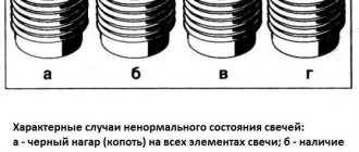
In many ways, the correct operation of the engine starting system depends on the spark plugs installed on it. With just a visual inspection of the spark plugs, you can determine the malfunction of the piston group, ignition and power systems. A spark plug with an oily working surface cannot be restored.
You can try to restore the spark plug by installing it on the second or third cylinders of a well-heated engine, or sandblast the working part. It is recommended to replace spark plugs after every 30,000 km. mileage
02/23/2013Found a mistake? Select the text with the mouse and press Ctrl+Enter Was this information helpful?
The VAZ-2106 car was produced from 1976 to 2008. This guide provides color-coded wiring diagrams (for the injector and carburetor) with a description of all elements for various modifications. The information is intended for self-repair of the six. Electrical circuits are divided into several blocks for ease of viewing via a computer or phone; there are also circuits in the form of a single picture with a description of each element - for printing on a printer. All electrical equipment of a car can be divided into the following components:
- engine starting system;
- battery charge elements;
- fuel mixture ignition system;
- elements of external and interior lighting;
- sensor system on the instrument panel;
- sound notification elements;
- fuse block.
Installation of BSZ on VAZ 2106
When choosing a contactless ignition kit, pay attention to the engine size of your “six”. The distributor shaft for a 1.3 liter engine should be 7 mm shorter than for more powerful 1.5 and 1.6 liter power units.
To install BSZ on a VAZ 2106 car, you should prepare the following set of tools:
- open-end or spanner wrenches with sizes 7-13 mm;
- flathead and Phillips head screwdrivers;
- pliers;
- drill with a 4 mm drill (to mount the electronic unit in the side member you will have to make 2 holes for self-tapping screws).
I highly recommend purchasing a 38 mm socket wrench with a long handle for unscrewing the ratchet. It is inexpensive, around 150 rubles, and is useful in many situations. Using this key, it is easy to turn the crankshaft and set pulley marks to adjust the ignition and timing.
The first step is to dismantle the old system - the main distributor and coil:
- Pull out the high-voltage wires from the sockets of the distributor cover and disconnect it from the body by unlocking the latches.
- When turning the crankshaft, set the slider at an angle of approximately 90° to the engine and place a mark on the valve cover opposite. Unscrew the 13 mm nut securing the distributor to the block.
- Unscrew the clamps of the old coil and disconnect the wires. It is advisable to remember the pinout or sketch it.
- Loosen and unscrew the nuts securing the clamp, remove the coil and distributor from the car.
When removing the ignition distributor, keep the washer-shaped gasket installed between the part platform and the cylinder block. It may be useful for a contactless distributor.
Before installing the BSZ, it is worth checking the condition of the high voltage cables and spark plugs. If you doubt the performance of these parts, it is better to change them immediately. Serviceable spark plugs must be cleaned and the gap set to 0.8-0.9 mm.
Install the contactless kit according to the instructions:
- Remove the BSZ distributor cap and, if necessary, replace the sealing washer from the old spare part. Turn the slider to the desired position and insert the distributor shaft into the socket, lightly pressing the pad with a nut.
- Replace the cover, securing the latches. Connect the spark plug cables according to the numbering (the numbers are indicated on the cover).
- Screw the coil of the contactless system to the body of the VAZ 2106. To ensure that terminals “B” and “K” are in their original position, first unfold the body of the product inside the mounting clamp.
- Place the wires from the ignition switch and tachometer onto the contacts according to the diagram above.
- Install the controller next to the spar by drilling 2 holes. For convenience, remove the expansion tank.
- Connect the wiring harness to the distributor, switch and transformer. The blue wire is connected to terminal “B” of the coil, the brown wire is connected to terminal “K”. Place a high-voltage cable between the distributor cover and the central electrode of the transformer.
If there were no annoying mistakes during the installation process, the car will start immediately. The ignition can be adjusted “by ear” by loosening the distributor nut and slowly turning the housing at idle engine speed. Achieve the most stable operation of the motor and tighten the nut. Installation is complete.
Video: instructions for installing contactless equipment
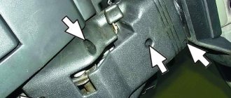
VAZ2107 fuse and relay diagram
The electrical wiring of the machine is protected by fuses, which are mainly installed in the central and additional units, located at the bottom of the instrument panel on the left side next to the steering column. The circuit from the battery to the terminals and connections is closed when the car ignition is turned on.
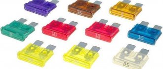
Owners of 2106 should be aware that the old design of fuses has long become obsolete, since each time they operate they overheat, which affects the density of the cells. Lack of tight contact between the fuse and the connectors leads to their burning. Therefore, replacement of the fuse blocks is necessary. To avoid unnecessary problems with the electrical wiring, you should inspect the safety devices every six months. If the contact part burns, it is necessary to replace the fuses and clean the sockets. Today, many VAZ 2106 owners are modernizing classic blocks, replacing them with modern blade fuses.
Modifications of the VAZ-2106 car
VAZ-21060 . Modification with the symbol VAZ-21060, Izhevsk assembly of recent years of production with a VAZ-21067 injection engine with a catalyst that meets the Euro-2 environmental standard
VAZ-21061 . Modification with a VAZ-2103 engine, some cars with a similar index were equipped with a simplified engine cooling system and did not have an electric fan. Instead, an impeller was installed on the end of the coolant pump shaft. Already Russian cars were equipped with bumpers from the VAZ-2105, some examples were equipped with cleaners and headlight washers.
VAZ-21062 . Export, right-handed modification of the base six.
VAZ-21063 . A car with an improved VAZ-21011 engine, with an oil pressure sensor and an electric engine cooling fan. The release of this modification was completed in 1994.
VAZ-21064 . Export, right-handed modification, like the VAZ-21062, but the VAZ-21061 modification was taken as the basis
VAZ-21065 . A modification of the car with improved equipment, which was produced from 1990 to 2001. An engine with a volume of 1569 cm3 was installed as a power unit. Other differences from the base model include a more powerful generator, a 5-speed gearbox, a rear axle gearbox with a gear ratio of 3.9, a contactless ignition system, and a Solex carburetor. There were other changes both in the exterior and in the interior, in general it was a “luxury” version of the VAZ-2106 sedan.
VAZ-21065-01. The same VAZ-21065 but with a VAZ-2103 engine
VAZ-21066 . Export, right-hand drive modification of the VAZ-21063 car.
VAZ-21068 . A car that was produced as a carrier of units during the development period of the new VAZ-2108 and VAZ-21083 engines.
VAZ-21069 . Modification of the VAZ-2106 manufactured by order of the special services. It was equipped with a two-section rotary piston engine VAZ-411 with a power of 120 hp, VAZ-413 with a power of 140 hp.
Contact ignition system VAZ 2107
The classic contact system used on the VAZ consists of 6 components:
- Ignition switch.
- Breaker-distributor.
- Spark plug.
- Low voltage wires.
- Ignition coil.
- High voltage wires.
The ignition switch combines two parts: a lock with an anti-theft device and a contact part. The switch is secured with two screws to the left of the steering column.
The ignition coil is a step-up transformer that converts low voltage current into the high voltage needed to produce a spark in the spark plugs. The primary and secondary windings of the coil are placed in a housing and filled with transformer oil, which ensures their cooling during operation.
The ignition distributor is the most complex element of the system, consisting of many parts. The function of the distributor is to convert constant low voltage into high pulsed voltage with the distribution of pulses across the spark plugs. The design of the distributor includes a chopper, centrifugal and vacuum ignition timing regulators, a movable plate, a cover, a housing and other parts.
Contactless ignition system VAZ 2107
The electronic ignition circuit of the VAZ 2107 received the name “contactless” because the circuit is opened/closed not by the breaker contacts, but by an electronic switch that controls the operation of the output semiconductor transistor. The electronic (non-contact) ignition system kits for the VAZ 2107 on carburetor and injection engines are somewhat different, so there is a misconception that electronic and non-contact ignition are different systems. In reality, the operating principle of electronic ignition systems is the same.
Like a contact ignition system, electronic ignition includes spark plugs, wires, an ignition coil and a distributor. The only difference is the presence of a switch that controls the supply of high voltage to the spark plugs.
Electronic spark plugs
When installing BSZ on a VAZ 2106 model car, it is advisable to select and install spark plugs that are optimally suitable for electronic ignition. Along with Russian spare parts, the use of imported analogues from well-known brands is allowed:
- original spark plugs recommended by the manufacturer - A17DVR (M);
- NGK - BCPR6ES-9, BPR6ES-9;
- Bosch - FR7DCU, WR7DC;
- Brisk - DR15YC, LR15YC;
- Beru - 14FR-7DU, 14R-7DU.
The letter M in the marking of domestic parts indicates copper plating of the electrodes. There are A17DVR kits on sale without copper coating, which are quite suitable for BSZ.
The gap between the working electrodes of the spark plug is set within 0.8-0.9 mm using a flat feeler gauge. Exceeding or decreasing the recommended clearance leads to a drop in engine power and an increase in gasoline consumption.
Installing a non-contact spark generation system significantly improves the performance characteristics of carburetor Zhiguli cars equipped with rear-wheel drive. Unreliable, constantly burning contacts caused a lot of trouble to the owners of the “sixes”. At the most inopportune moments, the breaker had to be cleaned, getting your hands dirty. The first electronic ignition appeared on front-wheel drive models of the “eighth” family, and then migrated to the VAZ 2101–2107.