09.07.2020
7614
Repair
Today I will talk about the main reasons why a carburetor engine fails using the example of a VAZ 2106 (2101 - 2103).
To begin with, so as not to get confused later, I will make a small digression. Initially, these cars were produced with a contact ignition system. But progress does not stand still and we all know very well that contact ignition, so to speak, is not the best. Therefore, over time, car enthusiasts began to install a contactless ignition system. Based on this, first I will talk about the contact ignition system, and at the end I will make small amendments for the BSZ.
The first thing I would advise you to do if the VAZ 2106 engine has failed is to determine which cylinder is not working. There is a wonderful old-fashioned way to do this - you need to remove the explosive wires from the spark plugs one by one. (It is better to do this with gloves). If, when the armored wire is removed, the engine operation does not change in any way, then this particular cylinder is inoperative.
Now we need to figure out why it doesn't work. Let's start with the most basic thing - you need to check the high-voltage wire and spark plug.
Switch Purpose
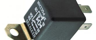
The non-contact ignition system is distinguished by the fact that the electrical impulse supplied to the coil (coils) is generated not by the breaker contact installed in the distributor, but by the switch. The electronic circuit of the latter supplies a spark to the cylinders with an optimal timing, based on data about the current operating mode of the engine and the position of the crankshaft at each specific moment.
The switch is able to withstand physical stress, vibration and temperature changes over a wide range. The absence of contacts in the circuit ensures greater reliability and durability of the unit. Another advantage of this solution is that the VAZ 2107 switch has the ability to be reprogrammed by the user to set the timing advance corresponding to the fuel quality and dynamic requirements for the vehicle.
VAZ 2107 switch parameters
The operating voltage of the switch is 13.5 volts, the permissible voltage range is from 6 to 16 volts. The maximum switching current is 8.5 amperes. The switch provides stable sparking in the engine speed range from 20 to 7000 rpm.
What is contactless and electronic ignition
You should immediately distinguish between the concepts of “electronic” and “contactless” ignition, since these are fundamentally different systems . The electronic ignition has a crankshaft position sensor and is controlled by it via the ECU (electronic engine control unit). For contactless ignition to work, such difficulties are not necessary. How does it work? In a non-contact type ignition distributor, instead of opening contacts, an induction coil is installed, which produces a high voltage current, which is then supplied to the spark plugs. And then, as usual, the fuel in the cylinders ignites.
Operating principle of the ignition system
The VAZ ignition system is used to ensure ignition of the air-fuel mixture to start the engine. If the VAZ ignition does not work correctly, then most likely the car owner will face the problem of poor engine starting. To prevent this, all elements of the safety system must always be in working order.
The VAZ ignition circuit, in particular, the principle of its operation is as follows:
- the first stage is the accumulation of the charge necessary to start the internal combustion engine;
- the second stage is the conversion of this charge into high-voltage voltage;
- charge distribution along the wires;
- spark formation in spark plugs;
- ignition of a flammable mixture (video author - Mikhail Nesterov).
At each of these stages, the precise operation of all components and mechanisms is important. To ensure optimal operation of the VAZ engine and its cylinders, you need to pay attention to system diagnostics from time to time.
At different positions of the regular or flip key in the lock, different processes occur in the on-board network:
- When the conventional ignition switch is positioned at mark I, the ignition switch on the VAZ actually starts working. This position is fixed; the instrument panel, optics and side lighting, as well as other equipment, operate in it.
- In position II, the device supplies voltage to the starter, which is necessary to start the internal combustion engine. This position is not fixed as the driver moves the switch key into it to start. When the motor starts running, the key should return under the action of the spring.
- III - this position is a parking position, in which all equipment does not work, and the steering column is locked with a latch.
Firing order
VAZ ignition switch connection diagram
An equally important nuance is the ignition order. Every car owner should know the ignition procedure so that in the event of a malfunction of the power unit, he can take action to repair or diagnose it. In classic VAZ models, the ignition order is as follows: first, the spark is supplied to the first cylinder, then to the third, fourth and second.
The firing order should be marked on the breaker cover. Number 1 indicates that the wire goes to the spark plug of the first cylinder. If you look at the VAZ ignition module, you will see that there are numbers on its outputs that will help you connect the wires correctly after disconnecting. The ignition order must not be violated.
Replacing the switch on a contactless ignition system
An unscheduled replacement of the switch on the “six” is carried out when it is impossible to operate the device due to a breakdown. Carrying out work of this kind is very simple; only initial knowledge in plumbing and electrical engineering and the availability of the necessary tools (a set of heads with a wrench and a ratchet) and a replaceable device are required.
This replacement of the VAZ 2106 ignition switch occurs in the following order:
- We disconnect the wiring from the “six” switch, which connects it to the breaker - distributor with a plug:
- We unscrew 2 body fasteners of the VAZ 2106 switch at different edges of the gadget; for this it is better to use a set of sockets with a ratchet and a wrench-extension:
- We dismantle the ignition switch to check it, and if necessary, replace it;
- Installation of this gadget follows the reverse principle.
Non-contact ignition system device
The BSZ device for carburetor engines consists of:
- Distributor. This is a device that is responsible for creating a spark at the right moment. It is also called the ignition system distributor.
- High voltage coil. This element in the ignition system receives low voltage from the battery, converts it and supplies high voltage. Therefore, high-voltage wires come from it. The coil consists of two windings. The primary one is made of a large cross-section wire (connected to the electrical part of the car via the ignition switch relay), the secondary one is made of many turns of thin wire (connected with a high-voltage wire to the distributor).
- Switch. This element of the contactless ignition system is responsible for the formation of a spark. In simple words, a switch is a signal amplifier. The switch is only available in the ignition system of internal combustion engines with a carburetor. By the way, SOLEKS is considered the best carburetor. On injection VAZ 2107, as well as on others, a switch is not needed, since its functions are performed by the on-board computer controller.
- High voltage and normal wiring. High voltage wiring must meet heavy insulation requirements.
- Terminals. Serve for connections and must be strong.
Electronic and contactless ignition systems are the same device. It got its name due to the absence of a contact group in the system design. The ignition switch also has a contact group, which is a common cause of engine failure.
Distributor device:
- frame;
- shaft;
- cam;
- moving contact (slider).
Purpose and types of switches
The VAZ 2106 electronic contactless ignition switch is designed to interrupt the current supply in the primary “bobbin” circuit based on pulses from the sensor, which is responsible for distributing the current supply in the ignition system.
Such switches for the VAZ 2106 come from different manufacturers: Remix, HIM-52, or BAT. The switch circuit has the ability to automatically interrupt the current supply through the ignition system bobbin when the power plant is turned off, but the system is turned on.
This electronic device transforms the directive signals of the non-contact type sensor into electrical impulses arriving at the primary winding of the bobbin. If the VAZ switch of the “sixth” model malfunctions, this defect cannot be eliminated without electronic testing equipment.
Connection
First, we connect the switch and distributor with wiring to the chips. Everything is simple there; it will be impossible to mix up the sides of the installation, since both the distributor and the switch have guides that will allow you to connect the chips only in the correct position.
The black wire coming from the switch must be secured to ground. The contact of this wire with the body should be very good, so it won’t hurt to strip the paint from the body at the attachment point.
The red wire coming from the switch is connected to the ignition coil installed on the car, to terminal “K”. From the old coil we disconnect the two wires connected to terminal “B”. If the wiring on the car has not been changed, then these wires are blue and light blue with a black streak.
When connecting a new coil to the terminals, do not rely on the old one. The fact is that in the new coil these terminals have a mirror position compared to the old one. This must be taken into account so as not to be confused.
We install the cover on the distributor and connect all the high voltage wires. Also connected from the carburetor is a pipeline going to the vacuum regulator. At this point we can assume that the contactless ignition on 2101 is completely installed and connected.
If the contactless ignition of the VAZ-2101 is installed correctly, then the car should start without problems and operate stably in all modes.
Checking the ignition coil
For this purpose, it is necessary to remove the central wire from the breaker-distributor, bring it to the motor housing and turn it with the starter, and a running spark should appear. After this, we check the energy supply to a separate spark plug, for which we unscrew the working spark plug, bring its contact to ground and attempt to start the engine. In this case, the spark should come from the wire to ground. If it is absent, the reason will be a malfunction of such a system element as the VAZ 2106 ignition coil, which plays an important role in the operation of the vehicle.
During the inspection, it is necessary to observe safety precautions and work in protective dielectric rubber gloves. The “six” uses both an ignition system using contacts and a system without using distributor contacts with equal success; accordingly, a different VAZ 2106 coil is used, depending on the type of ignition system.
These types of ignition are checked using almost the same parameters. In this case, we test the system with a multimeter. It must be remembered that in the connection circuit of the VAZ 2106 ignition coil, the voltage in sections of the circuit reaches from 24 thousand to 40 thousand volts. With a small current in the system, this is not life-threatening, but an electric shock can be very sensitive.
Important: To be on the safe side, it is advisable to keep an additional ignition coil and distributor capacitor in the car. These elements of the system quite often cause the system to fail, and such products cannot be repaired. If these components are defective, it is not possible to start the engine, but replacing them is not difficult. As a last resort, in the absence of standard products, you can temporarily install analogues from other VAZ models.
Contact angle correction in closed state
Adjusting the ignition of the VAZ 2106 begins with the simplest operation of removing the distributor cover, then turning the crankshaft until the maximum distance between it and the distributor is reached. After this, they begin to unscrew the screws that fix the contact group on the bearing plate and between the contacts, and insert a probe to determine and select the optimal position for the group. Ideally, everything is determined by the force applied to move the probe, which should be minimal; having found an area that meets this requirement, the position of the group is fixed by tightening the screws. The size of the gap also matters; to determine it, the thickness of the feeler gauge should be 0.44 millimeters. It is the adjustment of the gap that provides the required value of the angle of closed contacts; its optimal value is 55±3°.
If the parameters correspond to the norm, then you can proceed to the second stage, which consists in adjusting the advanced ignition angle. To begin with, let us determine that the distributor chopper in the type of engine under consideration needs to realize the opening moment simultaneously with the spark in the first cylinder. This provides for an advance of the top dead center of the piston stroke for the first cylinder by 0±1°.
Lead angle correction using a strobe light
There are several ways to adjust this indicator, on which the correct ignition adjustment of the VAZ 2106 as a whole largely depends. The most efficient way to cope with this task is to use a strobe light. The device must be connected to the vehicle electrical network, and the vacuum correction hose must be removed and plugged from the distributor. Following this, the engine is warmed up until it maintains idle speed, followed by loosening the bolt responsible for fixing the distributor housing.
The light emitted by the strobe is directed to the crankshaft pulley; rotating the distributor body will allow you to achieve a position that ensures that the visible position of the mark on the pulley is opposite the corresponding marks marked on the timing cover. In this position, the distributor body is fixed by tightening it with bolts. The presence of idle speed of the power unit during the adjustment process is of decisive importance. If the speed is higher, the centrifugal regulator will take part in the work, which will distort the adjustment results.
Connection diagram for VAZ 2107 switch
The contactless ignition system of the VAZ 2107 includes:
- Candles.
- Ignition distributor (sensor).
- Anti-interference screen.
- Non-contact slider position sensor.
- Switch that controls spark generation.
- Ignition coil.
- Assembly block.
- Ignition switch relay.
- Ignition switch on the steering column.
Wire “A” goes to the positive terminal of the car generator output. The connection diagram for the VAZ 2107 switch is shown in the figure:
Signs of a malfunction of the VAZ 2107 switch
The main symptom of a switch failure is the absence of a spark at the spark plugs. Alternatively, the spark may not be powerful enough or disappear periodically. In this case, the engine starts poorly, runs intermittently, stalls at idle, loses power, or its speed constantly fluctuates. It should be remembered that all these signs can also appear due to malfunctions of other parts of the ignition system: the Hall sensor. wires and spark plugs, ignition coil, distributor. The spark also disappears when the timing belt breaks and there is no contact in the power supply circuit of the ignition system. To accurately determine the cause, it is necessary to separately check the functionality of the switch.
Testing the switch
Here we will look at how to check the switch on a VAZ 2106 for the purpose of its further use. The necessary check of the switch is carried out in case of suspected defects in this electronic device using instruments - an oscilloscope and a pulse signal generator of a rectangular configuration.
The resistance value at the output of the generator device should be 0.1 - 0.5 KOhm. It is better to use a two-channel oscilloscope because one channel is used to measure generator characteristics, and II - for switching signals.
Rectangular pulses, similar to the signals of an electronic device - the ignition distributor, are transmitted to the switch contacts. In this case, the frequency of such signals should be within the limits of 3 - 233 Hz, and the duty cycle factor (the ratio of the period to the signal duration) should be 3.
The extremely high voltage Umax should be 10V, and the extremely low voltage Umin should be 0.4V. Such a VAZ 2106 switch, when operating correctly, should display the geometry of pulse values corresponding to the oscilloscope reading.
Control parameters: For product 3620.3734 - voltage corresponds to 13.5 + 0.01 V and current 7.5 - 8.5 A, and for N1M-52 - the proportion should be 13.5 + 0.2 V to indicators 8 - 9 A with an accumulation time interval of 5.5 - 7.5 ms.
For the VAZ 2106 VAT 10.2 ignition switch, the voltage to current ratio is suitable in the form of a proportion of 13.5 to 7.5 - 8.5 A with an accumulation time interval of 5.5 - 7.5 ms.
If the shape of the product’s pulse signals is incorrect, interruptions in the formation of format pulses may occur, or it may be time-shifted. This will lead to overheating of the motor, which will not allow it to operate at full dynamics. Now car enthusiasts will know how to check the switch on the “six”.
The serviceability check can be viewed using the following scheme:
The general connection diagram for the VAZ 2106 switch is an integral part of the general electrical equipment diagram for the “six”.
Important! To avoid failure of the VAZ 2106 ignition system switch, when the ignition is on, do not disconnect it from the circuit and do not remove the battery terminals even when the power plant is running. It is also necessary to control the reliability of the contact of the “ground” of the device to the body of the car in order to avoid creating preconditions for the failure of the switching device.
Adjustment: how to set
It is recommended to use a special tool - a strobe light - to adjust contactless ignition. But if it is not there, you can use the following method.
- We set the distributor slider: unscrew the first spark plug, plug the hole with a finger and turn the crankshaft pulley. If air begins to press on your finger, it means you are on the compression stroke. At this moment, position the distributor so that the slider faces the first cylinder.
- Seize the moment of ignition. To do this, connect the central wire from the coil to the spark plug and short it to ground. Turn the distributor against the movement of the slider until the spark jumps from the spark plug. This point should be in the area where the slider interacts with the first cylinder.
- Set the ignition timing completely: with a warm car in second gear, give the gas sharply to the floor. When detonation is heard, set it later, if not, then set it earlier.
Setup video
Contactless ignition uses two important devices - a switch and a Hall sensor. The distributor and sensor must be compatible with each other. The new ignition coil must be an oil-filled type. It is better to take the wires for connecting the system from Niva.
- Author: Konstantin Kostin
In my free time, I read a lot, play airsoft (a team military sports game) and amateur radio communications. Lots of professional connections. My strengths: communication skills, endurance, responsibility. Rate this article:
- 5
- 4
- 3
- 2
- 1
(2 votes, average: 3 out of 5)
Share with your friends!
Types of SZ on VAZ cars
Before checking the VAZ ignition coil, let's understand the types of SZ.
- Contact system. This type is considered one of the oldest; compared to more modern options, it has many disadvantages. As a rule, most often in such systems the circuit breaker and distributor fail. In addition, over time, the SZ contacts may burn and stick, as a result of which the operation of the power unit may be disrupted.
- Contactless ignition on a VAZ or BSZ is a more modern option made by the developers to ensure higher reliability. In this case, the design eliminates the use of a breaker; instead, a contactless sensor is used. Today, BSZ is used on many cars; quite often VAZ owners install it instead of contact SZ. In general, units of this type require virtually no monitoring, since there are no rubbing elements in such systems. The use of BSZ allows you to achieve optimal engine performance and better combustion of the air mixture.
- Electronic ignition is considered one of the most advanced options. Electronic ignition also almost completely eliminates the use of friction components. In addition, such a system is equipped with various controllers, as well as a control unit. Controllers are used so that the electronic ignition can record the operating parameters of the internal combustion engine, and this, in turn, is necessary for the timely supply of a spark. This SZ ensures the most optimal and correct operation of the power unit. But its main advantage is its efficiency (the author of the video is Roman Romanov).
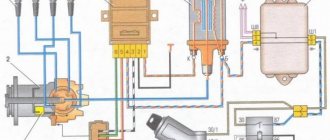
Electronic ignition connection diagrams: VAZ 2101-VAZ 2107
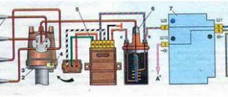
Scheme of a contactless ignition system for VAZ cars:
1 - switch; 2 — ignition coil (bobbin); 3 — distributor; 4 — ignition key; 5 - Hall sensor.
How contactless ignition works
The sequence and principle of operation of the BSZ is as follows:
- The driver turns the ignition key.
- The circuit is closed and constant voltage from the battery is supplied to the primary winding of the ignition coil. The energized primary winding forms a magnetic field around itself.
- When the starter starts, it begins to rotate the crankshaft of the internal combustion engine and rotates the shaft, which is located inside the distributor along with the slider.
- The hall sensor detects how the distributor shaft rotates (along the protrusion on the shaft) and transmits a signal to the switch.
- The electronic unit turns off the voltage supply to the primary winding based on the signal from the Hall sensor.
- When the voltage supply circuit is interrupted, at that moment a high voltage pulse of up to 24 kilovolts appears in the secondary winding of the coil, which is transmitted through a thick wire to the slider (the moving part of the distributor).
- Fixed contacts are built into the roof. The runner throws an impulse onto one of these stationary contacts. From the contact that received the high voltage pulse, it is transmitted through high-voltage wires to the spark plugs of those cylinders in which the pistons are at top dead centers.
- When voltage is applied to the spark plug, the working combustion chamber of the cylinder already contains fuel and air in a compressed state for ignition.
- The distributor slider rotates to spark all spark plugs according to a certain sequence pattern: 1-3-4-2. Depending on how to install the slider, the entire operation of the system depends, early ignition or later, we learned to determine in another material.
- The car engine starts.
ECMs are sometimes interchangeable, but sometimes they are not repairable.
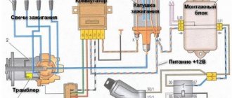
Diagram of an outdated VAZ ignition system (without switch)
1 — distributor (distributor); 2 - breaker; 3 - capacitor; 4 — ignition coil (bobbin); 5 - battery; 6 — ignition switch; 7 - spark plugs.
This scheme is in systems where there is no switch. The circuit is broken mechanically using a breaker.
Disadvantages of contact ignition:
- The contacts burn and oxidize, which reduces the power to create a spark.
- There are wear parts that are recommended to be changed every 20 thousand km. mileage
- Converted power in contact systems is up to 18 kilovolts. For electronic or contactless ones - up to 24 kilovolts.
Disadvantages of contactless ignition:
- The Hall sensor cannot be repaired. Working service life up to 50 thousand km. mileage
DIY installation and connection diagram
So, having made your choice, we suggest that you familiarize yourself with the necessary tools, the replacement procedure and video instructions.
Tool
From the tool you will need:
- Key 13 - remove and install distributor
- Screwdriver - tighten the screws.
- Drill with a metal drill, diameter for self-tapping screws
- Two self-tapping screws - screw the switch.
- Keys for 10 and 8 - remove and install the coil.
This is interesting: Increased oil consumption: reasons and how to deal with it
How to install step by step
- Disconnect the negative battery.
Before starting work on the ignition system, disconnect the negative terminal of the battery. - Remove the cover of the distributor with high-voltage wires.
Removing the ignition distributor cover - Disconnect the high voltage wire at the coil.
Disconnecting the wire from the ignition coil - Using short turns of the starter, set the ignition distributor slider perpendicular to the engine.
This is how the distributor should be installed relative to the motor - Mark the position of the distributor with a marker on the engine.
Installing the ignition distributor slider - Unscrew the nut holding the distributor using a 13mm wrench. Disconnect the wire connecting the device to the coil.
Before removing the ignition distributor, disconnect the wire that goes to it from the coil - Insert the new ignition distributor into the engine by removing the cover.
The ignition distributor must be inserted into the standard socket - Turn the distributor body so that the middle mark on it coincides with the mark you previously placed on the motor.
- Tighten the nut securing the new ignition distributor.
The ignition distributor is held in place by a nut - Put on the distributor cover and connect the wires to it.
This is how the cover is installed on the distributor - Replace the ignition coil with a new one.
A new system requires a new coil - Connect the original and new wires to the coil. To connect everything correctly, use the diagram.
All connections must comply with the diagram - Install the switch in any convenient location. Drill holes and screw screws into them to hold the device. Check the connection of all VAZ-2106 systems.
The switch will not take up much space under the hood and its location does not matter - Start the engine. If it doesn’t start the first time, you can turn the distributor a little. This will change the ignition timing.