Division by function
As for functions, all electrical equipment is divided into systems that perform specific tasks:
- Take part in the operation of the engine;
- Ensure traffic safety;
- Create comfortable conditions;
There are also systems that are aimed at maintaining the functionality of the electrical circuit itself.
Systems responsible for engine operation
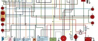
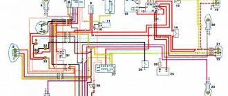
The ignition system takes part in the operation of the power unit and its task is to generate a spark in the engine cylinders to ignite the air-fuel mixture. The components of this system are a switch, a spark torque sensor, a coil and spark plugs. The system is turned on using the ignition switch. All of these components are connected by one circuit, the diagram of which is shown below:
The second system related to electrical equipment and working with the engine is the starting system. To start the engine, a power electric motor is used - a starter, controlled from the same ignition switch. Its scheme is as follows:
The cooling system fan is also related to the engine.
Systems responsible for safety and comfort
Electrical equipment that ensures traffic safety includes:
- Light and sound alarm (turn signals, brake lights, reversing lights, sound signal);
- Main light (headlights, PTF);
- Heaters, glass cleaners and washers;
These devices are combined into several systems. Below is the power supply diagram for only one of them - the turn signals:
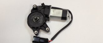
Since the Oka is a budget car, there are not so many electrical appliances that create comfortable conditions for the driver. These include a stove (which includes an electric fan motor), an interior lamp and a cigarette lighter.
Note that the stove, in addition to creating convenience, also affects traffic safety - it heats the windows in winter.
Since devices responsible for traffic safety and comfort are not always in demand, they are turned off by default and are activated using switches.
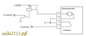
The on-board network also includes a battery recharging system, that is, a component whose task is to maintain the functionality of electrical equipment. Its connection diagram is as follows:
Malfunctions
Since the generator on the Oka has a conventional design and does not differ from the devices of other cars (and model 37.3701 is completely “borrowed” from the “older” VAZ cars), then the faults of the unit are of the same type. In general, the unit itself is quite reliable and has proven itself, but it cannot do without breakdowns. Conventionally, generator malfunctions are divided into mechanical and electrical. The first include:
- Bearing wear;
- Damage and destruction of covers;
- Wear of brushes and slip rings;
- Large wear on the working surfaces of the pulley;
Elimination of these breakdowns is carried out by replacing damaged or worn components.
There are more electrical breakdowns and they are more serious. These include:
- Short circuit and breaks in the stator windings;
- Broken wires on the collector;
- Breakdown of rectifier diodes;
- Regulator malfunction;
Some types of these breakdowns are quite difficult to eliminate, and sometimes a more expedient option for restoring the functionality of the unit is to replace the generator. This usually concerns problems associated with windings - their breaks, short circuits. Otherwise, repairs come down to installing new parts to replace faulty ones.
Checking generator operation
You can check the functionality of the generator in several ways using certain methods, for example: you can check the output current of the generator, the voltage drop on the wire that connects the current output of the generator to the battery, or check the regulated voltage.
To check, you will need a multimeter, a car battery and a lamp with soldered wires, wires for connecting between the generator and the battery, and you can also take a drill with a suitable head, since you may have to twist the rotor by the nut on the pulley.
Basic check with a light bulb and multimeter
Connection diagram: output terminal (B+) and rotor (D+). The lamp must be connected between the main output of the generator B+ and contact D+. After this, we take the power wires and connect the “minus” to the negative terminal of the battery and to the generator ground, the “plus”, respectively, to the plus of the generator and to the B+ output of the generator. We fix it on a vice and connect it.
We turn on the tester in DC mode, attach one probe to the battery to “plus”, and the second one too, but to “minus”. Next, if everything is in working order, then the light should light up, the voltage in this case will be 12.4V. Then we take a drill and start turning the generator, accordingly, the light bulb will stop burning at this moment, and the voltage will already be 14.9V. Then we add a load, take an H4 halogen lamp and hang it on the battery terminal, it should light up. Then we connect the drill in the same order and the voltage on the voltmeter will show 13.9V. In passive mode, the battery under the light bulb gives 12.2V, and when we turn it with a drill, it gives 13.9V.
Generator test circuit
Strictly not recommended:
- Check the functionality of the generator by short circuit, that is, “to spark”.
- It is also undesirable to allow the generator to operate without consumers turned on; it is also undesirable to operate with the battery disconnected.
- Connect terminal “30” (in some cases B+) to ground or terminal “67” (in some cases D+).
- Carry out welding work on the car body with the generator and battery wires connected.
General design
Since model 37.3701 is the most common, we will consider it in the future, but almost all the information is relevant for other types of generators.
The design of the generator is standard for this type of device; the unit consists of:
- Rotor (with slip rings);
- Stator;
- Covers (front, back);
- Pulley (with impeller);
- Voltage regulator (also includes a brush holder with brushes);
- Capacitor;
- Rectifier.
The design also includes rotor bearings and tie bolts, which assemble the unit into a single unit. In general, the generator circuit is standard and does not stand out in any way.
The unit belongs to the attached equipment of the power plant; it is installed on the left in the lower part of the engine compartment on the left in front of the engine. Fastening at the bottom of the unit is carried out by bolting through lugs, and at the top - using a strip.
The generator is driven from the crankshaft via a belt drive . The Oka generator belt is V-shaped, and it drives only this unit. The drive tension is adjusted by moving the device along the adjustment bar.