Tightening torques for threaded connections
| Detail | Thread | Tightening torque, N m (kgf m) |
| Engine | ||
| Cylinder head bolts | M12x1.25 | see section "Engine" |
| Intake pipe mounting nut | M8 | 20,83-25,73 (2,13-2,63) |
| Tension roller nut | M10×1.25 | 33,32-41,16 (3,4-4,2) |
| Camshaft bearing housing nut | M8 | 18,33-22,64 (1,87-2,3) |
| Camshaft pulley bolt | M10×1.25 | 45,82-56,6 (4,68-5,78) |
| Accessory drive housing bolt | M6 | 6,66-8,23 (0,68-0,83) |
| Cooling jacket outlet pipe mounting nut | M8 | 9,8-22,5 (1,0-2,3) |
| Main bearing cap bolt | M10×1.25 | 68,31-84,38 (6,97-8,61) |
| Oil sump bolt | M6 | 5,1-8,23 (0,52-0,84) |
| Balance shaft gear bolt | M10x1.25 | 45,82-56,6 (4,68-5,78) |
| Connecting rod cover nut | M9x1 | 43,32-53,51 (4,42-5,46) |
| Flywheel bolt | M10×1.25 | 70,81-87,47 (7,22-8,92) |
| Water pump mounting bolt | M6 | 5,10-8,23 (0,52-0,84) |
| Crankshaft pulley bolt | M12x1.25 | 87,47-108,05 (8,93-11,03) |
| Water pump inlet pipe mounting bolt | M6 | 4,2-5,1 (0,43-0,52) |
| Muffler exhaust pipe fastening nut | M8x1.25 | 19,6-24,5 (2,0-2,5) |
| Bolts for securing the front and rear suspension brackets of the power unit | M10×1.25 | 31,85-51,45 (3,25-5,25) |
| Nuts of bolts securing the suspension supports of the power unit | M10x1.25 | 28,08-45,3 (2,86-4,62) |
| Nuts for fastening the left suspension bracket of the power unit | M8 | 14,0-22,54 (1,43-2,3) |
| Bolt securing the oil receiver to the main bearing cover | M6 | 6,37-10,29 (0,65-1,05) |
| Bolt securing the oil receiver to the pump | M6 | 6,37-10,29 (0,65-1,05) |
| Oil pump mounting bolt | M6 | 8,33-10,29 (0,85-1,05) |
| Oil pump housing bolt | M6 | 6,97-8,61 (0,71-0,88) |
| Oil pump pressure reducing valve plug | M1bx1.5 | 45,5-73,5 (4,6-7,5) |
| Oil filter fitting | M20x1.5 | 37,49-87,47 (3,82-8,92) |
| Carburetor mounting nuts | M8 | 6,6-15,4 (0,7-1,6) |
| Clutch | ||
| Bolt securing the clutch housing to the engine cylinder block | M12x1.25 | 54,2-87,6 (5,5-8,9) |
| Clutch housing cover bolt | M6 | 4,7-7,7 (0,49-0,79) |
| Nut securing the clutch housing to the gearbox housing | M8 | 15,7-25,5 (1,6-2,6) |
| Bolt securing clutch to flywheel | M8 | 19,1-30,9 (1,95-3,15) |
| Transmission | ||
| Hinge bolt on gear selector rod | M8x1 | 16,3-20,1 (1,66-2,05) |
| Gear selector mounting bolt | M6 | 5,1-8,2 (0,5-0,83) |
| Nut securing the gear shift rod clamp | M8 | 15,7-25,5 (1,6-2,6) |
| Nut of the rear end of the primary and secondary shafts | M20x1.5 | 120,8-149,2 (12,3-15,2) |
| Reversing light switch | M14×1.5 | 28.4-45.3 (2.9-4.b) |
| Bolt securing the gear fork to the rod | M8x1 | 11,7-18,6 (1,2-1,9) |
| Nut fastening the jet thrust to the power unit | M10x1.25 | 51-82,4 (5,2-8,4) |
| Speedometer drive fastening nut | M6 | 4,5-7,2 (0,45-0,73) |
| Ball joint race fastening nut | M8x1.25 | 15.9-25.8 (1.6-2.b) |
| Gear selector shaft mounting bolt | M6 | 7,8-12,3 (0,8-1,26) |
| Nut securing the rear crankcase cover | M8x1.25 | 15,7-25,5 (1,6-2,6) |
| Retainer plug | M16x1.5 | 28,4-45,3 (2,9-4,6) |
| Attaching the gear selector lever to the rod | M8x1 | 28,4-35,0 (2,9-3,6) |
| Nut securing the gearbox to the clutch housing | M8x1.25 | 15,7-25,5 (1,6-2,6) |
| Drain plug | M22x1.5 | 28,7-46,3 (2,9-4,7) |
| Clutch fork support | M8 | 15,7-25,5 (1,6-2,6) |
| Clutch release bearing guide bushing bolt | M6 | 3,8-6,2 (0,39-0,63) |
| Front suspension | ||
| Nut securing the upper support to the body | M8 | 19,6-24,2 (2,0-2,47) |
| Nut securing the ball joint to the suspension arm | M12x1.25 | 77,3-96 (7,9-9,8) |
| Bolt securing the ball joint to the steering knuckle | M10x1.25 | 49-61,7 (5,0-6,3) |
| Nut securing the lever to the subframe | M10×1.25 | 59,7-73,5 (6,0-7,5) |
| Nut securing the extension to the lever | M12×1.25 | 102,9-127 (10,5-13,0) |
| Telescopic stand housing nut | M48x1 | 117,5-147 (12-15) |
| Nut securing the brace to the subframe | M14x1.5 | 117,5-147 (12-15) |
| Nut securing the stabilizer to the lever | M10x1.25 | 42-52 (4,29-5,3) |
| Nut securing the stabilizer to the subframe | M8 | 12,9-15,9 (1,32-1,63) |
| Nut securing the telescopic rod rod to the upper support | M12x1.25 | 52,6-64,6 (5,35-6,6) |
| Nut securing the strut to the steering knuckle | M12x1.25 | 103-127,2 (10,5-13,0) |
| Nut securing the left side member of the subframe | M8 | 19,6-24,2 (2,0-2,47) |
| Bolt securing the subframe to the body | M12x1.25 | 83-103 (8,5-10,5) |
| Steering | ||
| Steering gear housing clamp nut | M8 | 15,0-18,6 (1,5-1,9) |
| Steering shaft bracket mounting nut | M8 | 15,0-18,6 (1,5-1,9) |
| Bolt securing the steering shaft to the gear | M8 | 15,0-18,6 (1,5-1,9) |
| Steering wheel nut | M16x1.5 | 31,4-51 (3,2-5,2) |
| Locknut for outer steering linkage | M12x1.25 | 27,0-33,4 (2,8-3,4) |
| Bolt securing the connector to the subframe | M8x1.25 | 19,6-24,2 (2,0-2,47) |
| Steering rod ball pin nut | M12x1.25 | 27,05-33,4 (2,76-3,41) |
| Brake system | ||
| Bolt securing the wheel cylinder to the brake shield | M6 | 3,31-7,72 (0,34-0,78) |
| Front wheel hub nut | M20x1.5 | 186,3-225,6 (19-23) |
| Bolt securing the shoe guide to the steering knuckle | M10×1.25 | 49-62 (5,0-6,3) |
| Bolt securing the caliper to the guide pin | M8 | 31-38 (3,16-3,87) |
| Rear brake to axle bolt | M10×1.25 | 34,3-42,6 (3,5—4,3) |
| Nut securing the master cylinder to the vacuum booster | M8 | 9,8-15,7 (1.0-1.6) |
| Nut securing the vacuum booster to the bulkhead | M8 | 9,8-15,7 (1,0-1,6) |
| Nut securing the pressure regulator to the body | M6 | 3,31-7,72 (0,34-0,79) |
| Manual brake lever lever bolt | M8 | 10,36-24,18 (1,06-2,47) |
| Rear suspension | ||
| Nut securing the lower end of the shock absorber | M10x1.25 | 50-61,7 (5,1-6,3) |
| Rear suspension arm mounting nut | M10x1.25 | 50-61,7 (5,1-6,3) |
| Nut of fastening of the left bracket of the suspension arm | M10x1.25 | 27,4-34 (2,8-3,5) |
| Shock absorber rod mounting nut | M10x1.25 | 50-61,7 (5,1-6,3) |
| Wheel nut | M12x1.25 | 77,5-96,1 (7,9-9,8) |
| Bolt securing the wheel axle to the suspension arm | M10x1.25 | 42,1-52 (4,29-5,3) |
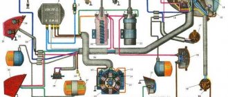
| Electrical equipment | ||
| Spark plug | M14×1.25 | 30,7-39 (3,13-4,0) |
| Nut of the bolt securing the generator to the bracket | M12x1.25 | 58,3-72,0 (5,9-7,3) |
| Nut of the stud securing the generator to the adjusting bar | M10×1.25 | 28,1-45,3 (2,9-4,6) |
| Starter mounting bolt | M10x1.25 | 22,3-52,0 (2,3-5,3) |
1. The given torque values can be rounded to tenths within the tolerance.
2. The cylinder head bolts must be tightened in four steps:
- 1 - torque 20 N m (2 kgf m);
- 2 - torque 69.4-85.7 N m (7.1-8.7 kgf m);
- 3 - turn 90°;
- 4 - turn it 90° again.
3. For other threaded connections, use the following tightening torques, N m (kgf m):
- M6 - 6-8 (0.6-0.8);
- M8 - 14-18(1.4-1.8);
- M10 - 28-36 (2.8-3.6);
- M12 - 50-62 (5.0-6.2).
Correct tightening order
There is a certain order for tightening the bolts; it is the same on almost all cars - from the center of the head to its edges, cross to cross. So, for example, the two central bolts of the right and left rows are tightened first, then the two bolts located to the left of the central ones, then the two to the right of the central ones, then the two bolts located on the left in both rows, and the bolts located on the right in both rows complete the order.
It is important to remember that fastening is always performed in three to four approaches:
- The first approach is a force of 3-4 kgf.
- The second approach is a force of 7 kgf.
- The third approach is a force of 9 kgf.
- The last approach is a force of 11.5 - 12 kgf.
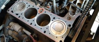
Replacing the cylinder head gasket
If a leak of engine oil or coolant is detected at the junction of the cylinder head with the cylinder block, remove the head and replace its gasket. A leak can also occur due to warping of the block head due to overheating.
Torque wrench, hexagons “5” and “10”, keys “10”, “13” and “17”, screwdriver.
The head gasket is a one-time use, so each time the head is removed, the gasket must be replaced.
1. Disconnect the wire from the “–” terminal of the battery.
2. Set the piston of the 1st cylinder to the TDC position of the compression stroke (see “Installing the piston of the 1st cylinder to the TDC position of the compression stroke”).
3. Drain the coolant (see “Replacing the coolant”).
4. Remove the air filter (see subsection “Power system”).
5. Remove the shell of the air damper drive rod from the bracket and disconnect the rod from the lever by loosening the fastening bolts.
6. Disconnect the intermediate rod end from the intermediate throttle actuator lever.
]
7. Unscrew the two nuts securing the intermediate arm bracket.
Please note: there are spring washers under the nuts.
8. Remove the bracket from the studs.
9. Disconnect the wires from the idle air control valve.
10. Remove the pulley from the camshaft (see “Replacing the camshaft oil seal”).
11. Remove the cylinder head cover (see “Cleaning the crankcase ventilation system”).
12. Disconnect the hose from the spark torque sensor vacuum regulator.
13. Unscrew the three nuts securing the spark torque sensor, remove it from the studs and move it to the side without disconnecting the block with wires from it.
14. Unscrew the two nuts securing the fuel pump, remove the washers, remove the pump from the accessory drive housing studs and move it to the side without disconnecting the hoses from it.
15. Remove the bolt securing the auxiliary drive housing.
16. Remove the accessory drive housing from the studs.
17. Unscrew the nut of the upper fastening of the rear cover of the camshaft drive belt.
18. Remove the camshaft bearing housing (see “Replacing valve stem seals”).
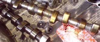
19. Take out the camshaft and remove the oil seal from it.
20. Loosen the nut securing the generator to the tension bar.
21. Unscrew the nut securing the tension bar to the cylinder block and remove the flat washer installed under it.
22. Remove the eye from the hairpin...
23. ... and the tension bar.
24. Remove the tension roller and spacer ring (see “Replacing the tension roller”).
25. Loosen the clamps and disconnect the three hoses from the cooling jacket pipe.
26. Slide the protective cap and disconnect the wire from the coolant temperature gauge sensor.
27. Loosen the clamps and disconnect vacuum hose 1 (to the vacuum booster) and hose 2 for heating the intake pipe from the intake pipe fittings.
28. Loosen the clamp and disconnect the fuel supply hose from the fuel pump to the carburetor.
29. Unscrew the two nuts securing the exhaust pipe of the muffler on the left side of the head and.
thirty. . two nuts securing it on the right side of the head.
31. Remove the six cylinder head bolts and remove the bolts and washers.
32. Press the rear camshaft drive belt cover until the pin comes out of its hole.
33. Remove the head from the cylinder block by removing the pins from the holes in the muffler exhaust pipe flanges.
34. Remove the gasket.
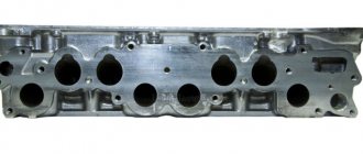
35. Clean the mating surfaces of the cylinder block and head.
36. Remove oil from the threaded holes in the cylinder block for the head bolts.
37. Blow out the jet in the oil channel of the cylinder block with compressed air.
38. . block cylinders.
39. Thoroughly wipe the cylinder mirrors and the mating surface of the cylinder block with a clean rag.
40. Install a new gasket on the cylinder block.
The gasket must be clean and dry.
41. Thoroughly wipe the mating surface of the block head with a clean rag.
42. Install the head on the block, placing the exhaust pipe flanges of the muffler onto the head studs.
43. Measure the length of the cylinder head bolts, as they stretch out with repeated use. Replace bolts longer than 135.5 mm with new ones.
44. Lubricate the head bolts and washers with a thin layer of engine oil.
45. Tighten the head bolts in the indicated sequence in four stages:
1st - torque 20 N m (2 kgf m);
2nd - torque 69.4–85.7 N m (7.1–8.7 kgf m);
3rd - turn 90°;
4th - finally turn it 90°.
46. Thoroughly dry the camshaft with a clean cloth.
47. Lubricate the camshaft journals and cams with a thin layer of engine oil.
48. Install the camshaft into the cylinder head so that the valve drive cams of the first cylinder are directed upward from the valve tappets.
49. Apply sealant to the surface of the block head in the areas where the bearing housing contacts.
50. Install the camshaft bearing housing.
51. Tighten the bearing housing nuts in the order shown in two stages:
1st - tighten the nuts until the bearing housing touches the surface of the cylinder head; 2nd - finally tighten the nuts to a torque of 21.6 N m (2.2 kgf m).
52. Press in the camshaft oil seal (see “Replacing the camshaft oil seal”).
53. Install the parts on the head and connect hoses and wires to it in the reverse order of removal.
54. Install the camshaft drive belt (see “Replacing the camshaft drive belt”).
55. Check and, if necessary, adjust the clearances in the valve drive (see “Adjusting the clearances in the valve drive”).
Is it possible to properly tighten cylinder head threaded connections without a torque wrench?
Tightening threaded connections in the absence of the appropriate equipment is absolutely not worth it for car enthusiasts who decide to independently change the head gasket or grind the valves.
Experienced repairmen who are able to feel in practice the strength limit of any bolt do not always use a torque wrench when tightening. But such ability does not come immediately. To do this, you need to work with torque wrenches for several years.
But even experienced specialists tighten the cylinder head bolts on expensive brands of passenger cars with a torque wrench, because this operation directly affects the longevity of the power unit. In an emergency situation, when it is not possible to use a torque wrench, you can use the option with a mechanical or electronic cantor. In the video below, an experienced mechanic explains to viewers how to properly tighten a cylinder head without a key. It is worth keeping in mind that the correctness of the work should be checked using a protractor.
Removal and repair of the cylinder head of the Oka car
The only model of a particularly small class, equipped with a two-cylinder engine, which was produced by the Volzhsky Automobile Plant (as well as SeAZ and KamAZ) was the VAZ Oka and its modifications.
Despite the fact that there were only two cylinders, conceptually the engine of this car was no different from the engines of other versions of the VAZ. It was a well-developed power plant with liquid cooling, electronic ignition, and a timing belt with an overhead camshaft. shaft and belt drive, carburetor power system. The Oka power unit differed from the engine of the same VAZ-2108, in fact, only in the number of cylinders. This means that this installation required the same maintenance as the “eight” one.
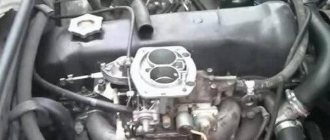
Features of the Oka engine
In fact, the Oka engine differs from the internal combustion engine of the VAZ 2108 model only in the number of cylinders. Thus, the power unit of this baby requires exactly the same maintenance as the internal combustion engine of the G8. The main feature of the Oka engine is that the cylinder head plays a serious role in its operation, since with small dimensions it performs the same functions as the cylinder head of the VAZ 2108, namely, it participates in the systems:
- Power supply and exhaust gas removal.
- Cooling.
- Ignition.
The Oka cylinder head is also responsible for maintaining valve timing. In general, the performance of the internal combustion engine depends on the condition of the cylinder head and its components, therefore it is necessary to regularly maintain its components:
- Adjust valves.
- Replace oil seals.
In the event of failure, the cylinder head must be repaired, the complexity of which depends on the nature of the failure.
When is it necessary to dismantle the cylinder head?
Note that it is impossible to repair the Oka head while it is installed on the engine, so the first operation to restore this element is to remove it from the engine. Despite the fact that the cylinder head is located at the top of the power plant, it is not very easy to dismantle it, since many components are attached to it. It will also have to be removed if the head gasket needs to be replaced.
Basically, repair of the Oka 11113 cylinder head or other modification is performed if problems arise with the valve assembly:
- Burnout of valves;
- Wear of valve seats and edges, their burning;
- Damage or wear of guides and valve stem seals;
These are the main reasons that require repair work. There are other reasons why the cylinder head has to be removed and repaired, for example, the appearance of a crack in the body, but such a malfunction is very rare.
Also, removal of the cylinder head will be required if the cylinder-piston group is replaced, since the pistons are pulled upward from the cylinders.
When is it necessary to tighten the cylinder head?
The need to periodically tighten the cylinder head is typical only for car brands that were produced up to 2010 inclusive. All other models of modern cars have a completely different engine structure, as a result of which this stage of work is not carried out. However, for those who own the same VAZ-2106 or 2107, this problem is primarily relevant during the car’s annual maintenance.
Advice: when repairing the ignition switch on a VAZ-2107, be sure to check the further operation of the engine. Replacing any element related to the operation of the engine greatly affects the condition and operation of the cylinder heads.
The need to tighten the cylinder block arises as a result of the gradual accumulation of water in the place where the bolts come into contact with the cylinders in the block. In this case, the main reason lies in correcting problems with lubricant leakage. After all, if oil begins to leak a little from the engine housing, then within a couple of months you will encounter problems with the operation of the engine cylinders.
Tool
Let us note that when dismantling the head from the motor, although you have to unscrew and remove a lot of things, this work can be done in a garage yourself, having only the basic tools at hand, no specific keys or devices are required.
Removing the "Oka" head is done using:
- A set of wrenches (open-end, socket, socket, heads with knobs);
- set of hexagons;
- Screwdrivers;
- Rags;
- Coolant collection container;
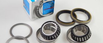
You will also definitely need a new cylinder head gasket, since it is disposable, and no matter what purpose the head is removed, the head gasket must be replaced. Additionally, you will need a valve cover gasket and camshaft seals. shaft and gaskets for exhaust pipes and intake manifold.
Note that the complexity of dismantling largely depends on why exactly the cylinder head is being removed. If you just need to replace the gasket under it, then you won’t have to disassemble very much. If it is removed, in order to disassemble the head and carry out repairs, you will have to dismantle more elements. Full disassembly instructions will be described below, but simple disassembly will also be mentioned.
Video - Repairing Oka, replacing the cylinder head gasket
Repairing auto parts yourself is a responsible task that should be taken as seriously as possible. Sometimes a faulty spare part takes the driver by surprise, forcing him to spend a lot of time and money searching for a good service station, but there is an alternative solution to the problem; this requires a small amount of knowledge and a set of tools.
When repairing Appendix 1. tightening torques of threaded connections of the VAZ “OKA” 1111 1988-2008, you need to be extremely careful and not neglect the little things. To get acquainted with the issue, car enthusiasts often use various Internet portals dedicated to auto parts. Some of them use narrowly focused forums. But, as a rule, only generalized information is provided there, which is known initially. Where can you find a reliable source that offers really useful things? Our portal is open for this 24 hours a day. Online mode allows us to help clients at any time convenient for them. Moreover, a mobile version has been developed that is available to everyone.
A detailed description of such a unit as Appendix 1. Tightening torques for threaded connections of the VAZ “OKA” 1111 1988-2008 has a good structure with thematic headings. In addition, there is always the opportunity to familiarize yourself with the intricacies of installation. There are often situations when a driver is confident in his abilities, but when he gets down to work, questions begin to arise. Thanks to our portal, such moments can be easily avoided. The site is a database that is updated regularly. By using it as a support during repair work, the car enthusiast receives a serious advantage. Each of the articles has reliable support, tested in practice.
In addition to the repair manual, the owner of a personal car will be able to prevent a lot of breakdowns that occur due to the human factor, thanks to the information located on the site. Users are presented with a lot of useful recommendations for proper operation, which will help significantly extend the life of the unit and avoid many negative consequences.
Online support is an excellent and most convenient way to obtain the necessary information. Another significant plus is that articles are written for people. We understand that the reader will do everything with his own hands, and we try to make it as convenient and efficient as possible. Use the resource at any time of the day and find the answer to any question you may have regarding cars.
Procedure
Having stocked up with everything you need, you can begin work.
The sequence of actions is as follows:
- We put the Oka in the garage or on a flat area, immobilize it, remove the terminal from the battery;
- We drain the coolant from the cooling system (place a container under the drain plugs, unscrew them and wait until the liquid drains. Replace the plugs and tighten them);
- Remove the air filter housing. Cover the carburetor neck with a rag. We disconnect the throttle and air damper cables from it, remove the gas drive mechanism with the lever and its mounting bracket, as well as the fuel pipes and the wire of the XX solenoid valve;
- Remove the protective cover of the timing drive. We install marks on the crankshaft and camshaft. shaft (this is especially important during partial disassembly);
- Loosen the tension roller so that it loosens the tension of the drive, and remove the belt from the camshaft wheel;
- Disconnect the fuel pipe from the fuel pump. Unscrew the pump fasteners and remove it;
- We disconnect the pipes from the valve cover, unscrew its fastening and remove it;
- We unscrew the nuts of the spark torque sensor, disconnect the wires from it, and move it to the side. We also remove the high voltage wires from the spark plugs;
- Unscrew the mounting bolt of the auxiliary units housing;
- We unscrew the fastening bolt of the camshaft gear and tighten it (carefully so as not to miss the key).
We also dismantle the tension roller; - At the top, unscrew the fasteners of the rear timing drive cover and bend it to the side;
- We unscrew the nuts securing the exhaust pipes and pull them off the studs;
- We remove the pipe from the vacuum regulator;
- Unscrew the top bar used to tension the alternator belt;
- Disconnect the cooling system pipes coming to the head;
- Then it all depends on why the cylinder head is removed. If you only plan to replace the head gasket, then there is no need to dismantle anything further. We simply unscrew the cylinder head mounting bolts and remove it from the block along with the installed camshaft and intake manifold, change the gasket and put everything back together. In this case, after assembly work, valve adjustment will not be required, since the camshaft. the shaft was not removed. But if everything is dismantled for repairs, for example, it is planned to replace valves at Oka, then we do not unscrew the fastening bolts yet, but continue to disassemble further;
- Unscrew the camshaft bearing cover and remove it;
- We remove the camshaft;
- And only after that we unscrew the cylinder head mounting bolts, after which we dismantle it from the car;
And then repair work is already being carried out. But to do this, the intake manifold is first disconnected from the head. Then the pushers are removed along with the adjusting washers. Further, for disassembly, you will need a device for drying and drying the valves in order to remove them, after which repair work is carried out - replacing the valve guides, the valves themselves, grinding them in, etc.
Instructions
Despite the fact that removing the GBU in Oka is a very labor-intensive process, the work can be done in a garage. So, if you decide to repair or service your Oka car yourself, you will need the following tools:
- A set of wrenches (socket, socket, open-end, heads with knobs).
- Hexagon set.
- Rags.
- Screwdrivers.
- Container for collecting antifreeze (antifreeze).
Do not forget about the new cylinder head gasket - this is a disposable consumable, and even if it is in good condition, when dismantling the cylinder head (for whatever reason), a new gasket is always installed. Additionally, you will need camshaft seals, a valve cover gasket, as well as gaskets for the intake manifold and exhaust pipes.
The complexity of the cylinder head removal procedure depends largely on the purpose for which the dismantling is performed. If you only need to replace the head gasket, you won't have to disassemble much. If the cylinder head is dismantled to repair it, there will be much more work.
Procedure
Having prepared everything you need, you can proceed directly to removing the cylinder head.
- We place the car on a flat surface, secure it with the parking brake (you can additionally place something under the wheels so that the car does not roll during the work) and disconnect the battery.
- Pour the antifreeze into a container prepared in advance. (Here you need to wait until all the coolant has flowed out and then screw the plugs tightly into the drain holes).
- Remove the air filter housing.
- Cover the carburetor neck with a rag, disconnect the air and throttle valve cables and remove the gas drive mechanism along with the lever and the bracket that secures it.
- You will also need to remove the fuel wire of the XX solenoid valve and pipes.
- Remove the protective cover for the timing drive.
- We put marks on the camshaft and crankshaft (it is especially important to do this during partial disassembly).
- We loosen the tension of the roller so that the timing belt can easily be thrown off the camshaft wheel.
- We disconnect the fuel pipe from the fuel pump and unscrew the pump mounting bolts and remove it.
- Disconnect the pipes from the valve cover, unscrew the fasteners and remove it.
- We unscrew the nuts from the spark torque sensor, disconnect the wires, and move it to the side. You also need to remove the high voltage wires from the spark plugs.
- We unscrew the mounting bolt from the housing of the auxiliary units.
- We unscrew the mounting bolt from the camshaft gear, then carefully, so as not to drop the key, tighten it.
- Remove the tension roller.
- We unscrew the fastening bolt of the rear cover of the toothed belt drive and bend it to the side.
- We unscrew the fastening nuts of the exhaust pipes and carefully pull them off the studs.
- We remove the vacuum regulator pipe.
- Unscrew the top tension bar of the generator belt.
- Disconnect the cooling system pipes leading to the head.
Further actions depend on the purpose for which the cylinder head is dismantled. If you only need to replace the gasket, then nothing else needs to be disassembled. All that remains is to unscrew the cylinder head fasteners and remove it from the block along with the camshaft and intake manifold, replace the gasket and reassemble everything in the reverse order.
In this case, adjustment of the valves after assembly will not be necessary, since the camshaft was not removed. If dismantling is carried out for repairs, then before unscrewing the cylinder head mounting bolts, you need to unscrew and remove the camshaft bearing cover and remove it. Only after this can the cylinder head be removed.
Next, the intake manifold is disconnected from the head, the pushers and adjusting washers are removed. For subsequent disassembly (removing valves) you will need a desiccant. Now you can carry out the necessary repair work.
Assembly Features
After restoration, the head is installed in place (don’t forget to replace the cylinder head gasket), and everything is put back together. But there are some nuances during assembly, and the most important of them is the order in which the cylinder head is tightened. If this is not followed, there is a high probability that the head will not be seated securely, it may move, or the gasket will break.
The procedure for tightening the block head bolts on the Oka is shown in the photo:
We also note that tightening is performed in several approaches and always using a torque wrench:
- Tighten all the bolts in the specified order, creating a force of 20 N/m;
- In the second approach, the force should be 70-85 N/m;
- Carrying out the third approach, turn the bolts 90 degrees;
- The last approach is to turn it 90 degrees again;
During the assembly process, we also pay attention to the condition of the camshaft seals. shaft and, if necessary, replace them.
Tightening torque of cylinder head VAZ 2114 8 valves: useful video
You can glean additional useful information from the video below:
Well, in the end, we should once again remind you that before you start tightening, you need to check the length of all bolts (it should be 135.5 mm). If the length differs from the specified one, especially upward, then even the most careful tightening of such bolts will make no sense.
- Changing the thermostat on a VAZ 2114 with your own hands
- We clarify how to check the cylinder head gasket of a VAZ 2114
- Which oil is better to pour into the VAZ 2114 engine
Thank you. Very useful information.
Why is the cylinder head of the classics in the photo? And what does 2 kg/cm2 mean? When did this moment begin to be measured in atmospheres?
VAZ 1111 1988-2003: Cylinder head VAZ 1111 OKA
| You will need | |
| |
Before starting work
Remove the head from the cylinder block ( see subsection 10.4.1. ) and clean it.
Tool for removing caps:
With increased clearance in the valve drive, a characteristic knock appears, usually at regular intervals (its frequency is less than any other knock in the engine). If adjusting the clearances in the valve drive does not produce positive results, check the condition of the camshaft and the supporting surfaces under the camshaft journals.
Errors when installing the head
If you do not use a torque wrench when installing the cylinder head, you may make a mistake with the force, which will lead to uneven torque. In such cases, there will be excessive or insufficient force, which will result in either deformation of the head surface or allow the breakthrough of gases, oil or coolant. In both cases, this is fraught with serious consequences for the engine.
If you follow the rules for tightening the fastening bolts, as well as the required torque, you can always count on reliable and durable operation of the installed parts. The gas distribution mechanism in the engine plays a major role, so you should not neglect the rules for installing the component elements.