Timing phases and when to set them according to marks
Valve timing refers to those moments at which the piston in the engine moves up and down over a certain interval.
When irregularities in the valve timing occur, the pistons move incorrectly along the interval, resulting in uneven engine operation on the VAZ-2107. If the driver notices that the car’s power decreases, fuel consumption increases, and engine interruptions occur, then it is necessary to resort to setting the valve timing according to marks. How to set marks on a VAZ 2107 carburetor and injector, we will learn from this material, since the design of the timing mechanism is identical.
How to set timing timing marks
The procedure involves performing the following manipulations:
- The VAZ 2107 needs to be placed on a hard surface, with chocks placed under the wheels and the hand brake pressed all the way. The gear shift lever must be set to neutral mode.
- The cover is removed from the cylinder head by first unscrewing all the fixing nuts to “10”. It is better to replace the gasket with a new one, even if the old one shows no signs of damage.
- Using a key set to “24”, you need to turn the crankshaft on a VAZ 2107 car. This is done in order to be able to align the marks on the moving and stationary parts of the mechanism. To carry out these actions, it is recommended to use good lighting or use a flashlight. The crankshaft rotates until the mark on the pump and generator drive belt pulley coincides with the long mark marked on the block.
- Combining these risks, the mark on the sprocket should eventually coincide with the ebb on the camshaft bed. If the mark ends up at the bottom, then you should rotate the crankshaft 360 degrees.
- If you can’t make sure the labels match, then proceed to the next steps, which are described below.
- The crankshaft is rotated until the marks on the star and the bed ebb align.
- Using the key at “13”, you need to loosen the tensioner. The 2 nuts securing the tensioner are unscrewed, after which this device is removed.
- The bolt that secures the sprocket to the camshaft is unscrewed. To do this you will need to use the key at “17”.
- The sprocket is removed, after which it must be rotated until the marks on the VAZ-2107 timing belt pulley coincide with the long mark on the block. The star fastening bolt does not need to be unscrewed, since after removing the tensioner the camshaft star rotates.
- We put a chain on the sprocket, if it was decided to unscrew it, and install it in place. Finally, the tensioner is installed, for which you should tighten it with 2 nuts to “10”. You can install the tensioner first, but later you will need to use a crowbar or pry bar to get the sprocket into place. Finally, screw the tensioner nut to “13”.
This relative arrangement of the parts allows the piston of the 4th cylinder to be positioned at top dead center TDC.
Features of servicing the timing mechanism
After the timing marks are installed on the VAZ-2107, you need to perform the following actions:
- The timing chain of the VAZ-2107 is being tensioned.
- Adjusting the valves, or more precisely, the thermal gap between the camshaft cams and the rocker arm.
- Setting up the ignition system.
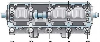
The process of adjusting the valves on the VAZ-2107 is carried out according to the following scheme: initially 6 and 8 valves are adjusted, the report must be carried out from the radiator. After they are adjusted, you need to start adjusting valves 4 and 7, then valves 1 and 3, and finally valves 2 and 5.
How to adjust the valves on a VAZ-2107 car can be found out in more detail in the relevant material on this site. In conclusion, it is worth noting that VAZ-2107 cars are one of the most reliable vehicles, the production of which began back in the 90s.
source
Finding the cause of gasket damage
After the VAZ 2107 cylinder head is removed, you should inspect the gasket for damage and try to determine the cause. If the cause is not identified and eliminated, it is possible that the new gasket will soon also burn out.
Burnout of the gasket between the cylinders occurs due to engine overheating, constant detonation of low-quality fuel, or cylinder head deformation due to temperature effects or improper tightening. In this case, you will have to grind or change the head before assembly.
The gasket can be destroyed by rust. This happens if water is used in the cooling system instead of antifreeze. The VAZ engine is not designed for cooling with water, so after installing the gasket and cylinder head, it is necessary to flush the system and fill it with antifreeze.
Another reason for the destruction of the gasket is its poor quality. In this case, it is enough to simply replace the gasket with a good one.
Replacing the camshaft in a VAZ 2106 car
Tightening torque of the cylinder head VAZ 2114 injector 8
Planned replacement of the camshaft is not carried out very often if it is subjected to proper operation. The scope of dismantling work is small and does not present much difficulty. Sequence of work:
- We remove the over-valve casing and unscrew the chain tensioner of the gas distribution mechanism drive system.
- We unscrew the camshaft gear; to avoid cases of unauthorized rotation of the shaft, it is necessary to fix the position of the vehicle in the gear position and secure it by installing chocks under the wheels of the car.
- We move the dismantled system to the side in order to continue technological operations.
- We dismantle all the fasteners of the body part (bed) of the camshaft in any order, in contrast to their subsequent installation.
- We dismantle the body part of the product, rocking it somewhat for a more successful descent from the studs.
- To remove the camshaft, unscrew the 2nd nut securing the product to the bed, located in the front part.
- By tapping with the handle of a plumber's hammer, we achieve translational movement of the shaft from the seat.
- We remove the shaft from the housing part.
The technological operation for installing the VAZ 2106 camshaft is carried out according to the opposite scenario. If there is a need to replace the camshaft due to high production, this is carried out together with the rockers. Removing them from their seats is not difficult; you just need to unfasten the spring-type fastener.
Otherwise, when assembling the product, it is necessary to use a torque wrench to tighten the camshaft to correctly determine the tightening torque of the camshaft, i.e. what force needs to be applied for this. As for the repair of the VAZ 2106 camshaft, metal spraying on the cams is rarely used to achieve the required dimensions for the correct operation of the product. Some car enthusiasts install a camshaft from the Niva on a VAZ 2106 to increase power. This, in principle, is an element of car tuning, and gives an increase in power both at the lower and upper speeds of the engine.
The modern sports camshaft on the VAZ 2106 is installed on tuned six engines to achieve different, improved power characteristics. Car enthusiasts should know that engine dynamics are directly related to the performance characteristics of the vehicle’s camshaft. These products, which transmit the moment of movement from the crankshaft of the power plant to the valve group, are produced in one piece with cams.
There is a special adjustable camshaft star (another name for the Vernier pulley), which allows you to set the camshaft “advanced” in such a way that at TDC the lifting point of the intake type valve will be higher than the similar parameter of the exhaust type valve. At the same time, installing the camshaft on the so-called. the moment of “lag” will change the indicator of the intake product. This proportion between the valve lift coefficient at TDC shows the degree of efficiency when operating a camshaft of one type or another.
The theoretical rule can be formulated as follows: the amount of advance of the shaft will shift the power indicator down the rpm range, and the amount of lag will have the opposite effect. Only adjusting the camshaft of the VAZ 2106 will make it possible to increase the power parameters of the vehicle.
Replacing the camshaft on a VAZ 2106 may be required for various reasons, but before moving on to this process you need to have an idea of the purpose of this unit. The camshaft is the main timing link and participates in the combustion process of the combustible mixture.
The camshaft is located at the top of the cylinder head. It is connected to a pulley or toothed sprocket of the crankshaft via a belt or chain drive.
Valve stem seals
While adjusting the valves, it is quite possible that you had no idea that you were next to another very important element of the gas distribution mechanism - the valve stem seals.
Purpose of valve stem seals
While the engine is running, the camshaft, rocker arms, valve springs and valve tops operate in an oil mist. Oil is deposited on all parts and mechanisms located under the valve cover. Naturally, it also ends up on the top of the valves, called stems.
Under the influence of gravity, the oil will tend to flow into the combustion chamber. As you know, it shouldn't be there. Oil seals are designed to prevent oil from flowing down the valve stem into the engine combustion chamber.
Let's start replacing
DIY cylinder head tightening torque for Lada Priora 8 and 16 valves
We will need: a special wrench for 36 and a universal pulley clamp.
This car is carburetor, but if an injector is installed, the replacement procedure is not much different.
View under the hood.
Remove the air filter housing from the carburetor. Unscrew the three 10mm and four 8mm nuts securing the housing to the carburetor.
Be careful not to drop anything into the carburetor, otherwise you will have to remove it, and maybe the intake manifold too. Because if, with the car running, they get under the intake valve, then you can go straight to repair the head
Remove the fuel line and distributor cap. Unscrew the eight nuts 10 securing the valve cover and remove the washers with the plates.
Remove the choke cable and throttle valve drive. Then remove the valve cover along with the gasket; it is also better to replace it.
Remove the protection from below.
Drain the antifreeze.
Loosen the nut 19 securing the generator.
Unscrew the clamps on the pipes and remove the latter.
Loosen the clamp on the lower pipe of the pump and remove it with a slight movement of your hand.
Disconnect the power wires for the cooling fan and the temperature sensor on the radiator. We remove the radiator along with the pipes and thermostat.
Loosen the generator tensioner nut and use a pry bar to move it forward. Remove the generator belt.
Now we rotate the crankshaft by the pulley with a magic wrench of 36 and ensure that the marks on the pulley and the cover match, as well as on the camshaft sprocket and the ebb of the latter bed.
Now comes the fun part. Unscrew the nut 36 holding the crankshaft pulley. We lock the pulley with a special key and unscrew it. If there is no such thing, you can turn on the fifth speed, ask a friend to press the brake and lightly turn the key to unscrew it.
We remove the pulley. We unscrew the six bolts and three nuts 10 on the side, three bolts from the bottom of the camshaft drive cover. Let's take the last one.
- Unscrew the two nuts securing the chain tensioner and remove it.
This machine was equipped with an automatic tensioner. Finally someone got it!
- We unscrew the bolt securing the camshaft sprocket and, having removed it, remember or mark the hole for alignment.
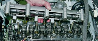
- An amazing picture appeared before us.
- 1 – fuse that prevents the circuit from jumping.
- 2 – fastening the timing chain tensioner shoe.
- 3 – crankshaft sprocket.
- We unscrew the fuse using a 10mm wrench and the tensioner fastening, as well as the bolt securing the auxiliary drive sprocket (pig).
We remove all the sprockets and the old chain. We check the matches of the marks. The crankshaft key should be opposite the ebb on the cylinder block.
We install new sprockets on the crankshaft and the drive of auxiliary units. Lubricate the new timing chain and install it in place.
- We place any tool under the chain on top so that it does not fall down.
We install the camshaft sprocket in the chain in such a way that when installed on the camshaft, the descending branch of the chain is tensioned and all marks coincide.
We turn the camshaft counterclockwise at a small angle and return it back by the crankshaft, this way the chain is tensioned and you can evaluate the correct installation of the marks.
If the marks do not match, transfer the chain to the tooth and repeat the procedure again.
We install the chain tensioner in place and activate it. Tighten all the sprocket mounting bolts and lock them. We turn the crankshaft two turns and if the valves do not meet the pistons and all the marks fall into place, we congratulate ourselves on completing the most important operation.
Lubricate the crankshaft cover gasket with sealant and install it in place.
We install the pulley, tighten it and turn the crankshaft again and check all the marks. It’s better to play it safe than to tear your hair out all over the place and look for the mechanic’s phone number.
We unscrew the nut 13 of the distributor and, having taken it out, turn the slider so that it faces the contact of the fourth cylinder. We put the distributor in place, but remember that after final assembly we will have to turn on the ignition. We will not dwell on this, since this procedure can easily be found on the Internet. If you are interested, there is a video about installing the ignition at the end of the article.
We put back everything that was removed, in the reverse order of removal. Fill with antifreeze, start, adjust the ignition. Your first timing chain replacement has come to an end.
Valve lid
The valve cover protects the gas distribution mechanism from external influences and also prevents oil leaks. The valve cover gasket is designed to seal the joint between the valve cover and the cylinder head. It is a strip of rubber whose shape exactly follows the contours of the valve cover.
Replacing the valve cover gasket
If there are oil leaks from under the valve cover, the gasket should be replaced. To do this, you need to remove the valve cover (you already know how to do this from the section on valve adjustment) and the gasket. The new gasket is installed without any special tools or equipment.
The valve cover gasket is placed on the surface of the cylinder head by hand, without any tools.
The installation site must be thoroughly cleaned of remnants of the old gasket and traces of sealant. We put the new gasket in place and install the valve cover on the engine.
Valve cover tightening procedure
After installing the valve cover on the engine, it must be secured with nuts to the cylinder head. To prevent distortion, displacement and damage to the gasket, there is a special procedure for tightening the nuts. The essence of this process is to tighten the fasteners from the center to the edges.
- Tighten the central nut.
- Tighten the second central nut.
- Tighten the outer nuts on one side of the cover.
- Tighten the outer nuts on the opposite side of the cover.
- Tighten the nut on the valve cover protrusion.
The valve cover nuts must be tightened in a specific order to avoid distortion and deformation of the gasket.
By following the order in which the nuts are tightened, you are guaranteed to avoid subsequent problems with oil leakage from under the valve cover.
Troubleshooting the VAZ 2107 timing shaft
When the camshaft is removed from the “bed”, it is necessary to assess its condition. First this is done visually. The camshaft must be replaced if its working surfaces (cams and bearing journals) have:
- scratches;
- bullies;
- cut wear (for cams);
- enveloping a layer of aluminum from the “bed” (for support necks).
In addition, the camshaft must be replaced if even the slightest traces of deformation are found.
The degree of wear of the support journals and the supports themselves is determined using a micrometer and caliper. The table below shows the permissible diameters of the journals and working surfaces of the supports.
Defect detection is carried out using a micrometer and calipers
Table: permissible diameters of the camshaft journals and its “bed” supports for VZ 2107
| Serial number of the neck (support), starting from the front | Allowable dimensions, mm | |
| Minimum | Maximum | |
| Support journals | ||
| 1 | 45,91 | 45,93 |
| 2 | 45,61 | 45,63 |
| 3 | 45,31 | 45,33 |
| 4 | 45,01 | 45,03 |
| 5 | 43,41 | 43,43 |
| Supports | ||
| 1 | 46,00 | 46,02 |
| 2 | 45,70 | 45,72 |
| 3 | 45,40 | 45,42 |
| 4 | 45,10 | 45,12 |
| 5 | 43,50 | 43,52 |
If during the inspection it is determined that the dimensions of the working surfaces of the parts do not correspond to those given, the camshaft or “bed” must be replaced.
Tightening torque for cylinder head of VAZ 2107
It's no secret that a well-repaired cylinder head is the key to stable, uninterrupted operation of the engine with maximum power output and normal fuel consumption, therefore repair of the VAZ cylinder head should be carried out with special attention, since any mistake can lead to damage to almost all engine parts and new expensive repairs
Replacing the gasket
So, to do this job, we will need:
A 10 wrench, preferably a head with a wrench or ratchet A 13, 17 and 19 socket head Flat and Phillips screwdrivers Extensions Wrenches and ratchet handles A torque wrench is the main tool that is required to perform this job
Step-by-step guide with photos on replacing the head gasket
I’ll say right away that the photographs presented in this article show the process of completely removing the carburetor, intake and exhaust manifold. But in fact, you can do without removing all these nodes. You can completely dismantle the cylinder head with the carburetor and manifolds installed on it.
So, first read the instructions for removing the camshaft on a VAZ 2107. After that, unscrew the coolant supply pipes:
And after that we take it aside:
Also, do not forget to disconnect the wires from the oil pressure sensor:
We check that all hoses and pipes are disconnected so that nothing is damaged when removing the cylinder head. Then you can unscrew the bolts securing the head to the cylinder block, first we tear them off with a wrench, and then you can twist them with a ratchet to make things go faster:
After all the bolts are completely unscrewed, you can carefully lift the cylinder head:
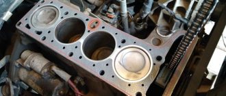
And finally we remove it from the block, the result of which can be seen in the photo below:
Carefully inspect the surface of the head from the inside to understand why the gasket burned out and antifreeze passed between the joint (if such symptoms were present on your car). If there are traces of corrosion close to the channels, then this is not allowed and it is advisable to replace such a cylinder head. If the traces of corrosion are not very deep, then you can grind the surface of the head to even out the grooves over the entire area. Of course, after such a procedure it will be necessary to select a thicker gasket in order to maintain the compression ratio.
If everything is fine with the cylinder head and you just need to replace the gasket, then be sure to thoroughly clean its surface. I do this with a special spray for removing gaskets, which is applied for 10-15 minutes and then cleaned off with a brush.
After this, carefully wipe the surface dry, install a new gasket on the block so that it lies exactly along the guides and you can install the cylinder head. Next, you need to tighten the bolts in a strictly defined sequence:
It is also worth noting that this should only be done with a torque wrench. I personally use an Ombra ratchet. It is suitable for most work on domestic cars, and the torque varies in the range from 10 to 110 Nm.
Removing the cylinder head
- Remove the battery. This will provide convenient access to the GBS head and protect against short circuits.
- Remove the air filter.
- Remove the carburetor on the carburetor version of the engine.
- Remove the ignition wires and distributor (if equipped).
- Drain the coolant from the cylinder head by unscrewing the plug. Before draining, you need to wait until the engine has cooled down.
- Loosen the clamps and disconnect the rubber pipes of the cooling system going to the cylinder head.
- Remove the valve cover by unscrewing the 8 nuts and removing them along with the shaped pressure washers.
- Loosen the chain tensioner by unscrewing the fixing nut. For convenience, you can completely dismantle it.
- Using a screwdriver and hammer, bend the edges of the lock washer on the camshaft gear mounting bolt and unscrew the bolt. Remove the gear. Tie the chain removed from the gear with wire so that it does not fall into the engine sump.
- Unscrew the camshaft mounting nuts (10 pieces) and remove it.
- Unscrew the brass nuts securing the exhaust pipe to the exhaust manifold and remove it along with the gasket.
- Using a powerful wrench, unscrew the 10 bolts that tighten the cylinder head and the eleventh bolt installed on the head casting. Remove the head. It is quite heavy, so in order not to scratch the car, it is better to remove it from the block together.
Video about replacing the cylinder head on a VAZ
Camshaft installation
The shaft installation process occurs in the reverse order using the same tools as for its removal. Additionally, you will need a torque wrench that can be used to control the tightening force. The work is carried out as follows:
- Before installing the part into the body, lubricate the support journals, bearings and cams with clean engine oil.
- We mount the product into the housing and tighten the fastening of the thrust plate.
- Checking the rotation of the shaft. It should rotate easily around its axis.
- We mount the housing together with the shaft on the studs in the cylinder head and tighten it in a certain sequence with a force of 18.3–22.6 Nm.
- We perform final assembly after marking.
Installation by marks
Upon completion of the replacement, it is necessary to align the camshaft and crankshaft to the marks. Only after such a procedure will the ignition timing be correct and engine operation stable. An additional tool you will need is a wrench to rotate the crankshaft, and the work itself consists of the following steps:
- We put the RV sprocket in place and tighten it, but not completely.
- We tighten the chain. To do this, unscrew the tensioner nut, turn the crankshaft a little, and then tighten the nut back.
- We turn the crankshaft with a wrench until the mark on the pulley is positioned opposite the length of the mark on the timing cover.
- The mark on the RV star should coincide with the ebb on the body. If this does not happen, unscrew the bolt, remove the gear and shift the chain by one tooth in the required direction.
- We install and clamp the gear with a bolt, check that the marks on both shafts match. We fix the bolt with a special washer.
- We adjust the thermal clearance of the valves.
- We install the valve cover, tightening it in a certain order.
- We install the remaining elements in their places.
When reinstalling the valve cover, I always pay attention to the condition of the gasket, even if it has recently been changed. There should be no tears, strong pressing or other damage on it.
In addition, the seal should not be “oak”, but elastic. If the condition of the gasket leaves much to be desired, I always replace it with a new one, thereby eliminating possible oil leakage in the future.
Adjustment of valves
It is recommended to adjust the valves on the “classic” every 30 thousand km. mileage or after engine repair. Tools you need to prepare:
- open-end wrench for 13 and 17;
- probe 0.15 mm.
To adjust the thermal clearances of the valves, use a special probe
The work is carried out on a cooled engine after removing the valve covers and tensioning the chain:
- We combine the crankshaft and camshaft marks with the marks, which corresponds to the top dead center of the fourth cylinder.
- We check the clearance of valves 6 and 8. To do this, insert a feeler gauge between the cam PB and the rocker. If it fits in without effort, the gap needs to be made smaller. If it fits tight, then more.
- To adjust, loosen the lock nut with a 17 mm wrench, and use a 13 mm wrench to set the required gap, after which we tighten the lock nut.
- We adjust the remaining valves in the same way, but in a certain order, for which we turn the crankshaft.
Table: procedure for adjusting cylinder head valves on a “classic”
| Crankshaft rotation angle, o | Camshaft rotation angle, o | Cylinder numbers | Adjustable valve numbers |
| 4 and 3 | 8 and 6 | ||
| 180 | 90 | 2 and 4 | 4 and 7 |
| 360 | 180 | 1 and 2 | 1 and 3 |
| 540 | 270 | 3 and 1 | 5 and 2 |
Video: adjusting valves on a VAZ 2101–07
Some car enthusiasts use a narrow feeler gauge from the kit to set valve clearances. I would not recommend using it for the procedure in question, since if the valve lever is skewed, and the rockers can be skewed even with normal springs and good condition of the valve, a narrow feeler gauge will not allow for precise adjustment. And it’s more convenient to set the gap with a wide feeler gauge.
If there is no special feeler gauge for adjusting the valves, you can use a narrow feeler gauge from the kit
Replacing the camshaft on a VAZ 2106 does not require the owner to have high qualifications or special tools. Repairs can be carried out in a garage with a regular car set of keys and screwdrivers. If you follow the step-by-step instructions, the procedure will take about 2-3 hours, after which the gas distribution mechanism of your car will work clearly and smoothly.
Also check out
- Using a key set to “13”, unscrew the nine nuts from the camshaft “bed”.
- Remove the camshaft from the studs, dismantle it along with the “stock”.
- Unscrew the mounting bolts of the thrust flange with a 10mm wrench and remove the flange.
- Lift the cam, thereby releasing the spring pressure, and remove it.
- Remove the camshaft from the “bed”.
- Remove the cam spring.
Reassemble in reverse order. , the replacement of the camshaft of the VAZ 2107, VAZ 2106 can be considered complete
Note!
The camshaft stock mounting nuts should be tightened in strict accordance with the diagram below.
Nivsky camshaft for engine 2106 1.6 L
Post by tatarin545 » Jan 13, 2011, 00:21
I think all owners of VAZ-2121 with 1.6 liter engines will be interested in the issue of installing a Niva camshaft (213) on the 2106 engine. I remember not long ago an acquaintance on a VAZ-2107 installed a Niva camshaft on the sixth engine (1.6), which he boasted about, saying it goes faster.
I would like to know. 1. Will there be an increase in engine power (dynamics, traction, consumption, etc.). 2. Does the springs require replacement? 3. No one has worked magic with this camshaft on a split gear; there are positive results.
It would be a good alternative (budget) instead of a low camshaft.
(until I save up at the grassroots)
Who installed it, share your experience.
Tatar is not a nationality, Tatar is a profession.
I am slowly looking for an engine block or the 2130 engine itself. 42-tooth RK gear, inexpensive! Niva Fora for experiments, can be written off!
Re: Niva camshaft for engine 2106 1.6 L
Post by Captain » Jan 13, 2011, 07:19
Re: Niva camshaft for engine 2106 1.6 L
Post by tatarin545 » Jan 13, 2011, 7:34 pm
Tatar is not a nationality, Tatar is a profession.
I am slowly looking for an engine block or the 2130 engine itself. 42-tooth RK gear, inexpensive! Niva Fora for experiments, can be written off!
Re: Niva camshaft for engine 2106 1.6 L
Post by MNV » Jan 13, 2011, 10:18 pm
Re: Niva camshaft for engine 2106 1.6 L
Post by Captain » 14 Jan 2011, 06:58
2106 engine block or other block upgrades.
Post by tatarin545 » Jan 24, 2011, 9:26 pm
I decided to start a new topic without getting into the boring of the 1.6 + or - block.
Today I spoke with a mechanic I know, a man with golden hands who can fix anything that moves and has a motor and much more. I talked about grinding the intake manifolds, to which he said that it was all bullshit and that he tried what I found out on the internet with a wrench and a caliper in his hands. He told me what he did with his block. So he has a 2101 car, a 1.6 block which is bored out to 1.7, i.e. for 82 pistons from 2108, a Niva crankshaft is installed, which differs from 2106 only in balancers and the piston strokes are the same, the block on top where the cylinder head lies is shortened by 2 mm, i.e. The combustion chamber has been reduced and the compression ratio has been increased. In our neighboring city, a private owner uses a machine to remove metal for only 500 rubles. He doesn’t know about the block overheating. His kopek 160 goes easily and just presses the gas and says it’s vomiting from under his ass. It runs on 92 gasoline, but it says 95 better because of the compression ratio, which is calculated at 95 or 98, but nothing says 92, too. It's been going like this for 2 years. The motor does not heat up because the liner is thinner and there is a possibility of the liner breaking due to pressure. he doesn't know.
So what will he give us for our Nivas? 1. Shortening the block by 1 mm or 2 mm (increasing the compression ratio). 2. Installation of Nivsky KShM for blocks 2106.
It will be good or bad. How will it work with a low-level camshaft or simply with a Nivsky camshaft on 2106! And off-road driving calculations!
Or other ways to improve the engine block! Share!
Tatar is not a nationality, Tatar is a profession.
I am slowly looking for an engine block or the 2130 engine itself. 42-tooth RK gear, inexpensive! Niva Fora for experiments, can be written off!
Malfunctions of the VAZ 2107 camshaft, their symptoms and causes
Considering that the timing shaft is subject to constant dynamic and temperature loads, it cannot last forever. It is difficult even for a specialist to determine that this particular unit has failed without detailed diagnostics and troubleshooting. There may be only two signs of its malfunction: a decrease in power and a quiet knocking sound, which manifests itself mainly under load.
The main camshaft faults include:
- wear of the working bodies of the cams;
- wear of the surfaces of the bearing journals;
- deformation of the entire part;
- shaft fracture.
Wear of cams and journals
Wear is a natural occurrence for a constantly rotating part, but in some cases it can be excessive and premature. This leads to:
- insufficient oil pressure in the system, as a result of which lubricant does not flow to loaded areas or is supplied in smaller quantities;
- low-quality motor oil or one that does not meet established requirements;
- defect in the production of the shaft or its “bed”.
If the cams wear out, the engine power is noticeably reduced, since they, being worn out, cannot provide either the appropriate phase width or the required lift of the intake valve.
When the cams wear out, engine power drops
Deformation
Camshaft deformation occurs as a result of severe overheating caused by malfunctions of the lubrication or cooling systems. At the initial stage, this malfunction may manifest itself in the form of a characteristic knocking sound. If you suspect such a breakdown, further operation of the car is not recommended, as it can damage the entire gas distribution mechanism of the engine.
Deformation occurs due to malfunctions in the lubrication and cooling systems
Fracture
A camshaft fracture may be a consequence of its deformation, as well as poor timing. In the event of this malfunction, engine operation stops. In parallel with this problem, others arise: destruction of the shaft “bed”, bending of valves, guides, damage to parts of the piston group.
A shaft fracture may be a consequence of deformation
What bearings to put
When a wheel bearing requires replacement, the question immediately arises of which part to install. Many people advise using original components. However, today the quality of parts leaves much to be desired and the issue of choice remains quite relevant.
Table: type, installation location, and size of bearings
| Installation location | Bearing type | Size, mm | Quantity |
| Front wheel hub (outer support) | Roller, conical, single row | 19,5*45,3*15,5 | 2 |
| Front wheel hub (inner support) | Roller, conical, single row | 26*57,2*17,5 | 2 |
| Rear axle shaft | Ball, radial, single row | 30*72*19 | 2 |
Manufacturer's choice
When choosing a manufacturer of a wheel bearing for a VAZ “Seven”, we can recommend SKF, SNR, FAG, NTN, Koyo, INA, NSK. The companies listed have many locations around the world. These products are of high quality and meet the most stringent requirements.
Among the domestic manufacturers that supply bearings for cars of the Togliatti plant, we can highlight:
- CJSC "LADA Image" - manufactures and sells original Lada wheel bearings through secondary markets;
- Saratov plant - produces parts under the SPZ brand;
- Volzhsky Plant - uses the Volzhsky Standard brand;
- Vologda plant - sells products under the VBF brand;
- Samara plant SPZ-9.
Bolts in VAZ family cars
Fasteners are presented in a wide range, they have different sizes and purposes. For example, the rear door shock absorber mounting bolt 2108-09 or the roof support mounting bolt. If you are repairing a generator, you will also need the appropriate fastener. Even to fix a ball license plate, certain hardware is needed.
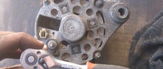
The photo shows the cylinder head bolts of a VAZ 2108.
Bolts for alloy wheels
VAZ wheel bolts are designed for fixing alloy wheels, the total length is 51 mm. Approximate cost of elements:
- a VAZ M 12×30.5 wheel bolt costs from 35 rubles;
- secret bolts for VAZ-2101-12 set – 280 rubles;
- wheel hardware M12×1, 25×28 zinc from 45 RUR/piece;
- The eccentric bolt on the VAZ (shown in the photo) allows you to install any wheels with a 4×100 drill bit.
Wheel bolts on VAZ for alloy wheels have a thread length of 28, 30 and 33 millimeters. Standard factory fasteners come with dimensions of 12×1.25 with a total length of 44 mm and a thread length of 24 mm.
Transmission mounting bolt
M12×45 brand fasteners are suitable as standard parts for transmissions and gearboxes on VAZ 2101, 2102, 2103, 2104, 2105, 2106, 2107 models. For VAZ gearboxes, M 12×1.24 Belebey fasteners are used.
Arm bolts
A broken beam bolt (rear suspension arm) is usually discovered when trying to perform wheel alignment. The result is a discovered lever that is not properly secured. On VAZ cars, there are no problems replacing the upper arm, since the fasteners are clearly visible and easy to reach. Bend the pressing petal and knock out the 14x243 element. You will have to work longer with the rear fasteners, since you have to remove the hardware through the lower hole in the beam. It is recommended to use a screwdriver or tweezers as tools.
Using available tools, install new bolts. When replacing, do not dismantle the lower arm. When one hardware is unscrewed and removed, the second one must be fully tightened. This will allow fastening without distortion of the lower axis. It is recommended to have a jack on hand, which should be placed under the lower arm mount and at the same time adjust its position. This technique will lighten the load on the bolt and simplify installation.
Camber bolts
With frequent use of the vehicle, the camber bolts stretch, resulting in a change in the alignment angle of the front wheels. In this case, the problem with stuck fasteners is detected on alignment/camber when the thread breaks. Car owners often ask the question: why change the camber bolts? The M12×1.25 hardware has a fine thread. Due to corrosion processes and repeated unscrewing, the thread profile wears out. With each subsequent installation, the risk of stripping the thread increases. It is recommended to replace the kit to avoid unpleasant situations with broken threads during camber.
Coolant drain bolt
To drain the coolant from the engine compartment, unscrew the special drain bolt. It is located on the left side. The tools you will need are a 13mm wrench.
Video text
OEMZIP – search for spare parts and accessories for cars. More details: https://oemzip.ru/
Read the description. Subscribe to the channel. Give it a thumbs up.
In this video we will talk about how to stretch the head onto a VAZ 2101-2107. Pulling torque and order.
R214713400725 (rubles) Z199072463730 (usd)
My bitcoin address is: 1Pqccuf6CqezY7aeh4JFzp9bvvqewtLnnN
VAZ 2107 car engine
Crankshaft main bearing cap bolts Oil pan mounting bolts Breather cover mounting stud Breather cover mounting nut Cylinder head mounting bolts
Cylinder head bolt
Intake manifold and exhaust manifold mounting nuts Connecting rod cover bolt nuts Flywheel mounting bolts Chain tensioner shoe mounting bolt Nuts of the camshaft bearing housing studs Mounting camshaft sprocket bolts Oil pump drive shaft sprocket mounting bolt Valve adjusting bolt nut Valve adjusting bolt sleeve Spark plug Bolt coolant pump fastenings Nut stud fastening the outlet pipe of the cooling jacket Crankshaft ratchet Bolt fastening the generator bracket Nut fastening the mounting plate of the generator Bolt nut fastening the generator to the bracket Nut fastening the mounting bar to the generator Nut fastening the cushion to the front support bracket Nut fastening the front engine mount cushion to the cross member Nut securing the plate to the cushion Nut securing the rear engine mount to the body Nut securing the rear support to the gearbox Nut of the bolt securing the rear support to the cross member Electric fan sensor
M8 M9x1 M10x1.25 Ml 0x1.25 M8 Ml 0x1.25 Ml 0x1.25 Ml 2x1.25 M18xl.5 Ml 4x1.25 M8 M8 M20xl.5 Ml 0x1.25 M10xl.25 M12x1.25 M10x1, 25 Ml 0x1.25 M10xl.25 M6 M8 M8 M8 M22x1.5
VAZ 2107 car clutch
Bolts securing the clutch housing to the engine Bolts securing the clutch basket to the flywheel Nut of the clutch pedal bolt Nuts securing the clutch master cylinder Clutch hydraulic tube connections
VAZ 2107 gearbox
Reversing light switch Nuts connecting the clutch housings and gearboxes Nuts connecting the clutch housings and gearboxes Bolts securing the rod clamp cover Nuts securing the rear cover Nut securing the elastic coupling flange to the secondary shaft Intermediate shaft bearing clamp washer bolt Bolts securing the forks to the rods
M14x1.5 M10x1.25 M8 M8 M8 M20x1 Ml 2x1.25 M6
cardan transmission of the car VAZ 2107
Nut of the front propeller shaft fork Nuts of the bolts securing the elastic coupling Nuts of the bolts securing the propeller shaft flange to the gearbox flange
M16x1.5 M12x1.25 M8
rear axle of a VAZ 2107
Gearbox mounting bolts Differential bearing cover mounting bolts Driven gear mounting bolts Nut securing the flange to the driving gear
Nut for the mounting plate of the axle shaft bearing and brake shield
M8x1.25 M10x1.25 M10x1.25 M16x1.5
front suspension of a VAZ 2107 car
Bolt securing the cross member to the body spar Nuts of the lower bolts securing the cross member to the body spar Nut of the bolt securing the lower arm axle Nut of the lower arm axle Nut of the upper arm axle Nut securing the upper end of the shock absorber Nut securing the lower end of the shock absorber Nut of the front wheel hub bearings
Nuts for attaching the stabilizer bar to the steering knuckles. Nuts for attaching the ball pins to the steering knuckles. Bolts for securing the wheels. Nuts for the steering knuckle bolts.
M12x1.25 M12x1.25 M12x1.25 M14x1.5 M14x1.5 M10x1.25 M10x1.25 M18x1.5
M8 M14x1.5 M12x1.25 M10x1.25
rear suspension of the car VAZ 2107
Nuts for fastening shock absorbers Nuts for fastening bolts of transverse and longitudinal rods
steering wheel of a VAZ 2107 car
Nut of the steering housing mounting bolt Nut of the mounting bolt of the pendulum arm bracket Nuts of the ball pins of the steering linkages Bolt of fastening the intermediate shaft to the upper shaft and to the worm shaft Steering wheel mounting nut Nuts of fastening the steering shaft bracket Nut of fastening the bipod Swinging arm axle nut