MY MOTORCYCLE
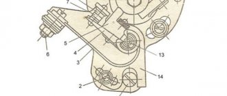
A correctly adjusted Ural or Dnepr should start with half a turn. If, despite the carburetor float chambers being filled with gasoline, you have to hit the kickstarter for a long time before the engine reluctantly starts to spark, then it’s time to adjust the ignition. This must also be done if the engine backfires when starting, and knocks during operation, overheats, or runs poorly, let’s turn our attention to the classic system with a PM 302A breaker, which is equipped with the vast majority of heavy motorcycles. Let's look at the whole process from the very beginning.
On a new motorcycle (if you were lucky enough to buy one), the contacts, as a rule, are skewed and touch at one point. Using small pliers, you need to slightly bend the contact fastenings so that the area of their contact is maximized. It is more convenient to bend the movable contact hammer; it is more pliable.
After this, the contacts should be cleaned with sandpaper, folding it in half and placing it between the contacts. You don't need to remove a lot of metal. Then the sandpaper should be replaced with a soft cloth soaked in clean gasoline, and the remaining abrasive should be thoroughly removed. After completing this operation, it will not be superfluous to lubricate the axis of the moving contact by dropping 1-2 drops of spindle or motor oil onto it. Apply a few drops of the same oil to the felt felt.
Let's install the breaker with the ignition timing machine in place (don't forget about the mark on the machine's leash!). Now let's adjust the gap between the contacts. Let's set the cam to the position where they are maximally open. Having loosened the screw securing the fixed contact, we will rotate the eccentric with a screwdriver, while simultaneously measuring the gap size with a 0.5 mm thick feeler gauge. When the probe begins to enter the gap with slight friction, carefully close the screw.
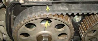
Turning the crankshaft using the kickstarter, we will find an arrow on the flywheel (for “Urals”) or a “TDC” mark (for “Dneprs”) and set it opposite the mark in the viewing window.
Now you need to turn on the ignition. Let's take an 8x10 wrench and apply it to the steel core of the coil. We will turn the breaker body in the direction of the arrow stamped on its cover until the key touches the core. In this position, lightly tighten the breaker mounting screws so that it can rotate, but with some effort.
Let's take a long thin rod, for example, an old knitting needle, rest one end of it against the breaker flange, and apply light blows to the second with a small hammer or a 19x22 wrench, thereby slowly turning the breaker in the opposite direction. At the moment the contacts open, the key, attracted to the ignition coil, will fall with a melodious ringing. In this position, the breaker mounting screws must be tightened.
It remains to check that the initial ignition timing we have set is correct. To do this, turn the crankshaft until the contacts close, hang the key on the reel again and, turning the crankshaft with light blows of your fist on the kickstarter, slowly bring the arrow on the flywheel closer to the mark on the crankcase. If the key falls when they match, everything was done correctly. If the arrow does not reach the mark, the ignition is early, and the breaker body needs to be turned slightly in the direction of the arrow on its cover. If the key falls after the marks coincide, turn the breaker in the opposite direction.
At first glance, the amount of work seems quite large. But in everyday use, all operations are not required, and besides, by adjusting the ignition once or twice, you will learn to do this in a matter of minutes, and this system will no longer cause you trouble.
source
How to adjust the ignition on a boxer
A correctly adjusted Ural or Dnepr should start with half a turn. If, despite the carburetor float chambers being filled with gasoline, you have to hit the kickstarter for a long time before the engine reluctantly starts to spark, then it’s time to adjust the ignition. This must also be done if the engine backfires when starting, and knocks during operation, overheats, or runs poorly, let’s turn our attention to the classic system with a PM 302A breaker, which is equipped with the vast majority of heavy motorcycles. Let's look at the whole process from the very beginning.
On a new motorcycle (if you were lucky enough to buy one), the contacts, as a rule, are skewed and touch at one point. Using small pliers, you need to slightly bend the contact fastenings so that the area of their contact is maximized. It is more convenient to bend the movable contact hammer; it is more pliable.
After this, the contacts should be cleaned with sandpaper, folding it in half and placing it between the contacts. You don't need to remove a lot of metal. Then the sandpaper should be replaced with a soft cloth soaked in clean gasoline, and the remaining abrasive should be thoroughly removed. After completing this operation, it will not be superfluous to lubricate the axis of the moving contact by dropping 1-2 drops of spindle or motor oil onto it. Apply a few drops of the same oil to the felt felt.
Let's install the breaker with the ignition timing machine in place (don't forget about the mark on the machine's leash!). Now let's adjust the gap between the contacts. Let's set the cam to the position where they are maximally open. Having loosened the screw securing the fixed contact, we will rotate the eccentric with a screwdriver, while simultaneously measuring the gap size with a 0.5 mm thick feeler gauge. When the probe begins to enter the gap with slight friction, carefully close the screw.
Turning the crankshaft using the kickstarter, we will find an arrow on the flywheel (for “Urals”) or a “TDC” mark (for “Dneprs”) and set it opposite the mark in the viewing window.
Now you need to turn on the ignition. Let's take an 8x10 wrench and apply it to the steel core of the coil. We will turn the breaker body in the direction of the arrow stamped on its cover until the key touches the core. In this position, lightly tighten the breaker mounting screws so that it can rotate, but with some effort.
Let's take a long thin rod, for example, an old knitting needle, rest one end of it against the breaker flange, and apply light blows to the second with a small hammer or a 19x22 wrench, thereby slowly turning the breaker in the opposite direction. At the moment the contacts open, the key, attracted to the ignition coil, will fall with a melodious ringing. In this position, the breaker mounting screws must be tightened.
It remains to check that the initial ignition timing we have set is correct. To do this, turn the crankshaft until the contacts close, hang the key on the reel again and, turning the crankshaft with light blows of your fist on the kickstarter, slowly bring the arrow on the flywheel closer to the mark on the crankcase. If the key falls when they match, everything was done correctly. If the arrow does not reach the mark, the ignition is early, and the breaker body needs to be turned slightly in the direction of the arrow on its cover. If the key falls after the marks coincide, turn the breaker in the opposite direction.
At first glance, the amount of work seems quite large. But in everyday use, all operations are not required, and besides, by adjusting the ignition once or twice, you will learn to do this in a matter of minutes, and this system will no longer cause you trouble.
Troubleshooting problems with the ignition system on a Ural motorcycle
Checking the ignition system, first of all, occurs with an initial check of the functionality of the breaker. It is important to pay attention to the operation of the incendiary advance machine , in which various complaints are undesirable. The resistance of the primary winding, which is measured by the tester, must be at least 6 ohms. Next, the secondary winding is checked, for which the tester is connected to the high voltage connections. The voltage of such a winding should be exactly 10 kOhm.
Repair of Ural and Dnepr motorcycles , like many others, cannot be done without all these manipulations aimed at optimizing its operation.
Checking the ignition does not end there. Next, the spark plug caps and high voltage wires ring. Resistance indicators, in these cases, should vary. The plug caps should have approximately 2 kOhm, and the wires should have almost zero (this is an important aspect). During these manipulations, the problem will be found and eliminated.
Contactless ignition system for motorcycle Ural, Dnepr
Solving the problem of the reliability of the ignition system on my Ural motorcycle, I came to the conclusion that it was necessary to install a BSZ...
Having considered the huge abundance of options for contactless ignition systems, both on the market and on the Internet, I decided to make for myself the simplest option for the electronic part. Namely, use a Zhiguli Hall sensor and switch. The reason for choosing this particular combination was that I like to travel far and for a long time, and you must admit that if a specific unit specifically for a motorcycle fails along the way, it is not always possible to find a replacement for Saurman or an opto sensor somewhere in the outback, just as it is not always possible to carry it with you contact ignition kit in reserve. And spare parts for Zhiguli can be found in any village.
Search for BSZ kit
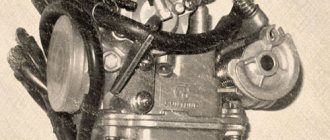
So, the choice has been made, all that remains is to implement it. I went to the market. I bought a switch for a VAZ 2108, a Hall sensor and a piece of wiring from a VAZ 2107 distributor. I bought a two-terminal coil from Oka. I also needed an old breaker housing to make a mounting panel for the Hall sensor that I had.
How to make a butterfly for BSZ
The simplest, but not the most correct option was to make a modulator butterfly, ordering it from a turner, which could be rigidly fixed to the shaft. In this case, the ignition timing would remain constant all the time. Of course, it would be possible to add an additional FUOZ unit (ignition timing generator) to this option, but, based on my concept of “reliability in simplicity,” this option also did not suit me. I wanted the engine to work as it should, without complicating the electronic part, so I went to the market again and bought a new Ural cam with a centrifugal regulator. I approached the selection of the cam responsibly and bought the most reliable one, not a Chinese one.
We make a plate for the hall sensor
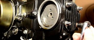
I took the old body from the breaker, removed all the insides from it, and sawed off the vertical walls to a horizontal plane. The result is a plate like this.
Next, having thought about how to secure the Hall sensor, I decided to “sink” it and secure it at the bottom of the plate, fortunately there was 3 mm of free space under the plate, just right for attaching the sensor. This mounting option seemed to me the most rigid, plus the sensor mounting screws will not be unscrewed due to engine vibrations, since they will rest against the housing. I made the necessary cut in the plate along the width of the sensor, drilled two holes and cut an M3 thread. I installed the Hall sensor on the plate and secured it with M3 screws with countersunk heads.
We manufacture a modulator for BSZ
I measured the vertical distance from the slot in the sensor to the edge of the plate. I got distances from the bottom edge of the sensor slot of 6 mm from the top of 10 mm. I installed the plate on the motorcycle, installed the cam with the centrifugal regulator in place, looked at how the lower edge of the cam sits in relation to the plate, it should be approximately at the same level. I transferred the distance from the plate to the center of the slot in the sensor to the cam body. In my case it turned out to be 8 mm. Marked a horizontal line. The curtains will be welded at this level. I left the marking line for release.
I measured the distance from the center of the shaft on which the cam sits to the Hall sensor housing through the slot - 28-29mm. I decided that the diameter of the butterfly should be 54 mm, so that there would be a gap of 2 mm between the edge of the curtain and the sensor body. Somewhere on the BSZ discussion forums I read that for the switch to work properly, a 2/1 cycle is required. That is, two parts of the sector are closed, one part is open. It turns out 120 degrees metal, 60 degrees slot.
Determined the central axis of the cam. If you look at the cam directly in the center of the hole, you will see that the cam is not round. Only two parts are round, and two seem to have been ground off. The axis passes through the centers of both rounded parts, i.e. where the contacts remain open. Using simple calculations, I marked four vertical lines on the cam. Got clear boundaries of sectors horizontally and vertically.
I ordered a mandrel from a turner - a round metal washer 8 mm thick, 54 mm in diameter and with an internal hole of 22 mm, so that the round part of the cam would fit tightly into the washer, without play. The sectors for the modulator were first cut out of cardboard. I did this with the metal: I cut out a round piece from a 1 mm sheet of iron with a chisel, and drilled a hole in the center for an M8 bolt. I drove a bolt into this hole, tightened it with a nut, inserted it into the drill, turned on the drill and carefully sanded the edges of the workpiece with a file to the desired diameter and shape.
I marked the resulting workpiece into 4 sectors, two at 120 degrees and two at 60 degrees. I carefully sawed one marked side into two halves, put both parts together, and made a cut along the remaining line. Got the required sectors. Next, holding the sectors again in a vice, I made it as on a paper blank, and drank the required shape under the welding site.
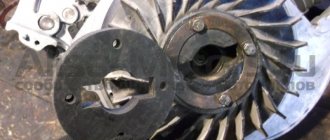
After all these manipulations I went to the welder. Well, everything is simple there. We inserted the cam into the mandrel turned by a lathe. We laid the petals on the mandrel, oriented them along the marked lines and welded them to the eccentric. The most difficult part of the BSZ butterfly modulator was ready.
Installing BSZ on a motorcycle
Installation on the motorcycle did not take long. The old ignition had already been removed. In its place I installed a plate with a Hall sensor and put the butterfly modulator in place.
I determined the places where the switch will be located (in my case, near the battery) and the ignition coil (under the front of the tank).
I used silicone wires from the coil to the spark plugs with automobile rubber tips (more than once they helped me out in heavy rain). I ran the wiring to the switch from the Hall sensor, having first lengthened it a little.
I connected the plus of the switch and the ignition coil to the standard wiring wire, which used to go to the breaker, and the minus of the switch to the housing, using the switch mounting bolt. The negative wire of the coil was connected to terminal No. 1 of the switch, as indicated in the diagram. He turned on the ignition and cranked the engine. There was a spark. All that was left was to turn on the ignition.
We set the ignition for the first time with the BSZ butterfly modulator.
We set the ignition almost as described in the manual, but with some adjustments due to the fact that we now have no contacts. The opening moment is determined by the spark on the spark plug when the modulator curtain passes through the Hall sensor.
So. We set the crankshaft to mark P (early ignition, first mark, complete alignment of the arrow on the crankshaft and the marks in the center of the window). We unscrew the spark plug from the left cylinder, put on a high-voltage wire, and provide the spark plug with reliable ground. We move the weights as far as they will go and by turning the body of the plate with the Hall sensor we catch the moment of the spark. Having caught the position of the plate at which the spark jumps, we tighten it with three screws. We check again to make sure that the angle is not knocked down when tightening. The spark should jump at the moment of maximum divergence of the weights. The next step is to check the advance angle on the second cylinder. We rotate the crankshaft 360 degrees (a full turn) until the marks and marks P coincide. And we check for the presence of a spark at the point where the weights are completely separated. (We do not touch the plate with the Hall sensor) If a spark appears at the moment of complete divergence, then you can congratulate you, everything was done correctly.
We bring the modulator to mind.
If, when checking the second cylinder, a spark appeared before the weights reached their maximum or did not appear at all, then the modulator was made out of alignment. In this case, the spark will be in the cylinders at different ignition timing angles. This defect can be removed quite simply as follows.
Let's first figure out why the spark didn't appear. But it did not appear for the reason that the modulator curtain did not open completely and did not go all the way. You just need to help it open, file its edge a little with a file (the one that is located in the slot of the Hall sensor). In order not to confuse the edges of the modulator, we mark the edge that “does not spark” with a felt-tip pen or in some other way and then file it down until a spark appears. (Four strokes of the file were enough for me and a spark appeared).
Now let’s look at the option of a spark appearing until the weights are maximally separated. The curtain opens before the weights reach their maximum spread. It is necessary to reset the ignition on this side of the modulator. We do not touch the crankshaft; it is already installed in the desired position, mark P in the center of the window for the desired cylinder. We unscrew the three screws of the plate with the Hall sensor, move the weights to the maximum and catch the moment of the spark. Got caught? Great. We tighten the plate, check the spark at the maximum spread of the weights. Now turn the crankshaft a full turn until mark P appears in the window for the next cylinder. In this position of the crankshaft we again try to get a spark. It shouldn't exist. We mark this edge of the modulator with a felt-tip pen and work it with a needle file until a spark appears. Now your modulator has been adjusted and the ignition is set to 80 gasoline.
How to set the ignition on a Ural motorcycle for 92 gasoline
If you use the 92nd, then you need to adjust the ignition a little, do it a little earlier. Set the crankshaft to the position where the P mark has just appeared in the window, under the upper edge of the window. In this position, install the ignition.
I’ll add that this season, with this ignition option, my motorcycle has covered about 8,000 kilometers. The weather conditions were very varied from +3⁰ at night to +45⁰ in the heat in the steppes. More than once I had to drive in heavy, prolonged downpours. There was not the slightest malfunction in the ignition system.
Editorial staff of the online magazine “My Automobile.South”
This might be interesting
- On bicycles through the mountains This is a report on a journey by bicycles through the Caucasus Mountains of completely unprepared people. Read this article and you...
- Car loan. Article 5. Reviews about car loans It’s up to you to decide whether to take out a car loan or not. We publish reviews from consumers and car owners who at one time...
- Tuning the Izh motorcycle. BSZ on Izh Jupiter The main “soreness” of the Izh Jupiter motorcycle engine is the standard contact ignition system. Any owner of Jupiter...