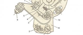
Spark torque sensor location:
1
– spark torque sensor
2
– vacuum regulator
3
– hatch plug in the clutch housing
4
– engine auxiliary drive housing
| You will need | |
| |
Before starting work
Remove the air filter.
The ignition timing is checked and set at engine idle (at a crankshaft speed of 820–900 rpm). The angle should be within 1°± 1° BTDC.
If the ignition timing is incorrectly set, the engine overheats, does not develop full power, and detonation occurs.
Marks for checking the ignition timing
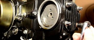
| Check the ignition timing using the mark on the flywheel and the scale of the crankshaft rear oil seal holder (the rubber plug has been removed). When the marks on the flywheel are combined with the middle division (notch) on the scale, the piston of the first cylinder is installed at TDC. One division on the scale corresponds to 2° of crankshaft rotation. | |
| The ignition timing can also be checked and set using the marks on the generator drive pulley and the front camshaft drive belt cover. The long mark corresponds to the installation of the first cylinder at TDC, the short mark to the ignition advance by 5° of crankshaft rotation. These marks are used to set the ignition timing on the stand. |
| EXECUTION ORDER |
| 1. Disconnect the hose from the vacuum regulator. 2. To check the ignition timing, connect the “+” terminal of the strobe to the “+” terminal of the battery, a. 3. . The ground clamp of the strobe light is connected to the “–” terminal of the battery. 4. Remove the tip of the high-voltage wire from the spark plug of the first cylinder and connect it to the strobe sensor in accordance with the instructions included with the strobe. 5. Remove the rubber plug from the clutch housing hatch. 6. Start the engine and direct the flashing strobe light into the clutch housing hatch. 7. When the ignition timing is correctly set, mark 8. To set the ignition timing, loosen the three nuts securing the spark timing sensor. 9. To increase the ignition timing angle, turn the sensor housing clockwise (the “+” mark on the flange of the sensor housing is towards the protrusion on the auxiliary drive housing. In this case, one division on the flange corresponds to 8° of crankshaft rotation). 10. To reduce the ignition timing angle, turn the sensor housing counterclockwise (the “-” mark on the sensor housing flange to the protrusion on the auxiliary drive housing). Tighten the sensor mounting nuts, check and, if necessary, repeat the ignition timing setting. Connect the hose to the vacuum regulator. Good day! Some time ago I noticed that my Oka periodically shoots at the silencer. At the same time, I have never heard detonation on it, except very briefly when starting off very sharply. I noticed that the distributor was turned 1 division counterclockwise relative to its average position (i.e., 8 degrees along the crankshaft, as they say in the book). I turned the distributor approximately 1/4 notch clockwise (that is, I set it to 2 degrees earlier). It became noticeably easier to move away (it became almost as easy as driving a UAZ truck - the car stopped either stalling or jerking sharply), and it seemed like the traction at the bottom increased. and the engine stopped firing from the muffler. Maybe try to tighten it up some more? I heard that on engines 2108/09 (and therefore on Oka, probably) detonation is not as audible as on other engines (Volga, UAZ, Lada, etc.). And in the instructions they write (unlike the UAZ) to adjust not by detonation, but by strobe (which I don’t have, of course). How to set the ignition correctly on Oka? Thanks for any answers! Setting the ignition “by ear” We set the sensor firmly to “+”, not paying attention to any risks and so on. We find a flat section of the road, accelerate on it to 60-65 km/h (if the jerker is 1111 - up to 55-60 km/h), stick the fourth gas pedal firmly to the floor. Engine detonation will be clearly audible with a characteristic metallic tinkling sound (they still ignorantly say that “fingers are knocking”). We stop, turn the sensor a little to minus, and repeat the ride. The goal is to ensure that when the pedal is pressed to the floor, the detonation knock is practically one or two “dings” and immediately stops. I drove with this setup for several years and didn’t know any grief. not having an ear for music by the way Teapot In 1989, car enthusiasts saw the first copies of the VAZ 1111, which became the basis for the family. Three factories mastered the production of small cars: VAZ in Togliatti, KamAZ in Naberezhnye Chelny, Serpukhov, whose car plant specialized in the production of motorized wheelchairs for the disabled. This distribution of forces and resources made it possible to quickly begin production of this model without the construction of new production facilities. Buyers were offered two versions of the car, which differed only in the power unit. The car has front-wheel drive, and replacing the Oka timing belt is carried out by analogy with VAZ 2108 and VAZ 21083 engines. |
About the engine
For these models, engines 2108 and 21083 were taken as the basis. They are 2-cylinder engines with an in-line vertical arrangement of cylinders. The camshaft is installed in the cylinder head. The working volume is 649 cm 3 and 749 cm 3. The increase in volume is obtained by increasing the diameter of the pistons from 76 mm to 82 mm. The cylinder blocks of these engines, heads, flywheels, and pulleys are different.
Many spare parts are unified with their 4-cylinder variants. The power supply system is carburetor, but with changed calibration data. In 1990, the timing belt on the power unit was replaced. If the previous product had semicircular teeth, then on the new one they began to have a trapezoidal shape with a groove at the top of the tooth. The pulleys were changed to match the tooth profile, but the belts themselves are interchangeable; you can use both new and old parts.
It is possible to obtain maximum efficiency from using an internal combustion engine only with the correct adjustment of the valve timing. There are marks on the timing drive for this purpose. One of them is the protrusion on the rear cover for the drive belt protection, which should coincide with the mark on the camshaft pulley. The second mark is located at the bottom of the cylinder block, and it coincides with the mark on the crankshaft pulley. The piston of the first cylinder should be at top dead center at this time.
Are the valves bending?
This question worries many owners, since after such an “incident” a costly overhaul of the power unit will follow. Mechanics know of cases where, after the pistons met the valves, in addition to bent valves, the piston heads were damaged and the guide bushings in the cylinder head were destroyed. The engine, based on the VAZ 21083 engine, is free from such shortcomings. The pistons of this internal combustion engine have recesses that prevent the valve head from meeting the upward-moving piston.
This problem can occur in two cases:
- Cutting teeth on the timing belt.
- The alignment marks on the engine being repaired are not aligned correctly.
To avoid this, you should carefully study the process of replacing the belt, or seek help from service center specialists.
Oka gas distribution mechanism
If you compare old VAZ classic engines with a timing chain drive, you will notice significant differences in the design of the drive. The bulky metal chain was replaced with a timing belt. The design of the cylinder block has become shorter and lighter, since the opening for the chain in the timing drive mechanism has disappeared. The designers changed the principle of opening valves, it became simpler. If on old engines the camshaft cam pressed on the valve stem through the rocker arm, now it acts on it through the adjusting washer. The thermal gap is set on a cold engine by selecting a washer of the required thickness. Manufacturers make them in different sizes, the values of which are marked on the ends of the washer. If the driver adjusts the thermal gap independently, he will have to purchase a certain number of such washers, which is not always economically feasible.
The design of the timing mechanism drive is such that the belt drives the pump in the Oka engine cooling system. Often it is because of the breakdown of this pump that the toothed belt drive fails. Therefore, car manufacturers recommend that the belt drive and pump in the engine cooling system be replaced at the same time. When inspecting, you should pay attention to the condition of the tension roller in the timing mechanism.
Belt replacement procedure
The process of replacing a timing belt on Oka is not very difficult. If you carefully study the process before doing this, you can do it yourself. The work can be done on any level surface.
Before starting the operation, install wheel chocks under the rear wheels and tighten the hand brake cable. The front wheels are turned to the right as far as possible (all the way), and the battery is disconnected. The further procedure will be something like this:
- In the engine compartment, remove the spare wheel and the windshield washer fluid reservoir. You will also have to dismantle the air filter housing and ignition coil.
- After loosening the tension on the generator set drive belt, remove it from the pulleys.
- After this, you can remove the protective plastic timing case.
- Next, rotate the crankshaft clockwise until all the timing marks in the timing drive are aligned.
- It is not yet possible to remove the toothed belt; the generator set drive pulley on the engine crankshaft is in the way. There is a hole on the right mudguard in the direction of travel of the car. A 19mm socket wrench is inserted into it to unscrew the bolt on the crankshaft pulley. Before doing this, you should secure the motor from turning. This can be done through a hole in the top of the flywheel housing by inserting a strong screwdriver or suitable pry bar between the flywheel teeth. An assistant should hold it.
- Unscrew the bolt securing the generator pulley and remove it from the shaft.
- Next, loosen the tension of the timing belt. To do this, you need a 17mm wrench to loosen the tension roller nut. If it is replaced, then completely remove it from the axle. There is an adjusting washer in front of the roller on the block side.
- If the pump in the engine cooling system is being replaced, drain the antifreeze and then remove it from the engine block.
- Remove the toothed belt. Important! The engine cannot be cranked after this, so as not to bend the valves.
- Carefully inspect the condition of the timing drive pulleys, clean them of possible contamination and traces of engine oil.
- Installing a new timing belt is done in the reverse order. Before this, carefully check once again how the timing marks in the timing drive mechanism match. At the end of the work, manually turn the engine several times, and again check how the marks match.
OKA car gas distribution mechanism
Maximum engine efficiency can be achieved only by correctly adjusting the valve timing. This is largely facilitated by the timing marks marked on the drive. The first of them, in the form of a protrusion, is located on the cover of the drive belt protective cover. It should coincide completely with the one located on the crankshaft pulley. The second mark is located at the bottom of the cylinder block and must also coincide with the mark on the crankshaft. When setting the marks, the cylinder piston must be at the top point (TDC).
If you compare old VAZ model engines that have a chain timing drive, which is bulky and noisy, it is not difficult to notice very significant differences. The bulky chain is replaced by a timing belt. The design of the block has changed a lot; it has become shorter and lighter. The opening of the valves has also changed, the principle has become simpler.
Structurally, the drive is designed so that it operates a pump that pumps engine coolant. Often, due to damage to the pump, the belt breaks, so designers recommend that when changing the timing belt, if possible, also replace the cooling system pump. This will avoid many further problems. You also need to inspect the tension roller; you may have to change it too.
Replacement timing
The vehicle operation regulations recommend that owners check the condition of the belt drive and belt tension after a run of 30 thousand km (more often). It is recommended to replace it after 60 thousand km. If the car owner does not change the belt within this period, it may be destroyed.
It is not allowed to operate the Oka with traces of engine oil leaks in the area where the toothed belt operates. It has a bad effect on the belt material and accelerates its destruction. Engine oil leaks should be repaired and the toothed belt replaced with a new spare part. If you carry out maintenance work on the power unit in a timely manner and with high quality, then there will be no problems for the owner.
To ensure normal engine starting in any weather, a huge number of different devices and parts are used. However, they are combined into one system - ignition (I). You will learn more about SZ for the Oka car below. What functions does the Oka ignition coil perform, what malfunctions are typical for SZ as a result, and how to set the advance angle - read below.
Well before we talk about how to set and adjust the ignition on the Oka at home in accordance with the diagram, it is necessary to understand the features of the SZ.
The ignition system on any car means several different components, the main ones being:
- Spark timing controller. This device is equipped with vacuum and centrifugal regulators. The device is designed to ensure the moment of spark formation, taking into account its standard setting, the number of engine revolutions, and the load on the engine. The signal reading procedure is based on the Hall effect.
- A switching device is designed to open the supply circuit of the primary winding of a short circuit, thus converting control signals into current pulses. When the ignition is activated, the connector of the switching device cannot be disconnected under any circumstances, as this will lead to damage not only to this unit, but also to other parts of the SZ.
- Coil. In the ignition systems of Oka cars, in accordance with the circuit, a two-terminal short circuit with an open or closed magnetic circuit is used.
- Candles. This commonly heard element is designed to transmit a high-voltage pulse, which promotes the ignition of the flammable mixture in the cylinders of the internal combustion engine. The service life of spark plugs is about 10,000 km; alas, the myth figure changes enormously according to the specificity of the spark plugs themselves. Or to the minimum, if for some reason the service life of the spark plugs is reduced.
- High-voltage cables designed to connect spark plugs to a distributor. In Oka, high-voltage circuits with distributed resistance are used. You should not touch them while the engine is running, as this can be a prerequisite for serious injury. It is also prohibited to start the unit if the high-voltage circuit is broken (the wires may be broken or crumpled, their insulation may be damaged). If the insulation is broken, then, of course, other elements of the accounting system will fail in accordance with the diagram.
- Egnition lock. In accordance with the diagram, the lock is designed to start the engine by supplying voltage to an additional relay when the key is turned (video creator - Nail Poroshin).
How to set the ignition on Oka
A huge number of different devices and parts are used to ensure normal engine starting in any weather. However, they are combined into one system. ignition (SZ). You will learn more about SZ for Oka car below. What are the functions of the Oka ignition coil, what malfunctions are inherent in SZ as a result, and how to set the advance angle. see below.
Before you start talking about how to install and adjust the ignition on the eye of the house in accordance with the diagram, you need to understand the features of the SZ.
The ignition system on any car means several different components, the main ones being:
- Spark torque regulator. This device is equipped with vacuum and centrifugal controllers. The device is designed to set the moment of spark formation, taking into account its standard setting, the number of engine revolutions, and the load on the engine. The signal reading procedure is based on the Hall effect.
- The switching device is designed to open the power supply circuit of the primary winding of the short circuit, thereby converting control signals into current pulses. With the ignition on, the switching device switch cannot be turned off under any circumstances, as this can damage not only this unit, but also other parts of the SZ.
- Coil. Oka ignition systems use a two-contact, open or closed magnetic circuit in accordance with the diagram.
- Spark Plugs This common ear element is designed to transmit a high voltage pulse that helps ignite the flammable mixture in the cylinders of an internal combustion engine. The service life of spark plugs is about 10,000 km, unfortunately, the myth changes in a huge direction in accordance with the specifics of the spark plugs themselves. Or, at least, if for some reason the service life of the spark plugs is reduced.
- The high-voltage cable is designed to connect the spark plugs to the distributor. Oka uses high voltage with distributed resistance. Do not touch them while the engine is running as this may result in serious injury. It is also forbidden to start the device if the high voltage circuit is broken (the wires will be interrupted in another way, and they may like damaged insulation). If the insulation is broken, then, of course, other elements of the metering system will not work in the circuit.
- Ignition lock. According to the diagram, the lock is designed to start the engine by applying voltage to an additional relay when the key is turned (video creator: Nail Powder).
READ How to Correctly Set the Ignition on a Cherry Amulet
Early ignition of the eye VAZ1111
Among the disadvantages of SZ, the following should be highlighted:
- Coil damage. This problem is rare, but it does occur occasionally.
- Damage to the distributor. You can find more information about distributor defects, and besides troubleshooting, you can read here without any problems.
- Worn spark plugs or carbon deposits. This is a problem for most of our fellow citizens. Read about why there is soot and what ways to eliminate this problem here.
- Malfunction of high-voltage wires. The wires are broken (broken), in other words they will look more like broken insulation. Operating a vehicle with this problem is not allowed.
- Ignition failure Due to wear on the inside of the lock, the driver will not be able to start the engine using the existing key. The problem can be solved by changing the lock cylinder (video creator: Misha Burashnikov).
How to set the correct angle:
- First you need to open the hood and remove the air filter. The angle diagnostic procedure is performed with the engine idling, so the crankshaft should be running at about 850-900 rpm. Angle a itself can deviate from TDC by no more than one degree. In this case, if it is installed incorrectly, sometimes the engine overheats and the machine does not have time to fully develop the required power. Getting out of the car causes detonation problems.
- To prevent the ignition angle from leading to such effects, you must first align the mark on the ICE flywheel with the normal mark on the scale. The first mark is located on the flywheel itself, the second. on the crankshaft oil seal scale. At this point, the piston in the cylinder will be positioned at TDC. When installing, keep in mind that each division corresponds to two stages of crankshaft clamping.
- In addition, the ignition procedure for parameters A can be performed taking into account the marks located on the generator drive pulley on the timing belt cover. The greatest risk should be setting the piston of cylinder 1 to the TDC position. In terms of short-term danger, this corresponds to a 5-degree crank advance.
- Disconnect the pipe connected to the vacuum regulator. Having done this, you can disconnect the high voltage cable from the plug installed in cylinder 1. This normal hearing aid will then need to be connected to the bus. Before use, read the operating instructions for the device.
- Follow these steps to remove the rubber plug from the clutch housing. The light flux is simultaneously directed into the crankcase. Then, if the angle is set correctly, the risk will be between 2 and 3.
- Next, use a wrench to remove the three nuts that secure the spark sensor. If you want to increase the torque, then the controller must be turned clockwise, respectively, if you decrease it, then counterclockwise. Once the adjustment is complete, the nuts will need to be tightened.
READ How to Correctly Set the Ignition on Niva 2121
VAZ 11113. Installation of 40 belt teeth.
For more information on how to replace the ignition coil in Oka in makeshift conditions, watch the video below (creator: Butovo channel Kutil).
Source
Early ignition of the eye VAZ1111
Among the defects of SZ, the following should be highlighted:
- Coil failure. Such a discrepancy rarely happens, however, it does happen sometimes.
- Distributor failure. You can easily read more about distributor defects and additional troubleshooting here.
- Spark plugs are worn out or carbon deposits appear there. This problem is of great concern to the majority of our fellow citizens. Read about the reasons why carbon deposits occur and what methods are available to eliminate this problem.
- Malfunction of high-voltage wires. Wires can be broken (broken), in other words, you will like them better if the insulation is broken. Operating a vehicle with such a discrepancy is not allowed.
- Broken ignition switch. Wear of the inside of the lock will result in the driver being unable to start the engine with the existing key. The problem can be solved by changing the lock cylinder (the creator of the video is Misha Burashnikov).
Operation of the Oka car ignition system and possible problems with it
To ensure normal engine starting in any weather, many different mechanisms and elements are used. But they are all combined into one system - the ignition system (I). We will tell you more about the SZ for the Oka car below. What functions does the Oka ignition coil perform, what malfunctions are typical for SZ in general, and how to set the advance angle - read below.
Contactless SZ scheme on Oka
Before we talk about how to set and adjust the ignition on the Oka with your own hands in accordance with the diagram, let's understand the features of the SZ.
The ignition system on any car includes several different components, the main ones:
- Spark timing controller. This device is equipped with vacuum and centrifugal regulators. The device is designed to ensure the timing of spark formation, taking into account its standard installation, the number of engine revolutions, and the load on the motor. The signal reading procedure is based on the Hall effect.
- The switching device is designed to open the supply circuit of the primary winding of the short circuit, thus converting control signals into current pulses. When the ignition is activated, the connector of the switching device must not be disconnected under any circumstances, since this will lead to damage not only to this unit, but also to other elements of the SZ.
- Coil. In the ignition systems of Oka cars, in accordance with the diagram, a two-terminal short circuit with an open or closed magnetic circuit is used.
- Candles. This element is designed to transmit a high-voltage pulse, which contributes to the ignition of the combustible mixture in the cylinders of the internal combustion engine. The service life of spark plugs is about 10 thousand km, but this figure can be changed upward in accordance with the specifics of the spark plugs themselves. Or to a lesser extent, if for some reason the service life of the spark plugs is reduced.
- High-voltage cables designed to connect spark plugs to a distributor. In Oka, high-voltage circuits with distributed resistance are used. Do not touch them while the engine is running, as this may cause serious injury. It is also prohibited to start the power unit if the high-voltage circuit is broken (the wires may be broken or crushed, or the insulation on them may be damaged). If the insulation is broken, then other elements of the system may fail in accordance with the diagram.
- Egnition lock. According to the diagram, the lock is designed to start the engine by supplying voltage to an additional relay when the key is turned (video author - Nail Poroshin).
Typical system malfunctions
Among the malfunctions of the SZ, the following should be highlighted:
- Coil failure. This problem doesn't happen often, but it can happen nonetheless.
- Distributor failure. You can read more about distributor malfunctions, as well as troubleshooting, here.
- Spark plugs are worn out or have carbon deposits on them. This problem is relevant for many of our compatriots. Read about the reasons why soot appears and what ways to eliminate this problem exist in this article.
- Malfunction of high-voltage wires. The wires may be broken (broken) or their insulation may be damaged. Operating a car with such a problem is not allowed.
- Broken ignition switch. Wear on the inside of the lock will result in the driver being unable to start the engine with the existing key. Replacing the lock cylinder will solve the problem (the author of the video is Mikhail Burashnikov).
Ignition installation instructions
How to set the lead angle correctly:
- First of all, you need to open the hood and remove the air filter. The angle diagnostic procedure should be carried out at idle engine speed, while the crankshaft should operate at a frequency of about 850-900 rpm. The angle itself can be deviated from TDC by no more than one degree. If it is set incorrectly, the motor may overheat, and the machine as a whole will not be able to develop the required power. Depending on the car, the problem may also cause detonation.
- To prevent the set ignition angle from leading to such consequences, you first need to align the mark on the flywheel of the internal combustion engine with the middle mark on the scale. The first mark is located on the flywheel itself, the second is on the scale of the crankshaft rear oil seal. At this moment, the piston in the cylinder will be located at TDC. When setting, keep in mind that each division corresponds to two degrees of the crankshaft gate.
- In addition, the ignition adjustment procedure can be carried out taking into account the marks located on the generator drive pulley and on the timing belt protective cover. The longest mark should correspond to the installation of the piston of cylinder 1 in the TDC position. As for the short mark, it corresponds to a five-degree advance of the crankshaft rotation.
- You need to disconnect the pipe connected to the vacuum regulator. Having done this, you can disconnect the high-voltage cable from the spark plug installed in cylinder 1. This wire will subsequently need to be connected to the strobe - before use, read the service book of the device.
- After completing these steps, you need to remove the rubberized plug from the clutch housing hatch. The luminous flux should be directed into the crankcase hatch itself. If the angle is set correctly, the mark will be between marks 2 and 3.
- Next, using a wrench, you need to loosen the three nuts that secure the spark sensor. If you need to increase the torque, then the controller should be turned clockwise, respectively, if you decrease it, then counterclockwise. When the adjustment is complete, the nuts will need to be tightened.
Photo gallery
Video “Instructions for replacing the ignition coil”
Learn more about how to replace the ignition coil in Oka with your own hands from the video below (author - Butovsky Gulyak channel).
Design
The ignition system of the VAZ Oka consists of only seven main elements:
- Auxiliary relay;
- Egnition lock;
- Circuit breakers;
- Switch;
- Spark moment sensor;
- Coil;
- Candles;
All elements are connected to each other by wiring.
Using the ignition switch, the driver controls the power supply to the system from a source - the battery, while the voltage passes through the auxiliary relay and fuses. The lock has three positions - “0”, in which all electrical consumers are turned off, “1” - voltage is supplied to the ignition system and a number of other devices, and “2” - current is supplied to the starter. This switching sequence ensures that the ignition system is activated at the moment the engine starts.
How it all works
The principle of operation of the ignition system is as follows: after turning the key to position “1” el. Energy from the battery is supplied to the ignition system components through the lock, fuses and auxiliary relay. In this case, high voltage pulses are not generated, since the spark torque sensor is not yet operational.
After activating the starter, the timing drive begins to rotate the camshaft, and accordingly the sensor shaft - the Hall sensor begins to interact with the screen, due to which control pulses are created.
Arriving at the commutator, these pulses interrupt the power supply circuit of the coil winding. When the power circuit is broken, a high voltage pulse is induced in the coil, which is transmitted through high-voltage wires to the spark plug, which leads to the formation of a spark between its electrodes.
Malfunctions
The simplified design of the ignition system and the absence of moving components ensures high reliability and ease of maintenance.
There are not so many malfunctions in the Oka ignition system:
- Switch failure;
- Hall sensor malfunction;
- Coil failure;
- Breakage or breakdown of wires, oxidation of contacts;
- Spark plug malfunction;
- Violation of the ignition timing;
Since the ignition system is directly involved in the operation of the engine, any malfunction in it immediately affects the performance of the engine - interruptions occur, the unit does not develop power, popping noises appear, or the unit simply does not start.
Diagnosis of a malfunction is carried out by visual inspection of the wiring and its connections, as well as by sequentially replacing all components with known good ones. A check using measuring instruments allows you to more accurately determine the faulty element.
The search for the problematic element is carried out from the candles. That is, first the presence of a spark is checked on them, then the high-voltage wires are inspected, and then the performance of the coil, switch, and Hall sensor is diagnosed.
The components of the ignition system are non-repairable, so if they break down they must be replaced.
Setting the advance angle
Setting the ignition timing is the only operation that is performed in the ignition system.
A strobe light is used to set the angle correctly. The technology for performing the work is not complicated. The algorithm of actions is as follows:
- We connect the strobe to the power source and the tip of the spark plug of the 1st cylinder (according to the instructions for the device);
- Remove the plug from the inspection window on the clutch housing;
- We start the engine (it should be idling);
- We direct the beam of light from the strobe into the viewing window;
- We determine the position of the marks (with the angle correctly set, the mark on the flywheel at the moment the strobe light beam flashes should be located between the central and rear marks on the crankcase);
- If the marks are not positioned correctly, make adjustments. To do this, loosen the bolts securing the spark moment sensor and rotating it around its axis until the marks match;
After adjustment, tighten the sensor fasteners, turn off the engine, disconnect the strobe light and replace the plug.
VAZ 1111 | Setting the ignition timing | Oka
Service and operation
Manuals → VAZ → 1111 (Oka)
Spark torque sensor location:
1 – spark torque sensor 2 – vacuum regulator 3 – hatch plug in the clutch housing 4 – engine auxiliary drive housing
| You will need |
|
Before starting work
Remove the air filter.
The ignition timing is checked and set at engine idle (at a crankshaft speed of 820–900 rpm). The angle should be within 1°± 1° BTDC.
If the ignition timing is incorrectly set, the engine overheats, does not develop full power, and detonation occurs.
| Check the ignition timing using the mark on the flywheel and the scale of the crankshaft rear oil seal holder (the rubber plug has been removed). When the marks on the flywheel are combined with the middle division (notch) on the scale, the piston of the first cylinder is installed at TDC. One division on the scale corresponds to 2° of crankshaft rotation. |
| The ignition timing can also be checked and set using the marks on the generator drive pulley and the front camshaft drive belt cover. The long mark corresponds to the installation of the first cylinder at TDC, the short mark to the ignition advance by 5° of crankshaft rotation. These marks are used to set the ignition timing on the stand. |
| EXECUTION ORDER |
1. Disconnect the hose from the vacuum regulator.
2. To check the ignition timing, connect the “+” terminal of the strobe to the “+” terminal of the battery, a.
3. . The ground clamp of the strobe light is connected to the “–” terminal of the battery.
4. Remove the tip of the high-voltage wire from the spark plug of the first cylinder and connect it to the strobe sensor in accordance with the instructions included with the strobe.
5. Remove the rubber plug from the clutch housing hatch.
6. Start the engine and direct the flashing strobe light into the clutch housing hatch.
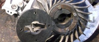
7. When the ignition timing is correctly set, mark 1 on the flywheel should be between the middle division 2 and the previous division 3 of the scale. Otherwise, it is necessary to adjust the ignition timing.
8. To set the ignition timing, loosen the three nuts securing the spark timing sensor.
9. To increase the ignition timing angle, turn the sensor housing clockwise (the “+” mark on the flange of the sensor housing is towards the protrusion on the auxiliary drive housing. In this case, one division on the flange corresponds to 8° of crankshaft rotation).
10. To reduce the ignition timing angle, turn the sensor housing counterclockwise (the “-” mark on the sensor housing flange to the protrusion on the auxiliary drive housing). Tighten the sensor mounting nuts, check and, if necessary, repeat the ignition timing setting. Connect the hose to the vacuum regulator.
Spark torque sensor location:
1
– spark torque sensor
2
– vacuum regulator
3
– hatch plug in the clutch housing
4
– engine auxiliary drive housing
| You will need | |
| |
Before starting work
Remove the air filter.
The ignition timing is checked and set at engine idle (at a crankshaft speed of 820–900 rpm). The angle should be within 1°± 1° BTDC.
If the ignition timing is incorrectly set, the engine overheats, does not develop full power, and detonation occurs.
OKA ignition system
How to set the ignition on Oka
If Oka's car does not start the first time, then you need to set the ignition correctly. Also, the proper functioning of the ignition affects fuel consumption and the overall dynamics of the vehicle.
Sponsored by PG Articles on the topic How to set the ignition on the Oka How to correctly adjust the carburetor How to change spark plugs on a Skoda Octavia How to connect beepers
First, remove the air filter. You only need to check the ignition timing when the engine is idling. The crankshaft rotation speed should be 820–900 rpm. The advance angle should not deviate more than 1° from top dead center.
Other announcements on the topic:
The ignition system is one of the main systems of a car. If the ignition is set incorrectly, the engine will begin to overheat, will not develop full power, fuel consumption will increase significantly, and detonation will appear. To check the ignition timing, you can
Read
Correct setting of the ignition timing in a contactless ignition system makes it possible to operate the car in comfortable conditions. Otherwise, the engine does not develop full power and fuel consumption increases. You can set the contactless ignition not only to 100, but
The normal operation of a car engine depends on the correct ignition timing. Otherwise, fuel consumption increases, the vehicle's thrust decreases, and pistons, connecting rods and piston pins are destroyed. You should inspect its installation from time to time in order to always be
Mad" Auto mechanic - setting up the ignition and mixture Oka 11113
Troit Oka
.
Setting the ignition on the Oka
.
Oka
carburetor .
We set the timing marks
In this video
I'll tell you in detail how to
set
the timing marks on
the eye
. If anyone wants to help develop the channel, here's a qiwi.
The operation of a car engine is impossible without correctly set ignition timing. This is noticeable not only when starting it with the starter, but also when driving. Increased discomfort is created from uneven operation, a drop in engine power, increased fuel consumption and, most importantly, the car
The car's ignition system is one of the main ones. Without it, there is no way to start the engine and start driving. In addition, incorrectly set ignition timing not only causes discomfort when driving a car, but also contributes to increased fuel consumption, and in some cases
Read
Adjustment of the contactless ignition system on UAZ vehicles must be carried out with high precision. Mistakes made when installing the ignition lead to an increase in fuel consumption and a decrease in engine power. Sponsor of PG placement Articles on the topic How to adjust the ignition on a UAZ How
Ignition problems quite often occur on VAZ cars. That is why experienced motorists have developed several methods with which you can quickly and easily adjust the ignition of a VAZ. Since adjustment can take a long time, quite often it is only done
Perhaps, one of the ways to most accurately determine for yourself the correctness of the ignition timing set in a car engine is to determine the specified parameter using a strobe light, which is always available for sale in any store that sells vehicles.
The ignition timing in a car is determined by the angle of rotation of the crankshaft from the moment the spark appears at the spark plug to the position of the piston at top dead center. The ignition angle is lost due to a poorly tensioned chain or a twisted belt. For good engine operation it is necessary to set the angle
For reliable operation of the Buran snowmobile engine in difficult operating conditions, it is necessary to correctly adjust the ignition system. The most important parameter that has to be taken into account when adjusting is the ignition timing setting. As a rule, even the factory setting
Repair of VAZ 1111 (Oka): Setting the ignition timing
Spark torque sensor location:
1 – spark torque sensor 2 – vacuum regulator 3 – hatch plug in the clutch housing 4 – engine auxiliary drive housing
| You will need |
|
The ignition timing is checked and set at engine idle (at a crankshaft speed of 820–900 rpm). The angle should be within 1°± 1° BTDC.
If the ignition timing is incorrectly set, the engine overheats, does not develop full power, and detonation occurs.
| Check the ignition timing using the mark on the flywheel and the scale of the crankshaft rear oil seal holder (the rubber plug has been removed). When the marks on the flywheel are combined with the middle division (notch) on the scale, the piston of the first cylinder is installed at TDC. One division on the scale corresponds to 2° of crankshaft rotation. | |
| The ignition timing can also be checked and set using the marks on the generator drive pulley and the front camshaft drive belt cover. The long mark corresponds to the installation of the first cylinder at TDC, the short mark to the ignition advance by 5° of crankshaft rotation. These marks are used to set the ignition timing on the stand. |