February 27, 2015 Lada.Online 312 280 23
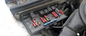
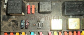
The relay and fuse box is also called the mounting block or black box. If problems are identified in the car related to electrical equipment, first check the fuses and relays. If they burn out, we replace them with the same ones, but first we must determine the cause of the burnout. The article contains a complete description of all Lada Largus mounting blocks.
Fuses and their tasks
Protection of circuits through elements allows timely prevention of failure of expensive electrical components and equipment.
Probably, no one likes to stop in the middle of the highway with a faulty pantograph that does not allow further movement. Here the role of fusible links can hardly be overestimated. Fuses are small plates with two contacts connected by a fusible working element. The main purpose of this product is to protect circuits from the risk of short circuits that damage the electrical equipment of the network. Also, a non-working element may not prevent a fire. The closure process itself initiates the burnout of the fuse element inside the element housing, as a result of which the equipment is de-energized. In this case, it is necessary to find the causes of the problems, eliminate them and replace the fuse-link that has become unusable. The cost of these products is insignificant, so we recommend that you always keep a whole set of fuses on hand. It has different inserts configured for different network loads.
For each pantograph separately, the manufacturer used an individual fuse with its own power settings. When replacing a failed insert, it is necessary to replace it with an analogue one with an identical load rating. Confusion here is unacceptable, since each element is designed for a certain current strength.
The inserts vary in color. The maximum current that the fuse can withstand is indicated on their body. If a failure of electrical equipment is noticed, the first thing you should do is check the condition of the fuses and relays. These components guard the normal operation of the entire vehicle network.
In Lada Largus, these elements are located in special mounting blocks, of which there are two. The first is located in the engine compartment close to the switching module. There are fuses responsible for the operation of important systems, namely:
- motor electrical equipment;
- ignition;
- electrical components of the cooling circuit;
- on-board controller, etc.
The second fuse box can be found inside the LADA Largus interior. The manufacturer placed it on the left side of the panel.
Fuse and relay box in the interior of Lada Largus
Most fuses are installed in the fuse mounting block located in the passenger compartment, at the left end of the instrument panel, under a plastic cover.
The table and figure show the maximum possible set of fuses. On a specific vehicle, depending on the configuration, some fuses may be missing.
| № | Strength top, A | Color | Protected target |
| F1 | 20 | Yellow | Windshield wiper, windshield wiper switch, heated tailgate relay |
| F2 | 5 | Beige | Instrument cluster, fuel pump relay, engine control unit (ECU) |
| F3 | 10 | Red | Brake light switch |
| F4 | 10 | Red | Diagnostic connector, immobilizer antenna unit, body electrical control unit |
| F5 | – | – | Reserve |
| F6 | – | – | Reserve |
| F7 | – | – | Reserve |
| F8 | – | – | Reserve |
| F9 | 10 | Red | Instrument cluster, left low beam |
| F10 | 10 | Red | Low beam right headlight |
| F11 | 10 | Red | Instrument cluster, left high beam |
| F12 | 10 | Red | High beam right headlight |
| F13 | 30 | Green | Rear door window motors |
| F14 | 30 | Green | Front door power window motors |
| F15 | 10 | Red | ABS electronic control unit, acceleration sensors, steering angle sensor |
| F16 | 15 | Blue | Electrically heated front seats |
| F17 | 15 | Blue | Sound signal |
| F18 | 10 | Red | Left front and rear parking lights |
| F19 F20 | 10 7,5 | Red Brown | Right front and rear parking lights, glove compartment lighting, instrument cluster lighting, hazard warning switch, HVAC control unit, audio system, cigarette lighter, central locking switch, front door power window switches, license plate lights, right lights front and rear position lights Rear fog light |
| F21 | 5 | Beige | Electrically heated exterior mirrors |
| F22 | – | Reserve | |
| F23 | – | – | Reserve |
| F24 | Reserve | ||
| F25 | – | Reserve | |
| F26 | 5 | Beige | SRS system |
| F27 | 20 | Yellow | Tailgate wiper motor, horn, TDC sensor, reverse light switch |
| F28 | 15 | Blue | Interior electrical control unit (energy saving mode) |
| F29 | 15 | Blue | Interior electrical control unit, diagnostic connector |
| F30 | 20 | Yellow | Interior electrical control unit |
| F31 | 15 | Blue | Fog lights, fog light relay |
| F32 | 30 | Green | Heated tailgate glass |
| F33 | – | Reserve | |
| F34 | – | Reserve | |
| F35 | – | Reserve | |
| F36 | 30 | Green | Electric motor for heating, air conditioning and ventilation systems |
| F37 | 5 | Beige | Electric exterior mirrors |
| F38 | 15 | Blue | Audio system, cigarette lighter |
| F39 | 10 | Red | HVAC Motor Relay |
Purpose of fuses in the block installed in the passenger compartment
The internal fuse block is equipped with elements responsible for the systems:
- 1 – windshield cleaning device, heated rear window;
- 2 – tidy, ECU control relay for fuel pump, navigation device;
- 3 – stop button;
- 4 – turn signals and power supply to the diagnostic block, control of the size relay, parking module;
- 5-8 – reserve cells;
- 9 – low beam of the left headlight, assistance in controlling the tidy, pump for the headlight cleaning system;
- 10 – is fully responsible for the low beam of the right headlight;
- 11 – far left side and tidy;
- 12 – far right;
- 13/14 – section of rear/front power windows;
- 15 – ABS device and steering wheel rotation and acceleration sensors;
- 16 – electric heating of the rear sofa;
- 17 – beep;
- 18 – side lights of the left side, illumination of license plates, glove compartment;
- 19 – dimensions on the right side of the car, illumination of license plates, glove box, emergency lights, acoustics, switches;
- 20 – rear fog lamp on the left side, and part of the dashboard;
- 21 – rear view mirror shades;
- 22 – navigation system terminal;
- 23 – empty;
- 24 – EUR;
- 25 – power supply to the gas installation;
- 26 – seat belt pretensioner device, airbag electronics;
- 27 – belt position indicator for driver, front passenger, rear window wiper, windshield washer pump control;
- 28 – acoustic module, instrument and interior lighting;
- 29 – diagnostic block, UCH;
- 30 – central locking;
- 31 – front fog lights;
- 32 – heated rear wind window and exterior mirrors;
- 33-35 – empty nests;
- 36 – stove and air conditioner;
- 37 – mirror control drive;
- 38 – cigarette lighter and speakers;
- 39 – depends on the configuration – is responsible for the stove, air conditioning, navigation system.
Heated rear window relay (interior)
Another important and often problematic device is the cabin relay for heating the stern door glass. The device is located in a niche behind the dashboard. To get there, you need to dismantle the panel and find the yellow cube on the red mount.
The module is removed from the socket quite simply and replaced with a similar one.
Relays and fuses Lada Largus (8 valves and 16 valves): block diagrams
Fuse and relay diagrams are suitable for modifications:
- Lada Largus R90
- Lada Largus F90
- Lada Largus cross
Volumes:
- Lada Largus 1.6 8 valves
- Lada Largus 1.6 16 valves
Year of release
| 2012 | 2013 | 2014 | 2015 | 2016 | 2017 | 2018 | 2019 | 2020 |
Where are the fuses and block located on the Lada Largus?
The fuse and relay box is scattered in two places.
Relay and fuse box under the hood
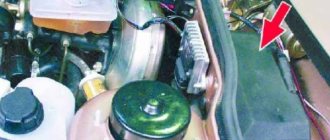
Some systems are protected by fuses located in the engine compartment in block B.
Fuse box in the passenger compartment
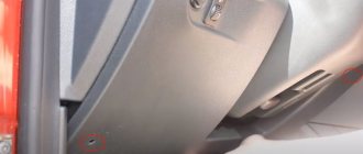
Located to the left of the steering column. Closed with a lid. To check the fuses, you need to disconnect cover A using recess 1 .
Relay and fuse diagram for Lada Largus under the hood
Relay Lada Largus mounting block under the hood (11189/21129)
| № | Denomination | Name |
| K2 | 20A | Gas system relay |
| K3 | 40A | Radiator Fan High Speed Relay |
| K4 | 20A | ECM main relay |
| K5 | 20A | Fuel pump relay |
| K6 | 20A | A/C compressor clutch relay |
| K7 | 20A | Low speed radiator fan relay |
| K9 | 20A | Fog light relay |
| K11 | 40A | Heater fan relay |
Fuse diagram of Lada Largus in the cabin from the left side
Lada Largus fuses in the cabin with descriptions
| № | Denomination | Protected circuit |
| F1 | 20A | Windshield wiper. Central body electronics unit (windshield wiper). Rear window heating relay control |
| F2 | 5A | Instrument cluster. Engine management system controller. Automotive terminal "ERA-GLONASS". Fuel pump relay control |
| F3 | 10A | Additional brake signal. Brake signal (rear lights). |
| F4 | 10A | Central body electronics unit (BCM). Diagnostic connector. Immobilizer antenna. Parking system control unit |
| F5 | Reserve | |
| F6 | Reserve | |
| F7 | Reserve | |
| F8 | Reserve | |
| F9 | 10A | Low beam (left headlight) |
| F10 | 10A | Low beam (right headlight) |
| F11 | 10A | High beam (left headlight) |
| F12 | 10A | High beam (right headlight) |
| F13 | 30A | Power windows for rear doors |
| F14 | 30A | Power windows for front doors |
| F15 | 10A | Anti-lock braking system control unit |
| F16 | 15A | Heated front seats |
| F17 | 15A | Main sound signal. Auxiliary sound signal |
| F18 | 10A | Side light (left headlight) . Side light (rear left light). License plate light. Glove compartment light |
| F19 | 10A | Side light (right headlight). Side light (rear right light). Illumination of switches and interior devices |
| F20 | 7.5A | Rear fog light (rear left light) |
| F21 | 5A | Heated exterior mirrors |
| F22 | 5A | Automotive terminal "ERA-GLONASS" |
| F23 | Reserve | |
| F24 | Reserve | |
| F25 | Reserve | |
| F26 | 5A | Airbag system control unit |
| F27 | 20A | Rear window cleaner. Window washer (rear/front). Reversing light (rear right light). Sound signal for unfastened driver's seat belt |
| F28 | 15A | Central body electronics unit (BCM) (interior lighting). Instrument cluster. Radio apparatus |
| F29 | 15A | Central body electronics unit (BCM). Diagnostic connector |
| F30 | 20A | Central body electronics unit (BCM) (motor gearboxes for side door locks and tailgate) |
| F31 | 15A | Fog lights |
| F32 | 30A | Heated rear window. Heated exterior mirrors |
| F33 | Reserve | |
| F34 | Reserve | |
| F35 | Reserve | |
| F36 | 30A | Power supply to the air conditioner control panel. Electric heater fan |
| F37 | 5A | Electric rear view mirrors |
| F38 | 15A | Cigarette lighter fuse. Radio apparatus |
| F39 | 10A | Heater fan relay control. Automotive terminal "ERA-GLONASS" |
Relays located in the cabin
| № | Denomination | Name |
| K1* | 40A | Heated rear window relay |
Fuse and relay box in the engine compartment
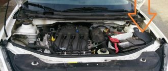
All relays (except for the relay for turning on the heated glass of the rear door), fuses of the engine management system are installed in the mounting block, which is located in the engine compartment of the car (on the left, behind the battery).
To gain access to the fuses and relays, press the latches from the side, back and front of the cover.
| Relay/fuse panel number | Relay/fuse number | Relay/fuse assignment |
| 299-1 | 231(A). | Fog light relay |
| 753(B) | Headlight washer pump relay | |
| 299-2 | 233 | Heater Fan Relay |
| 597-1 | F1 (60 A), F2 (60 A) | Electronic control unit for ABS and ESP systems |
| 597-3 | F1 (50 A). F2 (25 A) | Exterior light switch, interior fuse box |
| 784 | 700(A), | Cooling fan relay |
| 474(B) | Air conditioning compressor relay | |
| 1047 | F1 (30 A), | Relay box power supply |
| F2 (25 A) | Injection relay power supply | |
| F3 (5 A), | Power supply for injection system relay, ECU | |
| F4 (15 A) | Not used | |
| 238(A). | Injection blocking relay | |
| 236(B) | Fuel pump relay |
Do not replace fuses with jumpers or fuses that are rated for a different amperage - this may result in damage to electrical equipment and even a fire.
Attention!
The relay and fuse diagram may differ depending on the configuration and production date of the vehicle. Current diagrams of the mounting block are presented in the operating manual for the date of manufacture of the vehicle (download from the official website for a station wagon or van).
Relay and fuse box under the hood
Some systems are protected by fuses located in the engine compartment in block B.
Replacing the fuel pump Lada Largus
For those who have already changed the fuel filter on a Lada Largus themselves, replacing the fuel pump will not be difficult. Let's figure out step by step how this is done.
Please note that the fuel pump on the Lada Largus van changes slightly differently and we will discuss this at the very end of this article.
1. First of all, fold down the lower part of the rear seat to gain access to the fuel pump hatch.
2. Lift the plastic cover and move the carpet to the side.
3. Carefully remove the round fuel pump cover.
4. Disconnect the fuel pump power supply and start the engine. This is necessary to relieve pressure in the system. After running for 1-2 minutes, the engine will stall without fuel, and the fuel will be discharged on its own.
5. Now we squeeze the clamps and disconnect the fuel line from the top cover of the fuel module.
6. Unscrew the clamping ring, resting against the protrusions of the edge of the neck with a flat screwdriver. When the nut is loose, unscrew it completely by hand.
7. We take out the fuel module and at the same time carefully remove the fuel level indicator float so as not to bend it.
8. Disconnect the contact chip from the fuel pump.
9. Remove the lower part of the fuel module by prying the clamps with a screwdriver and disengaging them.
10. Remove the coarse filter from the fuel pump.
11. Disengage the latch from the guide and remove the fuel filter.
12. Heat it with a hairdryer and remove the tube from the fuel pump.
13. Install the new fuel pump in place. We put the tube in and heat it with a hairdryer so that the tube shrinks. If necessary, install a new tube.
We put everything back together in reverse order.
Lada Largus fuse diagram under the hood
The mounting block in vehicles of the Largus family serves as the location for all relays and part of the fuses. Of the latter, those that protect the circuits of the motor control system are presented. The fuses are marked with the letter F.
The block is located to the left of the battery. To get to it, press out the latches holding the cover on the side, back and front.
| Relay/fuse no. | Current (amps) | Relay/fuse assignment |
| 231(A). | Fog light relay | |
| 753(B) | Headlight washer pump relay | |
| 233 | Heater Fan Relay | |
| F1/F2 | 60 | Electronic control of ABS and ESP systems |
| F1/F2 | 50/25 | Exterior light switch, interior fuse box |
| 700(A), | Cooling fan relay | |
| 474(B) | Air conditioning compressor relay | |
| F1 | 30 | Relay box power supply |
| F2 | 25 | Injection relay power supply |
| F3 | 5 | Power supply for injection system relay, ECU |
| F4 | 15 | Not used |
| 238(A) | Injection blocking relay | |
| 236(B) | Fuel pump relay |
Purpose of relays and fuses in the mounting block located in the engine compartment
Note: The location of relays and fuses in the engine compartment may vary depending on the installed engine and vehicle modification.
LOCATION ON K4M ENGINE MODELS
K – Relay, F – Fuses
CIRCUIT BREAKERS
| Fuse designation (rated current, A) | Protected elements |
| F1 (15) | Not used |
| F2 (5) | Circuits: constant power supply to the engine control system ECU; windings of the main relay K5 of the engine control system |
| F3 (25) | Power circuits: relay K4 of the fuel pump and ignition coil; main relay K5 of the engine management system |
| F4 (30) | Cooling fan short circuit relay power circuit (on a vehicle without air conditioning) |
| F5 (40) | Power circuits: air conditioning relay K2; low speed short circuit relay for the cooling system fan (on a car with air conditioning); relay K1 high speed cooling fan (on a car with air conditioning) |
| F6 (25) and F7 (50) | ABS control unit circuits |
| F8 (60) | Circuits: power supply to the ignition switch and all consumers powered from the lock; left steering column switch |
| F9 (60) | Interior fuse box power supply circuit |
RELAY
| Designation | Name | Powered consumers |
| K1 | Cooling fan high speed relay (for vehicle with air conditioning) | Cooling fan motor |
| K2 | Air conditioner relay | Air conditioning compressor electromagnetic clutch |
| short circuit | Low speed cooling fan relay (for vehicle with air conditioning) or cooling fan relay (for vehicle without air conditioning) | Cooling fan electric motor (for a car with air conditioning - through a resistor) |
| K4 | Fuel pump and ignition coil relay | Fuel pump and ignition coil |
| K5 | Engine control system main relay | Oxygen concentration sensors (heating circuit): speed sensor; fuel injectors; adsorber purge solenoid valve; relay windings K1. KZ, K2; Engine control ECU |
| K6 | Not used | – |
| K7 | Fog light relay | Fog lamps |
| K8 | Heater Fan Relay | Heater fan motor |
LOCATION ON MODELS WITH VAZ-11189, VAZ-21129 ENGINES
CIRCUIT BREAKERS
*Only with motor 11189 **Only with motor 21129
RELAY
Other location options
| Relay/fuse panel number | Relay/fuse number | Relay/fuse assignment |
| 299-1 | 231(A). | Fog light relay |
| 753(B) | Headlight washer pump relay | |
| 299-2 | 233 | Heater Fan Relay |
| 597-1 | F1 (60 A), F2 (60 A) | Electronic control unit for ABS and ESP systems |
| 597-3 | F1 (50 A). F2 (25 A) | Exterior light switch, interior fuse box |
| 784 | 700(A), | Cooling fan relay |
| 474(B) | Air conditioning compressor relay | |
| 1047 | F1 (30 A), | Relay box power supply |
| F2 (25 A) | Injection relay power supply | |
| F3 (5 A), | Power supply for injection system relay, ECU | |
| F4 (15 A) | Not used | |
| 238(A). | Injection blocking relay | |
| 236(B) | Fuel pump relay |
Description of fuses for the Lada Largus car
Layout of relays - breakers:
| Designation | Who is responsible for what/what provides |
| K 1 | Fog lights (relay) |
| K2 | Headlight washer motor |
| K 3 | Radiator fan |
| K 4 | Electronic engine control unit, ABS, ESP |
| K5 | Light switch, interior lighting |
| K 6 | Stove fan |
| K 7 | Air conditioner cooler |
| K 8 | Fuel injectors (spray) |
| K9 | Fuel pump relay |
Fuse installation diagram:
| Marking/amperage | What he is responsible for (with description) |
| F (F-1) / 20 | Windshield wiper, lever speed control, rear window (door) defroster |
| F (F-2) / 5 | Dashboard, fuel pump, ECU, electronic powertrain control unit, fuel pump |
| F (F-3) / 10 | Stop signal |
| F (F-4) / 10 | Diagnostic connector, antenna, immobilizer, electrical control module |
| F (F-5) / 20 | Reservation |
| F (F-6) / 30 | Reservation |
| F (F-7) / 30 | Reservation |
| F (F-8) / 7.5 | Reservation |
| F (F-9) / 10 | Instrument panel, low beam headlights, left side |
| F (F-10) / 10 | Low beam relay, right side |
| F (F-11) / 10 | Instrument panel (visor), high beam, left headlight |
| F (F-12) / 10 | High beam, right headlight |
| F (F-13) / 30 | Rear door window motors |
| F (F-14) / 30 | Window lifters for front doors |
| F (F-15) / 10 | Electronic control unit ECU, ABS system, acceleration sensors, steering wheel angle sensors |
| F (F-16) / 15 | Heated front seats |
| F (F-17) / 15 | Sound signal |
| F (F-18) / 10 | Front and rear parking lights left side |
| F (F-19) / 10 | Reservation |
| F (F-20) / 10 | Side lights right side, glove compartment lighting, air conditioning, ventilation, double-glazed front doors, fog lights |
| F (F-21) / 5 | Heated front exterior mirrors |
| F (F-22) / 5 | Reservation |
| F (F-23) / 5 | Reservation |
| F (F-24) / 5 | Reservation |
| F (F-25) / 5 | Reservation |
| F (F-26) / 5 | SRS system |
| F (F-27) / 20 | Rear window wiper relay, alarm, reversing lights, central locking |
| F (F-28) / 15 | Interior lighting, energy saving mode |
| F (F-29) / 15 | Interior electrical equipment |
| F (F-30) / 20 | Electrical wiring, interior sensors |
| F (F-31) / 15 | Fog lights, relay |
| F (F-32) / 15 | Heated rear window |
| F (F-33) / 15 | Reservation |
| F (F-34) / 15 | Reservation |
| F (F-35) / 15 | Starter, generator |
| F (F-36) / 30 | Heating system engine, air conditioner |
| F (F-37) / 5 | Exterior mirror drive |
| F (F-38) / 15 | Cigarette lighter, radio |
| F (F-39) / 10 | Heating, air conditioning engine |
The price of an assembled assembly unit is from 2500 rubles, melting elements from 100 rubles, a set from 500 - 600 rubles.
Common signs of faulty fuses
- The battery is charged, power is supplied, but the units do not work;
- Increased temperature in the mounting block;
- A melted smell can be heard in the cabin;
- Indicators on the dashboard indicate a malfunction of the power unit.
Causes of fuse failure
- Long-term operation of a technical device without intermediate preventive maintenance, inspection, or replacement of worn elements;
- Mechanical damage, accident, impact, collision;
- Short circuit in the circuit;
- Damage to insulation, oxidation of terminals, loosening of contacts;
- Water entering the mounting block, condensation forming.
Block in the cabin
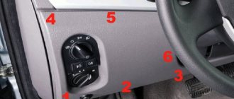
It is located on the left side of the dashboard, on the driver's side, behind the protective cover.
p, blockquote 4,0,0,0,0 —>
Photo - diagram
p, blockquote 5,0,0,0,0 —>
p, blockquote 6,0,1,0,0 —>
On the back of the protective cover, on some models, the current fuse assignment diagram will be printed.
p, blockquote 7,0,0,0,0 —>
Scheme
p, blockquote 8,0,0,0,0 —>
p, blockquote 9,0,0,0,0 —>
Description
p, blockquote 10,0,0,0,0 —>
| 1 | 20A Windshield wiper and washer, central electronic switching unit in the passenger compartment (UCC), power consumer relay unit (rear window heating relay control) |
| 2 | 5A Instrument cluster, engine control unit, fuel pump relay control, ERA-Glonass car terminal ('19-'20) |
| 3 | 10A Brake Lamp Switch, Auxiliary Brake Light |
| 4 | 10A Turn signals, diagnostic connector, transponder unit ('12-'16), daytime running light relay ('12-'16), central electronic switching unit (UCCU), immobilizer antenna, parking system control unit ('16-'16) '20) |
| 5 | Signal |
| 6 | Reserve |
| 7 | Alarm |
| 8 | Reserve |
| 9 | 10A Left headlight (low beam), instrument cluster, headlight washer pump ('12-'16) |
| 10 | 10A Right headlight (low beam) |
| 11 | 10A Left headlight (high beam), instrument cluster |
| 12 | 10A Right headlight (high beam) |
| 13 | 30A Rear windows |
| 14 | 30A Front windows |
| 15 | 10A Anti-lock system (ABS) control unit, acceleration sensor, steering wheel angle sensor |
| 16 | 15A Heated front seats |
| 17 | 15A Horn |
| 18 | 10A Left side parking light, license plate light ('16-'20), glove box light ('16-'20) |
| 19 | 10A Right side parking light, license plate light ('12-'16), glove box light ('12-'16), switches and interior lighting (instrument cluster, hazard warning switch, air conditioning control panel, audio system, central switch) lock, cigarette lighter, rear window heating switch, - driver's door window-lift switch, heating impulse switch, interior door handle lock switch), central electronic switching unit in the cabin (UCC) |
| 20 | 7.5A Rear fog light (left lamp), instrument cluster |
| 21 | 5A Heated mirrors |
| 22 | 5A '19-'20: Automotive terminal "ERA-Glonass" |
| 23 | Reserve |
| 24 | 5A '12-'16: Electric power steering pump |
| 25 | 5A '12-'16: LPG control system |
| 26 | 5A Control unit for airbags and seat belt pre-tensioners |
| 27 | 20A Rear wiper and washer, reversing lamps (right lamp), headlight washer pump ('12-'16), driver's seat belt horn ('16-'20) |
| 28 | 15A Audio system, instrument cluster, interior lighting (central lamp, 3rd row lamp), luggage compartment lighting, central electronic switching unit in the cabin (UCC) |
| 29 | 15A Diagnostic connector, central electronic switching unit in the passenger compartment (UCC) |
| 30 | 20A Central locking, central electronic switching unit in the passenger compartment (UCC) |
| 31 | 15A Front fog lights |
| 32 | 30A Heated rear window, heated mirrors |
| 33 | Reserve |
| 34 | Reserve |
| 35 | Reserve |
| 36 | 30A Heater, air conditioning control panel ('16-'20) |
| 37 | 5A Electric drive of external rear view mirrors |
| 38 | 10/15A Cigarette lighter , audio system |
| 39 | 30A '12-'18: Heater, air conditioning control panel |
| 10A '19-'20: Heater, car terminal "ERA-Glonass" |
Replacing fuses on Lada Largus
Preparatory stage:
- A set of new fuses;
- Rags;
- Additional lighting if there is not enough natural light;
- New relays to replace.
Algorithm of actions:
- We place the car on a flat platform, open the driver's door;
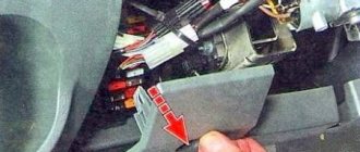
- From the end of the torpedo we snap off the plastic cover, under which there is a mounting block with fuses;
- Using plastic tweezers, remove each module one by one and check its serviceability. This is rational if we do not know the exact number of the faulty module.
In order to simplify the process of identifying and searching for modules on the board, there are markings and pinouts on the back of the cover. Insert a new one in place of the faulty fuse and snap the cover on.
Replacing modules in an additional unit is no more difficult than replacing the interior.
- Open the hood, in the upper left part of the engine compartment, behind the battery there is a mounting block;
- We unclip the plastic cover of the power supply unit and use pliers to remove the faulty fuse;
- If you need to replace the relay switch, then additionally disconnect the terminals from the limit switches.
Upon completion, install the housing cover of the mounting block in its original place. We start the engine and check the operation of the units.
The average service life of domestic fuses is 50 – 55 thousand km. Foreign analogues “nurse” for 5 – 10 thousand km. longer. If you encounter difficulties with installing the mounting block or replacing fuses, contact a specialist auto repair shop. The functionality of a number of mechanisms and units on a car depends on the quality of work.
Cigarette lighter fuse Lada Largus - where is it located on the diagram?
The Lada Largus cigarette lighter fuse is the most frequently burned fuse, which can cause a lot of inconvenience. In this material we will look at what fuse is on the Lada Largus cigarette lighter and where it is located.
Where is the cigarette lighter fuse on Lada Largus?
The Lada Largus cigarette lighter fuse is located in the mounting block in the car interior. The layout of the Lada Largus mounting block is shown in the photo:
In order to find a blown fuse, you need to open the driver's door and remove the cover of the mounting block. Next, using special tweezers, you can remove the burnt fuse and replace it with a new one.
In order to understand where the Lada Largus fuse is located, let's turn to the diagram.
Lada Largus fuse diagram for the cigarette lighter in the passenger compartment
The fuse for the cigarette lighter of the Lada Largus is located under number F38. At the bottom of the mounting block it is located in the third row, second from the bottom. In addition to the cigarette lighter, this fuse is responsible for the car's audio system.
What is the fuse for the cigarette lighter of Lada Largus?
The Lada Lagrus cigarette lighter is equipped with a Standard (Norma, Regular, Standart) fuse with a rating of 15A. Such a fuse can be purchased at any auto parts store, as it is suitable for a large number of cars, incl. for almost all AvtoVAZ cars.
Dimensions
Why does the Lada Largus cigarette lighter fuse light up?
If the car's electrical system is fully operational, then a common cause of the cigarette lighter fuse blowing is excessive load on the power wires.
This is due to the fact that the cigarette lighter connector of the Lada Largus is often used as a socket for connecting various accessories - for example, a compressor for inflating wheels, various chargers for gadgets (phone, recorder, laptop, etc.), voltage inverters, etc.
Often these devices consume a lot of current, and the wiring is of insufficient cross-section, so they overheat and the fuse simply blows.
However, if you do not use such devices, and the fuse continues to burn, then there is a short circuit somewhere. In this case, you need to sort out the wiring and only then replace the fuse with a new one.
Device diagram and tabular data
All the material we have indicated is valid for the modification of Lada Largus 2012-2014.
To provide access to the fusible links under the hood, you will need to press the latches of the mounting block cover and then remove it.
Here we see the block itself with the cover removed.
The purpose and characteristics of each of the fuses are summarized in the following table; this is the fuse diagram.
As already noted, the second fuse box is located on the left side of the panel, or rather behind the compartment cover. To access the inserts, you will need to remove this very cover, as shown in the following figure.
On the back of the cover is a fuse diagram that indicates the location of each fuse. It also contains spare inserts “A” with different current characteristics. To remove elements from the mounting sockets, there is a special tweezers “B”. It allows you to remove fuses with enviable ease when replacing them with new inserts.
The image shows the transcript of the inserts in tabular form.
Sources
- https://ZamenaRenault.ru/largus/elektrika-i-tormoza/predohraniteli.html
- https://xn--80aal0a.xn--80asehdb/do-my-self/repair/repair-lada-largus/307-blok-predohraniteley-i-rele-lada-largus.html
- https://rus-avtomir.ru/remont/predohraniteli-largus
- https://carqa.ru/info/predohraniteli-i-rele-lada-largus
- https://zen.yandex.ru/media/id/5c746b956dc7c000aeb0f93a/5dbdff3ac05c7100ae7d95a8
- https://largus-mcv.ru/html/predokhraniteli.html
- https://zapchasti.expert/predoxraniteli/predoxraniteli-na-lada-largus.html
