This car is very common on our roads. The all-wheel drive UAZ began its history in the second half of the last century and won wide love among motorists. For that time it was a wonderful car, which was popularly called “Loaf” because of the shape of the body.
On the 462nd model and its modifications (wagons, ambulances, cargo, minibuses), the operation of the electrical circuits of the most important structural elements of the car is protected using special fuses.
Electrical diagram
Description
p, blockquote 5,0,1,0,0 —>
| 1 | front lamp; |
| 2 | headlight; |
| 3 | special sign lamp (only for UAZ-3962); |
| 4 | heater fan electric motor (only for UAZ-3962, UAZ-2206); |
| 5 | hydraulic brake actuator warning light sensor; |
| 6 | sound signal; |
| 7 | side turn signal repeater; |
| 8 | turning headlight (only for UAZ-3962); |
| 9 | turning headlight switch; |
| 10 | cabin lighting; |
| 11 | warning lamp for turning on the parking brake system; |
| 12 | parking brake warning light switch; |
| 13 | windshield wiper motor; |
| 14 | wiper and washer motor switch; |
| 15 | speedometer; |
| 16 | signal lamp for turning on high beam headlights; |
| 17 | voltmeter; |
| 18 | oil pressure indicator; |
| 19 | oil pressure warning lamp; |
| 20 | coolant temperature indicator in the engine cylinder block; |
| 21 | warning lamp for emergency overheating of the coolant in the radiator; |
| 22 | fuel level indicator; |
| 23 | washer motor; |
| 24 | hazard switch; |
| 25 | direction indicator lamp; |
| 26 | warning lamp for the emergency condition of the hydraulic brake system; |
| 27 | ignition switch; |
| 28 | central light switch; |
| 29 | thermal fuse; |
| 30 | heater resistance; |
| 31 | heater fan motor switch; |
| 32 | headlight switch; |
| 33 | rear fog lamp switch; |
| 34 | fuse block; |
| 35 | plug socket; |
| 36 | unbalance solenoid valve; |
| 37 | turn signal switch; |
| 38 | sound signal button; |
| 39 | oil pressure warning light sensor; |
| 40 | sensor for warning light of emergency overheating of coolant in the radiator; |
| 41 | oil pressure indicator sensor; |
| 42 | coolant temperature indicator sensor in the cylinder block; |
| 43 | turn signal switch; |
| 44 | heater fuse (only for UAZ-3962, UAZ-2206); |
| 45 | heater fan electric motor switch (only for UAZ-3962, UAZ-2206); |
| 46 | heater fan motor switch resistance (only for UAZ-3962, UAZ-2206); |
| 47 | heater fan electric motor (only for UAZ-3962, UAZ-2206); |
| 48 | generator; |
| 49 | spark plug; |
| 50 | sensor-distributor; |
| 51 | ignition coil; |
| 52 | ground switch; |
| 53 | rechargeable battery; |
| 54 | lamp switch; |
| 55 | plug socket (only for UAZ-3962, UAZ-2206); |
| 56 | lampshade; |
| 57 | transistor switch; |
| 58 | emergency vibrator; |
| 59 | electronic carburetor control unit; |
| 60 | microswitch; |
| 61 | additional resistance; |
| 62 | additional starter relay; |
| 63 | solenoid valve; |
| 64 | starter; |
| 65 | fuel level indicator sensor in the tank; |
| 66 | brake light switch; |
| 67 | reverse light switch; |
| 68 | back lamp; |
| 69 | rear fog lamp; |
| 70 | license plate light; |
| 71 | reversing light; |
| 72 | trailer socket |
Blog about UAZ
To switch the main circuits of the car, a combined ignition switch is used, consisting of a contact part and a mechanical anti-theft device with a lock. When the engine is not running, all consumers are powered by the battery, and after the engine is started - by an alternating current generator with a built-in rectifier unit. When the generator is running, the battery is charged.
Electrical diagram of UAZ-31519-095 and UAZ-31519-195.
When the engine is idling, the rotation speed of the generator rotor and, accordingly, the supplied current are insufficient to provide power to powerful consumers, such as headlights, a windshield wiper, an electric heater fan, and an alarm system. In this mode, the battery will be discharged.
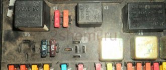
To protect the vehicle's external lighting electrical circuits from overload, a bimetallic fuse 29.3722 or similar is used, which is installed under the instrument panel on the left. Three 10 Amp fuses are installed in the PR103 fuse box, mounted on the partition of the engine compartment. They protect:
No. 1 - circuits of control devices; No. 2 - direction indicator circuits; No. 3 - alarm and sound signal circuits.
Electrical equipment
Each node is reliably protected from unexpected increases in current by special fuse links (fuses). They are assembled in a single mounting block, consisting of two lines, each of which contains 13 connectors with fuse links.
The compact unit is installed inside the car on the left side of the steering column. To make it convenient to inspect the elements of the block, a special backlight lamp with a built-in switch is fixed just above it.
In the engine compartment of the UAZ Hunter, another block is mounted, with strip-type fuses.
Each insert is responsible for a specific direction:
- starting switch;
- lighting fixtures outside the car;
- fuel filter heating;
- spark plug operation.
The purpose of the fuse links of the first and second blocks is to protect the electrical circuits of the equipment from overload and short circuit. Fuse housings come in different colors and are marked with the rated current.
The fuse links of the mounting block are installed in the following order.
| No. | What is he responsible for? | Note |
| F1 | Upper bar | Reserve |
| F2 | Side lighting | Right side of the body |
| F3 | Low beam | |
| F4 | Long range lighting | |
| F5 | Fog lights | |
| F6 | Lamp for illuminating the installation site of the mounting block | |
| F7 | Tail light brake lights | |
| F8 | Alarm | |
| F9 | Klaxon (beep) | |
| F10 | Rear license plate lamps and instrument lighting on the control panel | |
| F11 | Responsible for the cigarette lighter | |
| F12 | Rear fog lamp (if equipped) | |
| F13 | Reserve | |
| F14 | Bottom bar | |
| F15 | Side lighting | Left side of the body |
| F16 | Low beam | |
| F17 | Long range lighting | |
| F18 | Fog lights | |
| F19 | Reverse (white light) | |
| F20 | Direction indicators (right and left) | |
| F21 | Heater operation | |
| F22 | Windshield wiper motor and washers | |
| F23 | Interior lighting of the car and connecting the engine compartment lamp | |
| F24 | Reserve | |
| F25 | Operation of devices and alarms (sensors) | |
| F26 | Reserve |
Additional block
The manufacturer equipped modifications with a diesel power unit with an additional unit. It contains fuses and relays. It is installed on the side wall of the engine compartment.
The fuse block of the UAZ Hunter 315195 diesel has the following fusible elements:
- F1 and F2 are fusible elements of the on-board network. They have a permissible load of 30 Amps;
- F3 – fusible element of the fuel heating relay. Nominal 25 Ampere;
- F4 – diagnostic fuse with a permissible load of 5 amperes;
- F5 – electric starter relay protection – 20 Amperes;
- F6 – protection of the sensor that controls air mass flow by the power plant – 10A;
- F7 – fusible element of the electronic control unit – 5 A;
- F8, F9, F10 – protection of main relays. the elements are rated 15, 10 and 25 Amps respectively.
What components and assemblies are protected by fuses?
The mounting fuse block on the UAZ Hunter provides reliable protection for the following components:
- Side lights and main vehicle lighting.
- Operation of turn signals.
- Cigarette lighter.
- Sound accompaniment (horn).
- Windshield wiper operation.
- Car interior lighting.
- Stop lights.
- Heating system of the car.
- Audio system and radio equipment.
- Heating system pump.
- Illumination and operation of instruments on the panel.
- Backup equipment.
The UAZ Hunter is equipped with fuses for various components located on a block in the vehicle interior. But there are two more relays that are located under the hood of the car:
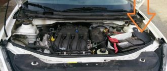
The performance of the power unit depends on the correct operation of these relays, since 12V voltage is distributed through the main power supply to all electrical components of the car and sensors, and the fuel pump relay supplies energy to the fuel pump and oxygen sensor.
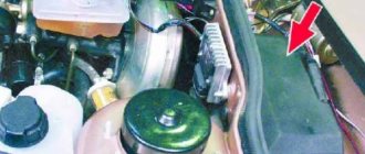
In appearance, both relays are completely identical, even the catalog number is the same. They are installed on the right side of the brake booster on the shield above the car engine.
You can distinguish relays from each other by the wires that connect to them. The main ECU relay is approached by wires with a cross-section larger than that of the electric fuel pump. Two fuse links are installed near them. They are shaped like a knife. One, red, ensures the operation of the ECU electrical circuit from the ignition system, the other, yellow, protects the circuits from the battery, fuel pump and oxygen sensor.
The installation location of the two relays was chosen well in terms of maintenance, but it is in this place that they are exposed to running water after rain and condensation. Therefore, they must be removed periodically, at least once a year, and the contacts must be cleaned from corrosion.
UAZ Hunter cars with diesel engines are additionally equipped with a relay and fuse box, as shown in the diagram.
Proper operation of fuses is an important component of the entire vehicle system. Failure or incorrect operation of at least one of them allows you to timely identify the impending danger and eliminate the malfunction.
This helps to extend the life of individual components and the vehicle as a whole, and also increases the safety of the driver, passengers inside the car and other road users.
Verified wiring diagram for UAZ 452: Loaf Loaf friend, comrade and Tablet
The UAZ-452 has received a variety of affectionate nicknames over the years of operation: “Loaf” and “Loaf” - for its external resemblance to a bread brick, “Tablet” - for reliable service in medical organizations.
It is noteworthy that its design and individual systems - transmission, body or wiring diagram of the UAZ 452 turned out to be quite durable.
Perhaps this was the only car in those years capable of reaching the most remote places for humanitarian purposes.
The famous Bukhanka has become a multi-purpose vehicle for rural areas
Meet UAZ 452
The car was a cargo-passenger version of an off-road vehicle with a 4x4 wheel arrangement. The Ulyanovsk Automobile Plant mastered production of the model back in 1965.
You can evaluate its capabilities by watching the following video:
The UAZ 452 is capable of transporting cargo weighing up to 700 kg in the back. In addition, it can tow a trailer weighing 850 kg. The vehicle became very popular not only in Russian off-road conditions, but was also successfully used in large cities in various capacities (pictured in the article).
In particular:
- Like a traffic police car;
- As a fire engine;
- Ambulance car;
- Grocery store;
- Utility vehicle, etc.
The famous Barefoot on the basis of UAZ 452 - a road train in the Izmailovo Central Park of Culture and Culture
Electronic components
Modern color wiring diagram of UAZ 452
The electrical wiring of the UAZ 452 was a simple single-wire circuit.
Structurally, it had the following solutions:
- The role of the second wire was played by the metal body and the components and assemblies attached to it;
- All electronic components and actuators had a “-” displayed on the housing. The cost of such a solution justified the imperfection of the scheme.
For reference: The instructions provided for regular checking of contacts. When oxidized, they should have been cleaned with sandpaper.
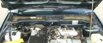
Power unit
The engine compartment is located directly inside the car, as this is due to its design.
Access to components and assemblies is also provided from the passenger compartment by removing the cover, which:
- Provided protection for the driver and passengers from the penetration of exhaust gases;
- Protected from dust and dirt;
- Served as an additional heating element (passive - from heating).
The high engine layout contributes to the vehicle's cross-country ability in off-road conditions
The previously used engine from Pobeda was replaced with a more modern engine from the 21st Volga. This was facilitated by the launch of a production line at the Zavolzhsky Motor Plant in 1964.
Passive vehicle safety
The design of the "Baton" with a cabover layout also initially raised a number of questions regarding safety. However, a series of crash tests conducted back in 1971 at the Dmitrov test site proved that in most emergency situations the driver and passengers of the UAZ 452 have a chance to avoid injury.
A striking example of comprehensive testing of “Tablets”
Features of electrical equipment
For designers, a more difficult process in those years was to find high-quality components to equip the ignition and lighting systems.
This can be clearly seen from the filling of the cabin:
- vehicle system controls;
- control devices.
Due to a shortage of controls, the UAZ received rather “variegated” elements
External lighting
Everything that could be obtained was used to ensure uninterrupted supplies to the factory conveyor.
In particular:
- from the predecessor of the Bukhanka, the GAZ-69, the factory workers borrowed a foot-operated light switch;
- From GAZ-24 headlights, etc.
The design of the GAZ-69 switch was successfully used on the 452
Ignition system
Since the Volgov engine was installed on Loaves and Bukhanki, the UAZ 452 wiring for the ignition system was almost completely copied from it.
The simplicity of the design made it easy to maintain the car away from garage conditions
Finally
Many of us remember the legendary car.
Therefore, his appearance at the show dedicated to the Olympic Games was perceived as part of our glorious history of the development of the domestic automobile industry.
The loaf was awarded participation in the 2014 Olympics
Where is the fuel pump relay located?
The fuel pump relay is a device that supplies or cuts power to the fuel pump. It controls the fuel pump and performs a number of additional functions depending on the make of the car.
Typically, in “loaves” the fuel pump relay is installed in the area of the injection control unit, under the hood, behind the battery. Sometimes it can be found under the dashboard near the fuses.
This is interesting: Do-it-yourself UAZ Bukhanka tuning: upgrading the engine, interior and suspension
Where is the charging relay located?
The charging relay consists of a reverse current relay, a regulator and a limiter. The reverse current relay turns the generator on when its voltage increases, and turns it off when the battery voltage increases.
The regulator controls and limits the current within 13.8 - 14.8 V , and regulates the charging current. The limiter protects the generator from overloads, working on a similar principle to the voltage regulator - it includes additional resistance in the winding circuit as the current increases.
The charging relay works in conjunction with the alternator under the engine hood on the right side.
Where is the starter relay located?
There are two types of starters in UAZ - 42.3708 and 4211.3708–01 . They themselves are installed on the left side of the engine (in the direction of travel of the car).
The starters are equipped with an electromagnetic traction relay and a lever drive with a roller freewheel clutch. The blocking relay is located in the medical compartment and serves to prevent the starter from turning on when the power source is connected.
The wire from the relay goes to the central contact of the variator (with three coils) or to the coil connection contact (with two coils). This helps to strengthen the spark during engine starting.
Where is the turn signal relay located?
In UAZ vehicles, the turn signal circuit includes a steering switch, a turn relay, an hazard warning light and six bulbs.
This system is protected from overloads by several fuses:
- F8 – 10 A (for alarm);
- F20 – 7.5 A (for direction indicators).
Turn signals without a relay will not blink , so its malfunction is easy to determine.
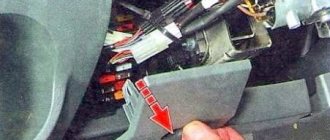
It is located in the mounting block, on the left side, at the driver’s feet. In ambulances and utility vehicles such as UAZ, the turn relay is installed on the partition, behind the driver's seat.
If the relay malfunctions, it must be removed, and the use of metal objects is not allowed.
Description
You can order Thermal relay UAZ (A20) 469-3722220-02 online right now. To do this, simply add the item to your cart or use the “Order a call back” option. Our specialists will contact you immediately and advise you on all questions!
We offer to purchase spare parts for UAZ vehicles, which are distinguished by their increased cross-country ability, ease of maintenance, as well as reasonable cost of components. Here you can find a wide range of products such as UAZ bumpers, UAZ locks and much more.
- availability of all necessary components in stock, which significantly speeds up the completion of each order
- there are no intermediaries, so our prices are always competitive
- high quality products, only original spare parts
- delivery of orders throughout the Russian Federation/ul>
If necessary, the customer can make payment upon receipt of the goods. In addition, our customers can always find out up-to-date information about the availability of certain spare parts. If you doubt your choice or cannot select the components yourself, our employees will certainly provide you with professional advice and help you make your choice. You can ask our manager any questions by calling 8 (800) 350-70-56 or using the feedback form.
Thermal relay UAZ (A20) 469-3722220-02 is currently in stock in our online store and ready for shipment. We deliver throughout Russia using transport companies and EMS services.
Fuses and relays
General layout
Designation
- fuse box;
- turn signal switch;
- ABS lamp control relay;
- high beam relay;
- low beam relay;
- windshield wiper switch;
- rear fog lamp relay;
- starter relay.
Rear fog lamp relay 7 is located on the front panel rail extension under the instrument panel in the area where the right headlight is located. In the area of the brake pedal bracket there is a windshield wiper breaker 6, high beam relay 4, low beam relay 5.
The fuse box is located on the left under the instrument panel and has three separate mounting inserts.
p, blockquote 10,1,0,0,0 —>
Scheme
Purpose
For cars with ZMZ-4091 Euro-3 engine.
F1 at 10 amperes, pin I - Warning lamp unit, hazard warning lights, speedometer, instrument cluster, ABS system sensors, if installed on the vehicle. F1 for 10 amperes, contact II - Reserve. F2 10 ampere, pin III - Alarm, sound signal. F2 at 10 amps, pin IV - Recirculation pump, heater switch, reverse light switch. F3 10 amp, pin V - Integrated microprocessor engine control system, ignition switch. F3 10 ampere, pin VI - Ignition switch, thermobimetallic fuse.
p, blockquote 15,0,0,1,0 —>
For cars with ZMZ-40911 Euro-4 engine.
F1 at 10 amperes, pin I - Warning lamp unit, hazard warning lights, speedometer, instrument cluster, ABS system sensors, if installed on the vehicle. F1 for 10 amperes, contact II - Reserve. F2 10 Amp Pin III - Turn Signal Switch, Hazard Light, Plug Socket. F2 at 10 amps, pin IV - Recirculation pump, heater switch, reverse light switch. F3 10 amp, pin V - Integrated microprocessor engine control system, ignition switch. F3 10 ampere, pin VI - Ignition switch, thermobimetallic fuse.
The ABS system fuses are located on the bulkhead behind the driver's seat at 25A or 40A.
p, blockquote 20,0,0,0,1 —>
Detailed explanation with photos, electrical diagram of fuse and relay blocks for UAZ cars.
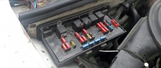
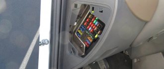
Two fuse blocks with thirteen fuses each are located under the instrument panel to the left of the steering column. Illumination when working in the area of the blocks is ensured by turning on the interior lighting lamp located in the upper part of the fuse block mounting bracket.
The power fuse block is located on the front panel, under the hood. On UAZ-315143, UAZ-315148 vehicles there is a block with four fuses (Fig. 1), on other vehicles - with two (Fig. 2).
Before replacing a blown fuse, find out the cause of its burning and eliminate it. When operating a vehicle and when checking the electrical circuit, it is not allowed to use fuses that are not provided for in the design, and also to short the wires to ground (check the serviceability of the circuits “for a spark”).
| Designation | Current strength, A | Protected Circuits |
| Upper block | ||
| F1 | 25 | Reserve |
| F2 | 5 | Side lights (starboard side) |
| F3 | 7,5 | Headlight - low beam (right side) |
| F4 | 10 | Headlight - high beam (right side) |
| F5 | 7,5 | Fog lamp (right side) |
| F6 | 5 | Fuse box light, portable lamp socket |
| F7 | 7,5 | Brake lights |
| F8 | 10 | Direction indicators in hazard warning mode |
| F9 | 20 | Sound signal |
| F10 | 7,5 | License plate lights, instrument lighting, switches |
| F11 | 15 | Cigarette lighter |
| F12 | 5 | Rear fog light |
| F13 | 10 | Reserve (radio equipment) |
| Bottom block | ||
| F14 | 25 | Reserve |
| F15 | 5 | Side lights (left side) |
| F16 | 7,5 | Headlight - low beam (left side) |
| F17 | 10 | Headlight - high beam (left side), high beam headlight indicator |
| F18 | 7,5 | Fog lamp (left side) |
| F19 | 5 | Reversing light |
| F20 | 7,5 | Turn signals in maneuver mode |
| F21 | 10 | Heater |
| F22 | 20 | Electric motor for windshield wiper, windshield washer |
| F23 | 7,5 | Interior lamps, engine compartment lamp |
| F24 | 15 | Reserve |
| F25 | 5 | Devices, signaling devices |
| F26 | 10 | Additional heating system pump (UAZ-315148) |
1-4 - fuses
| Designation | Current strength, A | Protected Circuits |
| 1 | 90 | Terminal "30" start switch |
| 2 | 40 | Outdoor Lighting |
| 3 | 40 | Fuel filter heating |
| 4 | 90/60 | Glow plugs (UAZ-315148/UAZ-315143) |
Rice. 2. Power fuse block
: 1-2 - fuses
The all-wheel drive vehicle UAZ-452 (“loaf”) appeared in the 60s of the last century, and is still popular. But UAZ often breaks down, and in order to eliminate the malfunction, you need to know the location of its main relays.
UAZ-452 wiring diagram, do-it-yourself wiring replacement: instructions, photos and
UAZ 452 wiring diagram: features of lighting and ignition system control
The famous “loaf” - the multi-purpose UAZ 452 appeared in the line of the Ulyanovsk Automobile Plant back in 1965 and remains on the assembly line to this day. Of course, over the years of production, the manufacturer has modernized the car in every possible way - the suspension, engine, and wiring diagram of the UAZ 452 have changed, but in general, the entire design has remained the same.
Electrical wiring of UAZ 452: reliable single-wire circuit
Differences between electrical systems
Modernizations affected the service conditions of cars of different years of production.
The car does not cause any particular difficulties when carrying out routine maintenance with your own hands, however, the electrical systems have differences, the reasons for which were:
- Modifications of power units;
- Changes to the instrument panel;
- Installations of lighting and side lights of a new generation.
Original photo of the 1974 model documentation included with the car
Period from 1965 to 1984
During this period, the automaker equipped its products with electrical components available to the domestic industry. Some of them were known for a long time, others were experimental, evidenced by previous years, and which had to prove their suitability.
Connection diagram for headlights on UAZ 452 first editions
Lighting control
In particular, the controls and a number of main units migrated from its predecessor, the GAZ-69. Thanks to this, the price of the car remained the same.
On models of the first years of production, a foot light switch was installed, which had several operating modes:
- The first position activated the circuit for switching the low beam headlights and side lights;
- In the second position, the low and high beam headlight circuit was activated.
For reference: Turning on the headlights (low or high beam) led to the turning off of the front side lights.
Foot switch for headlights and parking lights
The modernized light switch has a different operating algorithm:
- The first position supplies power to the side lights only;
- The second position is side lights and low (high) beam headlights.
Caution: This algorithm with non-switchable dimensions is a mandatory requirement for passing MOT.
The factory instructions give recommendations for reworking the old circuit, in which it is important not to mix up the contacts of the foot switch
The most correct option is to replace the old switch with a modern one, which uses only 3 contact groups.
Also, on older versions of the “452” there was no alarm, so in the electrical diagram:
- An RS-57 breaker relay was installed (mounted in the wiring gap from the “+” terminal of the battery to the direction indicator switch);
- The middle contact of the relay closed the indicator light on the instrument panel.
Ignition system
Ignition of UAZ 452 model 1968
Also on the “452” contact ignition was installed:
- The “+” wire from the battery supplied power to the ignition coil;
- From the coil, the high-voltage wire transmitted the impulse to the breaker (distributor) and further to the spark plugs.
Safety devices
All safety devices are collected in one place on a single block, which is located in the car interior under the dashboard to the left of the driver's seat.
If it is necessary to check the unit's fuses at night, a lamp is provided at the bottom of the panel board. It is not allowed to operate protective devices that are not provided for by the vehicle design, and also to check for the presence of a spark (short the wiring to ground).
Advice. Before installing a new fuse, you should understand the reason for its failure, eliminate it, and only then replace it with a new one.
What fuses are installed in the mounting block?
The electronic circuit of the car includes the following structural components and parts:
- power source (battery);
- fuel pump;
- fuel purification filter;
- nozzles;
- the engine control unit;
- coil and spark plugs;
- idle speed, crankshaft, and throttle sensors;
- tachometer;
- fan for cooling the radiator;
- fan motor control relay;
- control indicator of the performance of the vehicle’s power unit;
- diagnostic connector.
The “Loaf” fuse mounting block is presented in the form of a ruler with protective devices, which is secured to the car frame with a simple nut. If malfunctions begin to appear in the operation of the car’s electrical unit, the first thing to do is check the functionality of the fuse responsible for a specific electronic device. If the protection elements of the mounting block are working properly, then you need to check the functionality of the electrical equipment itself. If it is also in order, then the option remains to examine the electrical part of the equipment for integrity using a device - a tester.
Additional block under the hood
But, on the UAZ Patriot, the matter is not complete with one fuse block; under the hood there is a second one - an additional mounting block with other, no less important electrical fuses and relays responsible for such components as: starter, fuel pump, ABS, and other systems. The currents here are higher, there is even an 80 A fuse! Thus, if suddenly the electric cooling fan on your UAZ Patriot suddenly fails, the first thing you should do is check the corresponding fuse inside the unit, which is located in the engine compartment.
The mounting block under the hood can be of two types: old type, new type. Just like the interior fuse blocks, they differ in the location of the elements, as well as in other aspects.
Some relays and electrical fuses may be missing inside the mounting block, this depends on the vehicle’s equipment, as well as its year of manufacture.
In addition to this unit, under the hood - on the opposite side - there can be another one - an additional one, which ensures the operation of the air conditioner. If the UAZ Patriot has a diesel engine, then a relay and a fuse for special diesel glow plugs are installed in this place. A diesel engine needs such spark plugs only for starting in winter.