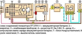
VAZ 2107 (Lada 2107) rear-wheel drive sedan which was produced in 1982, 1983, 1984, 1985, 1986, 1987, 1988, 1989, 1990, 1991, 1992, 1993, 1994, 1995, 1996, 1997, 1998, 1999, 2000, 2001 , 2002, 2003, 2004, 2005, 2006, 2007, 2008, 2009, 2010, 2011 and 2012 mainly with gasoline engines ( injector, carburetor ). The VAZ 2105, 2104 models are assembled on a common platform with the 2107, so the design of their blocks is largely the same. In this publication you will find a description of fuses and relays of VAZ 2107, 2105, 2104 with a block diagram and photo examples of execution. Note the fuse responsible for the cigarette lighter. In conclusion, we suggest that you familiarize yourself with the electrical connection diagram of the fuse box.
Fuse and relay box
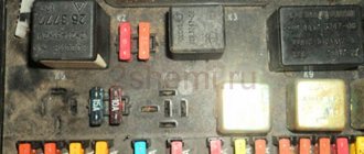
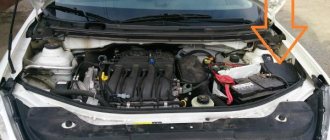
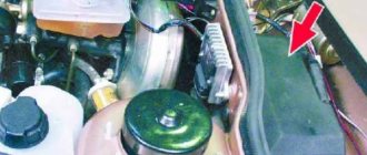
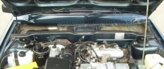
The main block with fuses and relays is located under the hood and can be made in 2 versions (old and new). The current diagram will be printed on the block cover.
Option 1
Scheme
Option 2
Installed on cars of early production years, here the fuses are cylindrical.
Scheme
Description
Circuit breakers
| 1 | 8/10A Heater motor Reversing light lamps Rear window heating switch on Rear window heating switch relay (winding) Rear window wiper motor (2104) Rear window washer pump motor (2104) |
| 2 | 8/10A Windshield wiper and washer motor Headlight wiper and washer motor Windshield wiper relay Headlight wiper and washer relay |
| 3 | 8/10A Reserve |
| 4 | 8/10A Reserve |
| 5 | 16/20A Rear window heating element and heating relay |
| 6 | 8/10A Cigarette lighter Socket for portable lamp Clock |
| 7 | 16/20A Sound signals Signal relay Electric radiator cooling fan relay (contacts) Radiator cooling fan electric motor |
| 8 | 8/10A Hazard switch with warning lamp Relay-breaker for direction indicators and hazard lights Turn signal indicator (in hazard mode) Turn indicators (in hazard mode) |
| 9 | 8/10A Generator Voltage Regulator |
| 9 | 8/7.5A Rear fog lamps and their indicator |
| 10 | 8/10A Turn signals (in turn signal mode) Relay - turn signal switch Turn signal indicator Pneumatic valve control system Tachometer Fuel gauge Fuel reserve indicator Parking brake indicator Insufficient oil pressure indicator in the engine lubrication system Coolant temperature indicator Voltmeter Service brake emergency indicator systems Battery charge indicator Carburetor air damper closed indicator Electric fan relay (winding) Electric fan thermal switch Generator excitation winding (generator 37.3701) |
| 11 | 8/10A Interior lamp Brake lamp Luggage compartment lamp |
| 12 | 8/10A High beam headlights (right headlight) Relay for windshield wipers and headlight washers (relay coil) |
| 13 | 8/10A High beam headlights (left headlight) High beam indicator |
| 14 | 8/10A Front side light (left headlight) Rear side light (right light) License plate lights Engine compartment lamp Side light indicator |
| 15 | 8/10A Front side light (right headlight) Rear side light (left light) Cigarette lighter lamp Instrument lighting lamp Glove box lighting lamp Clock (lighting lamp) |
| 16 | 8/10A Low beam headlights (right headlight unit) Relay for windshield wipers and headlight washers (relay coil) |
| 17 | 8/10A Low beam headlights (left block headlight) |
| 18 | Spare |
| 19 | Spare |
| 20 | Spare |
| 21 | Spare |
The cigarette lighter is controlled by fuse number 6 at 8 or 10A.
Relay
| K1 | Relay for turning on the heated rear window (904.3747-10 / 2105 -3747210-18, 2107 -3747210-12) | ||
| K2 | Headlight cleaner and washer relay (904.3747 / 2105 -3747210-08, 2107 -3747210-02) | ||
| K3 | Relay for turning on sound signals (904.3747-10 / 2105 -3747210-18, 2107 -3747210-12) | ||
| K4 | Relay for turning on the electric cooling fan (not used since 2000) (904.3747-10 / 2105 -3747210-18, 2107 -3747210-12) | ||
| K5 | Relay for high beam headlights (904.3747-10 / 2105 -3747210-18, 2107 -3747210-12) | ||
| K6 | Relay for low beam headlights (904.3747-10 / 2105 -3747210-18, 2107 -3747210-12) | ||
VAZ 2107, 2105, 2104 - fuses and relays
VAZ 2107 (Lada 2107) rear-wheel drive sedan which was produced in 1982, 1983, 1984, 1985, 1986, 1987, 1988, 1989, 1990, 1991, 1992, 1993, 1994, 1995, 1996, 1997, 1998, 1999, 2000, 2001 , 2002, 2003, 2004, 2005, 2006, 2007, 2008, 2009, 2010, 2011 and 2012 mainly with gasoline engines ( injector, carburetor ). The VAZ 2105, 2104 models are assembled on a common platform with the 2107, so the design of their blocks is largely the same. In this publication you will find a description of fuses and relays of VAZ 2107, 2105, 2104 with a block diagram and photo examples of execution. Note the fuse responsible for the cigarette lighter. In conclusion, we suggest that you familiarize yourself with the electrical connection diagram of the fuse box.
p, blockquote 1,0,0,0,0 —>
p, blockquote 2,0,0,0,0 —>
Additional block
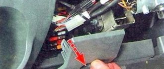
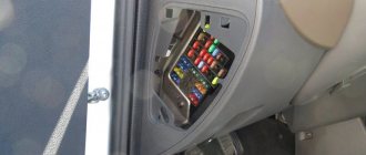
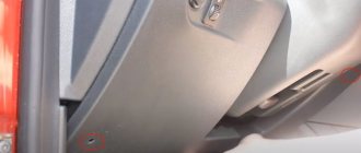
It is installed in injection models under the glove compartment in the car.
Scheme
Purpose
- 15A Main Relay Fuse
- Main relay
- 15A Injection system power supply fuse (non-switchable voltage input)
- 15A Fuse for electric fuel pump relay
- Electric fuel pump relay
- Cooling system electric fan relay
Fuse box VAZ 2104 2105
Where is the VAZ fuse mounting block located: 2104, 2105 (carburetor, injector)
The mounting block is located in the engine compartment on the right side and is attached to the front panel. The mounting block is closed on top with a lid on which symbols for the purpose of the relay, fuse numbers and the circuits they protect are printed. Most of the vehicle's electrical circuits are protected by fuses installed in the mounting block.
| Fuse number | Current strength, A | Protected Circuits |
| F1 | 10 | Tail lights (reversing lights). Heater motor Warning lamp and rear window heating relay (winding) |
| F2 | 10 | Electric motors for the windshield wiper and washer pump. Windshield wiper relay |
| F3 | 10 | Spare |
| F4 | 10 | Spare |
| F5 | 20 | Rear window heating element and heating relay (contacts) |
| F6 | 10 | Cigarette lighter. Portable lamp socket |
| F7 | 20 | Sound signals and relay for turning on sound signals. Engine cooling fan motor and motor switch relay (contacts) |
| F8 | 10 | Direction indicators in hazard warning mode. Switch and relay-interrupter for direction indicators and hazard warning lights in emergency mode |
| F9 | 7.5 | Generator voltage regulator (on vehicles with G-222 generator) |
| F10 | 10 | Turn indicators in turn signal mode and corresponding indicator lamp. Turn signal interrupter relay. Turn signal indicator Tachometer Fuel level indicator. Coolant temperature gauge. Voltmeter. Fan motor activation relay (winding). Battery charge indicator lamp. Indicator lamps for fuel reserve and parking brake activation. Warning lamps for emergency drop in oil pressure and insufficient brake fluid level. Indicator lamp for turning on the parking brake. Indicator lamp for covering the carburetor air damper (for a carburetor engine). Electric fan thermal switch. Carburetor pneumatic valve control system Generator excitation winding (generator 37.3701) |
| F11 | 10 | Rear lights (brake lamps). Body interior light |
| F12 | 10 | Right headlight (high beam). Winding of the relay for turning on the headlight cleaners (with the high beams on) |
| F13 | 10 | Left headlight (high beam). Indicator lamp for high beam headlights |
| F14 | 10 | Left headlight (side light). Right rear light (side light). License plate lights. Engine compartment lamp Indicator lamp for turning on side lights |
| F15 | 10 | Right headlight (side light). Left rear light (side light). Cigarette lighter lamp. Instrument lighting lamp. Glove compartment lamp |
| F16 | 10 | Right headlight (low beam). Winding of the relay for turning on the headlight cleaners (with the low beam on) |
| F17 | 10 | Left headlight (low beam) |
Mounting block connection diagram:
P1 — relay for turning on the heated rear window; P2 - relay for turning on headlight cleaners and washers; PЗ - relay for turning on sound signals; P4 - relay for switching on the electric motor of the engine cooling system fan; P5 - headlight high beam relay; P6 — headlight low beam relay; A - the order of conditional numbering of plugs in the mounting block blocks. The outer number with the letter “Ш” in the plug designation is the block number, and the inner number is the conventional number of the plug. The plugs of the blocks without color marking are conventionally shown in brown
Location of relays and fuses in the mounting block : 1 - relay for turning on the heated rear window; 2 — place for installing a relay for turning on headlight cleaners and washers (the relay is installed on some manufactured cars); 3 — mounting jumper in place of the relay for turning on sound signals (in a variant, a relay is installed); 4 — mounting jumper in place of the relay for turning on the electric motor of the cooling system fan (in a variant version, a relay is installed); 5 — relay for turning on the high beam headlights; 6 — relay for turning on low beam headlights; F1-F17 - fuses (circuits protected by pin-type fuses are indicated in the table above).
Electrical equipment that consumes high current during operation is connected through relays that protect switch contacts from overload. To replace pin fuses and relays, special plastic tweezers are provided in the mounting block. Fuses of different ratings are painted in different colors; In addition, the fuse is marked with a numerical value of the current for which it is designed (rated value). The color of the fuse body and its correspondence to the rating 20A - Yellow 15A - Blue 10A - Red 7.5A - Brown
Source
Additional items
Under the hood
Additional headlight wiper fuses (2A rating) protect the motor windings. They are located on the supply wires next to the gearmotors.
The starter activation relay 113.3747 or 90.3747-10 is located in the engine compartment on the right mudguard.
In the cabin
The windshield wiper relay (PC-514) is mounted under the panel on the left under the trim.
The ignition relay and the hazard warning and turn signal relays are installed on the front panel behind the instrument panel. The ignition relay (113.3747-10 or 90.3747-10) and the hazard warning and turn signal relays (23.3747 or 231.3747) have a bracket for direct mounting on the body.
The fog lamp fuse is located in the gear shift compartment, not far from the radio.
Block under the hood
The VAZ 2104 is equipped with a fuse block (FB), which is also called a mounting block, located under the hood on the passenger side. The node contains not only protective elements, but also relays responsible for switching certain devices.
How to identify a blown fuse
If any problems arise with the electrical part of the “four”, you first need to look into the mounting block and check the integrity of the fuses and only then proceed to a more detailed troubleshooting. The design of the protective element may differ depending on the power supply installed on the machine. You can check the fuse link for failure in the following ways:
Visual inspection
The fuses are designed in such a way that their functionality can be determined by their appearance. For cylindrical elements, a special insert is located on the outside and its damage cannot be ignored. The flag elements are equipped with a fusible insert inside, but thanks to the transparent case, its condition can be assessed visually through the light. A blown fuse will have a broken insert.
Checking with a multimeter or tester
Using the device, the fuse can be checked by voltage and resistance. In the first case, the part is diagnosed directly in the mounting block. To do this, do the following:
- We set the device to the voltage measurement limit.
- We turn on a circuit in the car that is protected by a fusible link (stove, headlights, etc.).
- Using a multimeter or a tester (test light), we check the voltage at one fuse contact, and then at the other. If there is no voltage at one of the terminals, this will mean that the fuse has blown and requires replacement.
Fuse box in the cabin of the "four"
Most modifications of the VAZ 2104 are equipped with only one power supply unit - in the engine compartment. However, the injection versions of this car have an additional unit, which is located in the cabin under the glove box. This block is a bar with several elements located on it:
- main relay;
- fuel pump relay;
- fan relay.
Fuse links provide protection:
- main relay;
- electric fuel pump;
- electronic engine control unit.
How to remove the fuse box
The need to remove the power supply may arise when replacing a relay or protective elements of the motor control system. To do this, the bar itself on which the parts are held is dismantled. The procedure goes as follows:
- We de-energize the on-board network by removing the negative terminal of the battery.
- We unscrew the fasteners of the bracket to the body.
The connection of elements in the additional block of the VAZ 2104 is made using connectors and in case of problems, only the parts are changed.
To increase the reliability of the electrical equipment of the VAZ Four, it is advisable to install a new model of the fuse box. If this is not possible, then periodic repairs of the old unit can be performed with a minimum set of tools and without special knowledge. It will be enough to read the step-by-step instructions and follow them during the repair process.
Source
