What are the reasons for the charging failure, how to fix the problem on the road or in the garage - this is discussed in this manual. The electrical circuit of the LADA Niva 4×4 is built according to a classic layout and has undergone virtually no changes since the start of production. Why, knowing its weak points and moving from the obvious to the complex. You will quickly find the root cause.
Generator connection principle, drawing:
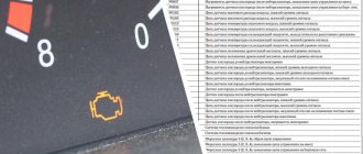
Basic information about the state of the charger can be obtained from the behavior of the instrument cluster - flashing of the indicator, emergency operation of electrical equipment (headlights, interior lighting, heater) and the engine.
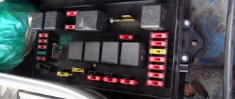
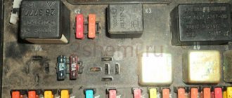
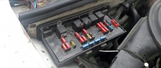
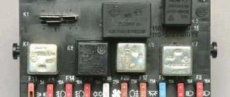
Main and additional fuse blocks
Heater fan, rear window defroster, rear wiper and washer system, windshield washer pump
Steering column switch, windshield wipers, hazard warning lights, breaker relay (in turn signal mode), reverse light, instrument cluster (coolant temperature gauge, fuel level gauge, tachometer, warning lights: turn indicators, differential lock, parking brake, emergency condition of the working brake system, insufficient oil pressure, fuel reserve, battery charge)
Right headlight (high beam)
Left headlight (low beam)
Right headlight (low beam)
Side light lamps in the left front and left rear lights, license plate lights, side light control lamp
Hazard switch, breaker relay (in hazard mode), tailgate defroster relay contacts
Sound signal, interior lamps, brake lamps in the rear lights
Fog light relay contacts in rear lights
| F11 (8A) | Turn signal lamps and relay-breaker for turn signals and hazard warning lights (in hazard warning mode) |
| F12 (8A) | Daytime running light relay, daytime running light bulbs |
| F13 (8A) | Rear Fog Lamps and Relays |
| F14 (16A) | Cigarette lighter |
| F15 (16A) | Spare |
| F16 (8A) | Spare |
Fuse number and rating
Electric windows for front doors Electric side mirrors
Air conditioning fan, air conditioning compressor
Side mirror heaters
Central interior lamp
| F1 (16A) | Heater fan, rear window defroster, rear wiper and washer system, windshield washer pump |
| F2 (8A) | Steering column switch, windshield wipers, hazard warning lights, breaker relay (in turn signal mode), reverse light, instrument cluster (coolant temperature gauge, fuel level gauge, tachometer, warning lights: turn indicators, differential lock, parking brake, emergency condition of the working brake system, insufficient oil pressure, fuel reserve, battery charge) |
| F3 (8A) | Left headlight (high beam), high beam indicator lamp |
| F4 (8A) | Right headlight (high beam) |
| F5 (8A) | Left headlight (low beam) |
| F6 (8A) | Right headlight (low beam) |
| F7 (8A) | Side light lamps in the left front and left rear lights, license plate lights, side light control lamp |
| F8 (8A) | Side light lamps in the right front and right rear lamps, backlight lamps for the instrument cluster, cigarette lighter, switches, heating and ventilation control unit |
| F9 (8A) | Hazard switch, breaker relay (in hazard mode), tailgate defroster relay contacts |
| F10 (8A) | Sound signal, interior lamps, brake lamps in the rear lights |
| F11, F12 (8A) | Reserve |
| F13 (8A) | Fog light relay contacts in rear lights |
| F14 (16A) | Cigarette lighter |
| F15 (16A), F16 (8A) | Reserve |
| Fuse number and rating | Protected circuit |
| Main unit | |
| 1 (16A)* | Electric windows for front doors Electric side mirrors |
| 2 (16A)** | Air conditioning fan, air conditioning compressor |
| 9 (16A)* | Side mirror heaters |
| 10 (16A)* | Central interior lamp |
| Additional block | |
| 15 (16A)* | Air conditioning fan, air conditioning compressor |
Dismantling and connecting the generator on Niva 2121: step-by-step instructions
On Niva 21214 cars there is a generator of type 9412.3701, on VAZ 21213 - type 371.3701, on Niva Chevrolet there is a generator 2123.
All of them are alternating current electric machines with electromagnetic excitation, having a built-in rectifier unit with silicon diodes and an electronic voltage regulator.
The maximum current produced by the generator unit type 9412.3701 is 80 A, voltage - 13.2 - 14.7 V, rotation - right.
Design of unit 21214
The unit covers are attached to the stator using 4 bolts. The covers have bearings installed. They rotate the rotor shaft. In the front bearing, the inner race is clamped with a nut along with a thrust ring and washer. The 2nd bearing is also pressed into the back cover.
The stator has a 3-phase winding, one of the ends of which is connected to a rectifier unit consisting of 6 diodes. Of these, 3 diodes are negative, 3 are positive. According to the polarity, they are pressed into the plates. The entire structure consists of a rectifier unit, which is located on the back cover of the generator unit covered with a protective casing.
The design of the unit also includes contact rings and brushes. On the back side of the back cover there is a brush holder, which is structurally connected to the voltage regulator. The rectifier contains a capacitor that protects the electrical network from power surges.
Basic malfunctions and ways to eliminate them
Checking the health of the unit is done using a multimeter. After the engine is started, the voltage at the battery terminals should be 13.6 V. If the value is higher or lower, this indicates a break or short circuit of the windings, oxidation of the slip rings, a malfunction in the brush assembly, or voltage regulator.
The generator unit may not work well due to weak belt tension or its breakage. In this case, you need to adjust the tension or replace the belt. Faulty voltage regulator, needs to be replaced.
If a breakdown, short circuit, or damage to the rotor windings is detected, it should be replaced. If there is a break or short circuit in the stator windings, it requires replacement. If the diodes are damaged, the rectifier unit is replaced.
Nuances of moving a generator
The disadvantage of domestic Niva SUVs is the location of the generator unit - at the bottom of the engine compartment. It constantly gets contaminated when driving off-road, and coolant constantly drips. The problem is solved by moving the generator upstairs (the author of the video is SARTANETS).
To transfer, you will need a set of keys, a bracket, mounting bolts, and a V-belt. You can make a generator transfer bracket with your own hands according to the drawing below.
Drawing of a homemade bracket
Sequence of actions during transfer:
- We dismantle the propeller, pump and remove the belt.
- By unscrewing the standard bracket, you can remove the generator.
- We cut off the bead around the side of the cylinder head and on the cylinder block.
- Then you should unscrew the two bolts and two studs.
- Next, the assembly is installed on a new bracket and final assembly is performed.
1. Schematic illustration of unscrewing the fastening material2. Car with belt removed3. The unit is in a new location
Thus, moving the generator unit upstairs is not difficult.
Guide to removing and connecting the generator
To remove the unit, you need to prepare a set of tools: keys “10” and “19”, ratchets with heads, a hammer and a small extension.
The process consists of the following steps:
- First of all, remove the negative terminal from the battery.
- Next, you need to remove the engine protection and the right mudguard.
- Then, using a hammer, carefully knock out the mounting bolt and remove it.
- At the next stage, you need to disconnect all the wires going to the generator: the plug and the wires secured with a nut.
- Then the fastening on which the belt tensioner is located is unscrewed.
- By removing the belt, the assembly can be dismantled through the hole that was formed after removing the protection.
- After replacement or repair, install the unit in reverse order.
Electrical connection diagram
Price issue
The VAZ 21214 generator has good repairability, which allows you to significantly save money if worn or broken parts are replaced in a timely manner.
If you change the complete unit, the cost of replacement will be as follows:
- generator 21214 – 3125 rub.;
- lower mount – 133 RUR;
- fastening bolt - 53 rub.;
- tension bar - 55 rub.;
- relay RS-527 – 57 rub.
Installation of wipers on VAZ-21213
The electric windshield wiper motor on Niva VAZ 21213 and 21214 cars has two blades, permanent magnets and one speed. It is equipped with a thermobimetallic fuse to prevent possible overloads. Each of the operating modes of the purifier is activated using a switch under the steering wheel. The intermittent (intermittent) mode operates through a relay version PC 514 (attached with two nuts to the side panel located in the foreground on the left).
When the wipers are activated on a Niva 21214 and 21213, each brush is capable of producing a maximum of four double strokes in continuous mode. The degree of resistance of the electromagnetic winding on the relay is 66 +-2 Ohms, and the winding on the breaker is 23 +-1 Ohms.
Wiper blades for VAZ-21213 and -21214
When a car owner wants to install wipers on his Niva, he begins to have a large number of questions regarding windshield wiper blades. How often do brushes need to be replaced? Brush, which type is best? And similar ones.
How often do you need to change the blades installed on your windshield wipers? - every owner of a Niva-21213 or Niva-21214 car must decide this question for himself.
For example, in the city of St. Petersburg, windshield wipers on cars become unusable during the winter months. It is recommended to equip the Niva with new windshield wiper blades twice a year: at the end of the last winter month and in the first summer month.
What kind of windshield wipers are recommended to equip the Niva with? There are two varieties: frameless and framed.
The first type is intended to provide more uniform pressing to the glass surface. If the driver lets his Niva out into the cold, then the frameless windshield wipers will not freeze. At high speeds they will not make much noise.
However, there is one drawback: over time, frameless brushes wear out and begin to scratch the windshield. It’s up to you to decide which brushes to install on the Niva: you can save on quality or buy a first-class, expensive copy.
Dimensions of wiper blades for VAZ 21213-21214 cars
The dimensions of the windshield wiper blades on VAZ 21213-21214 models are absolutely symmetrical, in most cases they are about fifty-one centimeters on all sides. The car owner also has the opportunity to install brushes that will have a different size: on the driver’s side – up to fifty-three centimeters, and on the passenger’s side – up to fifty-one centimeters.
The signal lamp is blinking
Blinking of the battery indicator, as a rule, indicates problems in the brush assembly, as well as the occurrence of a short circuit in the “W” and “-” terminals of the voltage regulator. The brushes, in turn, can “freeze”, not reaching the rotor slip rings at low and medium speeds. You have already read how to fix them in our instructions. However, the reason why charging on the Niva 2121, 2131, 21214 and 4×4 Urban disappeared is not always the above-mentioned components under the hood. In particular, the culprit of weak charging or its complete absence is an unmaintained battery with an insufficient volume of electrolyte or closed banks, loose and oxidized terminals, broken and melted wires. Additional difficulties arise when dirt, dust, traces of fuel and lubricants, etc. accumulate on suspended equipment.
The charging lamp does not light up.
Since the indicator on the instrument panel
is a link in the excitation circuit of the generator; the absence of flashing when the ignition is turned on leads to loss of its functionality.
Whether the lamp is to blame or the reason lies elsewhere (voltage regulator relay, lock contact group), can be understood by disconnecting terminal 61 from the generator with the ignition on, followed by shorting the wire from the instrument panel to the car body. If it catches fire, check the serviceability of the rotor winding, brushes and “chocolate”. If the circumstances are otherwise, examine the performance of fuse No. 2 (8A) and the light bulb by replacing the ones mentioned with known good ones.
Characteristics of faults
There are several indicators according to which one can judge whether the fuel pump on a VAZ 2114 or its components are damaged. But at the same time, be sure to check whether there really is a problem with the fuel pump, because you can spend money on purchasing another one, but in reality it turns out that the problem is not in it:
- The motor does not start, this may indicate a malfunction in the pump. First you should check the functionality of the spark plugs to see if there is a spark. The electronic control system is also subject to verification.
- It is worth checking the pressure level inside the fuel system. When the fuel pump operates without interruption, a pressure of 3.2 bar is created. Based on the type of engine, the features of the fuel pump may vary:
- If the engine volume is one and a half liters, then the most acceptable value is 285-325 kPa.
- If the engine size is 2 liters, then the optimal indicators are from 375-390 kPa.
- There is no signal that does not reach the pump. This occurs when trying to start the engine. When the system operates correctly, starting the motor causes a slight vibration of the pump. If there is no vibration, then it makes sense to check the contacts.
- Trouble in the power plant is another not obvious sign of a problem with the fuel pump. But it’s better to check, as there is a possibility that the fuel pump is to blame.
- The motor jerks. This is also observed at low speeds and at the start. In this case, the problem may be a problem with the pump itself or with the mesh that requires replacement.
Most car owners purchase a complete fuel system, including a filter, sensor, float, intake chamber and pump. This acquisition costs around 3 thousand rubles. It is more profitable to buy one pump, the price of which is less than 1 thousand rubles. It happens that if the pump breaks down, the remaining components of the fuel system remain in good working order and are ready for subsequent use.
Mounting block diagram:
When troubleshooting electrical problems, you may also find the wiring block diagram useful, using which you can easily find the desired contact or determine how to wire a particular fuse.
It is better to check the fuses with a tester, because on the outside they may look intact, but in fact there may be a break inside. To avoid unnecessary problems, you should always have known working fuses of different ratings on hand.
Do you often encounter electrical problems in a Chevrolet Niva? What do you usually do when troubleshooting? What solutions have you had to use to restore the functionality of devices?
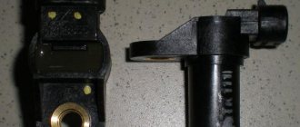
Where is the DTOZH of the VAZ 2123 engine?
The coolant temperature sensor is an electrical resistor with a built-in thermometer. The device is called a thermistor. The principle of operation is simple: when the temperature changes, the resistance changes, which affects the executive part of the system. To measure the thermistor, use a multimeter set to resistance.
Connection diagram of the VAZ-21214 engine management system with central fuel injection under US-83 toxicity standards with controller 21214-1411010 (EFI-4 type) on VAZ-21214 vehicles: 1 - “CHECK ENGINE” control lamp; 2 — instrument cluster (fragments); 3 — electric fans of the engine cooling system*;
4 — electric heater of the intake pipe; 5 — air temperature sensor; 6 — absolute pressure sensor; 7 — coolant temperature sensor; 8 — block connected to the throttle position sensor; 9 — central fuel injection unit; 10 — block connected to the idle speed regulator;
11 — block connected to the nozzle; 12 — diagnostic block; 13 - controller; 14 — knock sensor; 15 — speed sensor; 16 — oxygen concentration sensor; 17 - adsorber; 18 — battery; 19 - main relay; 20 — fuse block of the engine control system; 21 — relay for turning on the electric fuel pump;
22 — relay for turning on the electric fan*; 23 — relay for turning on the electric heater of the inlet pipe; 24 — electric heater protection fuse; 25 — starter activation relay; 26 — ignition relay; 27 — main car fuse box (fragment); 28 — spark plugs; 29 — tachometer; 30 — electric fuel pump with fuel level sensor;
31 — ignition module; 32 — crankshaft position sensor; 33 - courtesy light switch, located on the driver's door pillar; 34 — control unit of the automobile anti-theft system**; 35 — status indicator of the car anti-theft system**; A - wire going to plug “50” of the ignition switch;
The order of conditional numbering of plugs in the blocks: a - controller; b — control unit of the automobile anti-theft system; c — indicator of the state of the automobile anti-theft system; g — speed sensor; d — central fuel injection unit; e — electric fuel pump and oxygen concentration sensor; g — ignition module; h - absolute pressure sensor.
Connection diagram of the VAZ-21214 engine management system with distributed fuel injection under Euro-2 toxicity standards with controller 2123-1411020-10 (type MP 7.0) on VAZ-21214 vehicles: 1 - control lamp of the engine management system; 2 — instrument cluster (fragments); 3 — electric fans of the engine cooling system;
4 — courtesy light switch, located on the driver’s door pillar; 5 — status indicator of the car anti-theft system; 6 — control unit of the automobile anti-theft system; 7-coolant temperature sensor; 8 — air flow sensor; 9 — throttle assembly; 10 — block connected to the throttle position sensor;
11 — block connected to the idle speed regulator; 12 - controller; 13 — oxygen concentration sensor; 14 — knock sensor; 15 — crankshaft position sensor; 16 — speed sensor; 17 - adsorber; 18 — battery; 19 - main relay; 20 — diagnostic block; 21 — fuse block of the engine control system;
22 — relay for turning on the electric fuel pump; 23 — relay for turning on electric fans; 24 — main car fuse box (fragment); 25 — block connected to the additional wiring harness*; 26 — ignition module; 27 - tachometer; 28 — electric fuel pump with fuel level sensor; 29 — nozzles;
30 — spark plugs; A - rear wiring harness wire connected to switch 4; B - wires connected to plug “1” of fuse block 24 (one wire goes to plug “15” of the ignition switch, and the other to plug “85” of the ignition relay); B - rear wiring harness wires connected to the fuel level indicator.
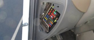
Location of fuses in Niva 21214
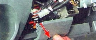
As a rule, the location of the fuses, or fuse mounting block, is located in different places in each car, so you should first find out where the fuse is located. In most cases, the safety block is located under the dashboard, where the dashboard is.
In the Niva-21214 car it is located to the right of the steering wheel, under the panel. When working with the fuse box, you should be careful, as any careless action can damage the fuse box, making subsequent repairs much more expensive.
Electrical equipment of the VAZ 21214 car
Symbols on the diagram
1. Left front light. 2. Headlights. 3. Coolant temperature sensor. 4. Sound signal. 5. Throttle position sensor. 6. Mass air flow sensor. 7. Electromagnetic valve for adsorber purge. 8. Injectors. 9. Right front lamp. 10. Side direction indicators. 11. Rechargeable battery. 12. Electric heater motor. 13. Additional resistor for the heater motor. 14. Differential lock warning lamp switch.15. Windshield wiper relay. 16. Starter 21214. 17. Windshield wiper motor.18. Generator VAZ-21214. 19. Windshield washer motor.20. Ignition module. 21. Spark plugs.22. Controller. 23. Idle speed control. 24. APS status indicator. 25. Temperature indicator sensor.26. Oil pressure warning light sensor. 27. Socket for portable lamp(*). 28. Brake fluid level warning lamp switch. 29. Diagnostic block. 30. Relay for turning on the heated rear window. 31. Headlight high beam relay. 32. Relay for low beam headlights. 33. Electric fuel pump with fuel level sensor. 34. Starter activation relay. 35. Additional fuse block.36. Main fuse block. 37. Relay-breaker for direction indicators and hazard warning lights. 38. Reversing light switch. 39. Brake light switch. 40. Cigarette lighter VAZ-21214. 41. External lighting switch.42. Illumination lamps for heater control levers. 43. Rear fog light switch. 44. Rear window heating switch. 45. Heater motor switch. 46. Rear window wiper and washer switch. 47. Hazard switch. 48. Ignition switch. 49. Instrument lighting switch. 50. Windshield wiper switch. 51. Windshield washer switch. 52. Horn switch. 53. Turn signal switch. 54. Headlight switch. 55. Electric fuel pump relay. 56. Vehicle speed sensor. 57. Lamp switches located in the door pillars. 58. Interior lamps. 59. Rear window washer motor. 60. Instrument cluster. 61. Parking brake warning lamp switch. 62. Main relay. 63. Tail lights. 64. License plate lights. 65. Rear window wiper motor. 66. Rear window heating element. 67. Crankshaft position sensor. 68. Knock sensor. 69. VAZ oxygen sensor. 70. Electric fan relay. 71. Electric fans. 72. Injection system fuse block. 73. To the interior lamp. 74. To the courtesy light switch in the driver's door. 75. APS control unit.
Electrical diagram of VAZ-21214M 2011
ELECTRICAL CONNECTION DIAGRAM FOR FRONT WIRING HARNESS 21214-3724010-44
- 1 – right headlight;
- 2 – starter relay;
- 3 – front harness block to the instrument panel harness block;
- 4 – air temperature sensor;
- 5 – coolant temperature sensor;
- 6 – oil pressure warning lamp sensor;
- 7 – sound signal VAZ-21214;
- 8 – brake fluid level sensor;
- 9 – left headlight;
- 10 – pads for the front harness, sidelight harness and side turn signal
- right;
- 11 – pads for the front windshield wiper motor harness and electric motor;
- 12 – windshield wiper motor;
- 13 – blocks of the front harness and connecting starter wire;
- 14 – starter;
- 15 – rechargeable battery;
- 16 – generator;
- 17 – front harness block and connecting generator wire;
- 18 – right side turn signal;
- 19 – right sidelight;
- 20 – electric motor for washers;
- 21 – pads for the front harness, sidelight harness and side turn signal
- left;
- 22 – left sidelight;
- 23 – left side turn signal.
IGNITION SYSTEM WIRING HARNESS CONNECTION DIAGRAM 21214-3724026-44
- 1 – controller;
- 2 – diagnostic block;
- 3 – mass air flow sensor;
- 4 – coolant temperature sensor;
- 5 – phase sensor;
- 6 – electric fuel pump module;
- 7– block of the instrument panel wiring harness to the block of the rear wiring harness;
- 8 – ignition coils;
- 9 – spark plugs;
- 10 – electronic accelerator pedal;
- 11 – throttle pipe with electric drive;
- 12 – electric fan of the engine cooling system, right;
- 13 – electric fan of the engine cooling system, left;
- 14 – knock sensor;
- 15 – blocks of the wiring harness of the ignition system and the wiring harness of the injectors;
- 16 – VAZ-21214 injectors;
- 17 – solenoid valve for purge of the adsorber;
- 18 – control oxygen sensor;
- 19 – diagnostic oxygen sensor;
- 20 – crankshaft position sensor;
- 21 – APS control unit;
- 22 – APS status indicator;
- 23 – ECM fuse block;
- 24 – fuse for the power supply circuit of the electric fuel pump;
- 25 – electric fuel pump relay;
- 26 – left engine cooling system electric fan relay;
- 27 – relay for the electric fan of the right engine cooling system;
- 28 – ignition relay;
- 29 – ignition system wiring harness block to panel wiring harness block
- devices.
INSTRUMENT PANEL WIRING HARNESS CONNECTION DIAGRAM 21214-3724030-44
- 1 – additional relay;
- 2 – relay-interrupter of direction indicators;
- 3 – windshield wiper relay;
- 4 – ignition switch;
- 5 – alarm switch;
- 6 – rheostat;
- 7 – switch for headlights and direction indicators;
- 8 – windshield wiper and washer switch;
- 9 – main fuse block;
- 10 – additional fuse block;
- 11 – instrument cluster;
- 12 – external lighting switch;
- 13 – rear window wiper switch;
- 14 – rear window heating switch;
- 15 – rear fog light switch;
- 16 – heater motor switch;
- 17 – additional resistor of the heater electric motor;
- 18 – heater electric motor;
- 19 – relay for high beam headlights;
- 20 – low beam headlight relay;
- 21 – rear window heating relay;
- 22 – rear fog light relay;
- 23 – cigarette lighter VAZ-21214;
- 24 – differential engagement sensor;
- 25 – brake signal switch;
- 26 – reverse lamp switch;
- 27 – handbrake warning lamp switch;
- 28 – illuminator;
- 29 – illuminator;
- 30 – instrument panel harness block to the front harness;
- 31 – block of the instrument panel harness to the radio;
- 32 – block of the instrument panel harness to the ignition system harness;
- 33 – instrument panel harness block to the rear harness;
- 34 – indicator lamp for turning on the differential;
- 35 – control lamp for heated rear window;
- 36 – clutch pedal position signal switch;
- 37 – speed sensor.
REAR HARNESS DIAGRAM 21214-3724210-44
- 1 – rear wiring harness block to the instrument panel wiring harness block;
- 2 – rear wiring harness block to the ignition system wiring harness block;
- 3 – switch for the interior lighting in the driver's door pillar;
- 4 – switch for interior lighting in the passenger door pillar;
- 5 – left interior lamp;
- 6 – right interior lamp;
- 7 – electric fuel pump with fuel level indicator sensor;
- 8 – rear window heating element;
- 9 – additional brake signal;
- 10 – right lamp;
- 11 – left lamp VAZ-21214;
- 12 – license plate light;
- 13 – license plate light;
- 14 – electric motor for rear window wiper;
- 15 – rear window washer electric motor.
Engine control system fuses
| F1 (30A) | Right electric fan relay contacts |
| F2 (30A) | Left electric fan relay contacts |
| F3 (15A) | Relay windings of the right and left electric fans, controller, injectors, ignition coil |
| F4 (15A) | Heating elements for control and diagnostic oxygen concentration sensors, phase sensor, mass air flow sensor, canister purge valve |
| №1 | Ignition relay |
| №2 | Main relay |
| №3 | Right cooling fan relay |
| №4 | Left cooling fan relay |
| №5 | Fuel pump relay (fuel) |
| №6 | Fuel pump fuse F5, 15A |
On some vehicle versions, a starter relay may be located under the additional unit next to the ignition relay.
| F1 (30A) | Right electric fan relay contacts |
| F2 (30A) | Left electric fan relay contacts |
| F3 (15A) | Relay windings of the right and left electric fans, controller, injectors, ignition coil |
| F4 (15A) | Heating elements for control and diagnostic oxygen concentration sensors, phase sensor, mass air flow sensor, canister purge valve |
It has already been noted that in the block located in the cabin, some of the fuses are responsible for the operation of the lighting system. Below is a lighting control diagram, as well as a table that explains how the wires are designated.
| Item number | Designation |
| 1 | Front headlight bulbs. |
| 2 | BP. |
| 3 | Outdoor lamps. |
| 4 | Dashboard lighting. |
| 5 | Outdoor lamps. |
| 6 | License plate lamps. |
| 7 | Tail lights. |
| 8 | Reversing lamps. |
Thanks to this scheme, you can find the right element in time if for some reason it fails. For example, when a signal is sent to the power windows, they will begin to move, cleaning the glass.
Also interesting: Niva Chevrolet speed sensor - Auto magazine MyDucato
Dashboard
For subsequent modifications of the VAZ 2121, the instrument panel was thoroughly redesigned. In particular, the design and location of the warning lamps have changed, and new scales have appeared on the instrument panel indicators.
Original wiring diagram for VAZ 21214 – instrument panel and warning lamp harness
All control devices are interconnected. This combination consists in particular of:
- speedometer;
- tachometer;
- coolant temperature indicator;
- 12 indicator lamps;
- battery charge sensor;
- fuel level indicator.
DETAILS: VAZ 2131 Niva: price of VAZ 2131 Niva, technical characteristics of VAZ 2131 Niva, photos, reviews, video
All of them are located on the panel.
The schematic diagram shows the combinations available on the instrument panel:
- tachometer (1);
- stabilizer (2);
- panel illumination (3);
- coolant heating indicator (4);
- gasoline level (5);
- toxicity reduction systems (6);
- heated luggage door glass (7);
- fog lights (8);
- high beam (9);
- outdoor lighting (10);
- turn signals (11);
- TG level (13);
- oil pressure (14);
- differential locks (15);
- fuel reserve (16);
- seat belts (17);
- parking brake (18).
D1, D2 are diodes (type IN4002).
Cars manufactured before 1996 also have a voltmeter (12 in the diagram).
Finally, there are two resistors:
- R1 – at 470 Ohm (0.25 W);
- R2 –51 Ohm, (5 W).
symptoms
The symptomatology of the malfunction has its own characteristics and differs from the burning of an incandescent lamp or damage to the circuit. Thus, if the problem is in the relay, then when turning the switch the driver will see one of the following manifestations:
- The indicator does not light up, the turn signals are off;
- The dashboard indicator and turn signals are constantly on;
- When the relay operates, an uncharacteristic crack (clicks) occurs;
- Within a short time there is a change in the pace of functioning;
- Different response rate compared to alarm.
Stainless steel pants
Now is the time to talk about engine modifications. A new camshaft, manufactured according to LSGA calculations, was installed. Of course, a new gear is also installed along with the shaft for precise adjustment of the valve timing. The controller is also equipped with a proprietary engine control program from LSGA.
Instead of the serial production of the 4-in-1 scheme, a 4-2-1 smoker with long “pants” (they are responsible for the increase in torque) made of stainless steel is installed. In connection with the change in the exhaust system, an extended oxygen sensor cord is also installed. Instead of a standard muffler, there is a so-called silent direct-flow muffler. In addition, the cylinder head passages and valves have been modified.
For example, their locking chamfers are now at an angle of 30 degrees instead of the standard 45, and this at a certain point gives an increase in air flow and, ultimately, good “low-end” to the motor. The environmental issue of Niva LSGA did not remain behind the scenes. For an additional fee, a sports neutralizer is installed in the modified exhaust system.
There is also an economical option - moving the standard neutralizer to a new location. But it is accompanied by a slight loss of power (about 2 hp).
A set of original components for the Niva LSGA - 95. The version with a 105-horsepower engine is complemented by a further modified cylinder head. A set of original components for the Niva LSGA - 95. The version with a 105-horsepower engine is complemented by a further modified cylinder head.
As a result of a full range of modifications, the Niva LSGA engine produces 106 hp. at 5170 rpm.
Maximum torque reaches 163 N.m at 4080 rpm. Moreover, there is an increase in torque in comparison with the serial engine from the very bottom, but the largest makeweight falls precisely in the range of 3200–4800. This is what ensures such pleasant acceleration dynamics of the Niva (read: elasticity of the motor) in higher gears in a speed range where it did not exist before.
| During the modification of the cylinder head, one had to be sacrificed. It was sawn into pieces to study the channels, wall thickness, etc. During the modification of the cylinder head, one had to be sacrificed. It was sawn into pieces to study the channels, wall thickness, etc. | Nowadays it is impossible to imagine competent development without the use of a computer. So with the Niva engine they used a flow simulation program. Now it is impossible to imagine competent development without the use of a computer. So with the Niva engine they used a flow simulation program. |
| External speed characteristics of the modified versions are 105, 95, 90 hp. in comparison with the serial engine. External speed characteristics of the modified versions are 105, 95, 90 hp. in comparison with a serial motor. | Engine power of the Niva LSGA 105 against the background of the serial unit. Engine power of the Niva LSGA 105 against the background of the serial unit. | Power sells well, but torque is more important on the road. Compare the torque curves of the modified and production motor. Characteristics taken at the MAHA stand. Power sells well, but on the road torque is more important. Compare the torque curves of the modified and production motor. Characteristics taken at the MAHA stand. |
We will sequentially go down from top to bottom through the remaining stages of improvements.
Niva LSGA 95 hp — this is the listed set minus the modified cylinder head and valves. LSGA 94 hp — minus direct-flow muffler. LSGA 90 - minus the modified exhaust system.
In this option, all that remains is a new camshaft, a precision phase adjustment gear, the LSGA control program, and adjustment at the MAHA stand.
It remains to be hinted that all the developments for the Chevrolet Niva engine are quite suitable for the Lada 4x4.
Error in the text? Select it with your mouse! And press: Ctrl Enter
Replacing the alternator belt
To change the Chevrolet Niva alternator belt, you need to use the following tools:
In a Chevrolet Niva car, replacing the alternator belt is as follows:
- You need to remove the connector from the crankshaft position sensor.
- Unscrew and remove the bolt that secures the sensor.
- The nut securing the generator needs to be loosened slightly and moved towards the block. If the generator is displaced, its belt will loosen and can be removed without problems.
- Using a jack installed on the side where the generator is located, raise the car by engaging first gear.
- Pull the belt until it moves away from the pump pulley. Rotate the wheel so that the place of the guy moves onto the pulley.
- Then remove the belt from the other pulleys.
- The new one must first be put on the generator pulley and the crankshaft pulley, and only then put on the pump pulley.
- Turn the wheel until the belt is on the pulley.
- Put the generator in place, and tighten the belt, attach it to the bracket with a nut.
- Replace the crankshaft position sensor.
The process of replacing the alternator belt is complete.
Chevrolet Niva spare parts stores in Moscow
You can select the part you are interested in for Chevrolet NIVA Chevrolet NIVA cars and order and purchase spare parts in Moscow online, as well as install them in one of our service centers according to the standards of an official dealer
Specify the make, model and VIN number of the car for a more accurate selection of spare parts or select it from the garage.
Indicate the catalog numbers of spare parts or simply write down which spare parts you need in a list, and our specialist will select the correct numbers, check prices and availability.
Pay for your order online or in our offices upon receipt. Pick it up at a car dealership convenient for you in Moscow.
Types of fuses
Over the entire period of its existence, this segment of car elements has changed more than one type. The most common ones are:
Flat fuses are considered a relatively new type. They are used in almost all new cars. They became widespread due to their increased level of reliability and relatively low cost.
The next item will be ceramic fuses, which used to be very popular, but have lost their position due to low efficiency.
The oldest of all types of fuses are glass. They are small cones made of glass. This type of fuses is practically not used today due to the low level of reliability.
These are the most common types of fuses, however, there are others, but less popular.