April 30, 2020 Lada.Online 34 117 8
The fault indicator (Check Engine) on Lada 4×4 cars (VAZ 21214, 21314) is located in the instrument cluster. When the warning light turns on, it signals to the driver that the on-board diagnostic system has detected a malfunction of the ECM and the vehicle continues to move in emergency mode. To determine the cause, you should use a diagnostic tool, with which you can read error codes and decipher them according to the table below.
To carry out repair and maintenance work on the vehicle's engine management system, a diagnostic tool should be used. In service centers this can be a DST; for self-diagnosis, an ELM327 OBD-II scanner (price about 200 rubles, see the AliExpress catalog) and a smartphone with installed software (for example, OpenDiag), or an on-board computer installed in the car, are suitable for self-diagnosis.
Diagnostic codes of the ME17.9.7 controller
:
| Code | Description |
| P0030 | DC heater to neutralizer, circuit faulty |
| P0031 | DC heater before the neutralizer, control circuit shorted to ground |
| P0032 | DC heater before the neutralizer, control circuit closed to the on-board network |
| P0036 | DC heater after the neutralizer, the circuit is faulty |
| P0037 | DC heater after the neutralizer, control circuit short to ground |
| P0038 | DC heater after the neutralizer, control circuit closed to the on-board network |
| P0101 | Mass air flow sensor circuit, signal output from permissible range |
| P0102 | Mass Air Flow Sensor Circuit Low Signal |
| P0103 | Mass Air Flow Sensor Circuit High Signal |
| P0112 | Intake Air Temperature Sensor Circuit Low Signal |
| P0113 | Intake Air Temperature Sensor Circuit High Signal |
| P0116 | DTOZH circuit, signal output from permissible range |
| P0117 | DTOZH circuit, low signal level |
| P0118 | DTOZH circuit, high signal level |
| P0122 | TPS circuit A, low signal level |
| P0123 | TPS circuit A, high signal level |
| P0130 | The oxygen sensor before the converter is faulty |
| P0131 | DC circuit to the neutralizer, low output signal level |
| P0132 | DC circuit to the neutralizer, high output signal level |
| P0133 | DC circuit to the neutralizer, slow response to changes in mixture composition |
| P0134 | The oxygen sensor circuit to the converter is inactive |
| P0135 | Oxygen sensor to converter, heater faulty |
| P0136 | The oxygen sensor after the converter is faulty |
| P0137 | DC circuit after the neutralizer, low signal level |
| P0138 | DC circuit after the neutralizer, high signal level |
| P0140 | The oxygen sensor circuit after the converter is inactive |
| P0141 | Oxygen sensor after converter, heater faulty |
| P0171 | Fuel system too lean |
| P0172 | Fuel system too rich |
| P0201 | Cylinder 1 injector, circuit faulty |
| P0202 | Cylinder 2 injector, circuit faulty |
| P0203 | Cylinder 3 injector, circuit faulty |
| P0204 | Cylinder 4 injector, circuit faulty |
| P0217 | Engine temperature is higher than permissible |
| P0222 | TPS B circuit, low signal level |
| P0223 | TPS circuit B, high signal level |
| P0261 | Cylinder 1 injector, control circuit short to ground |
| P0262 | Cylinder 1 injector, control circuit shorted to on-board power supply |
| P0264 | Cylinder 2 injector, control circuit short to ground |
| P0265 | Cylinder 2 injector, control circuit shorted to on-board power supply |
| P0267 | Cylinder 3 injector control circuit short to ground |
| P0268 | Cylinder 3 injector, control circuit shorted to on-board power supply |
| P0270 | Cylinder 4 injector control circuit short to ground |
| P0271 | Cylinder 4 injector, control circuit shorted to on-board power supply |
| P0300 | Random/multiple misfires detected |
| P0301 | Cylinder 1, misfire detected |
| P0302 | Cylinder 2, misfire detected |
| P0303 | Cylinder 3, misfire detected |
| P0304 | Cylinder 4, misfire detected |
| P0327 | Knock Sensor Circuit Low Signal |
| P0335 | Crankshaft position sensor circuit is faulty |
| P0340 | Phase sensor is faulty |
| P0351 | Ignition coil of cylinder 1 (1-4), control circuit open |
| P0352 | Ignition coil of cylinder 2 (2-3), control circuit open |
| P0353 | Ignition coil of cylinder 3, control circuit breakage |
| P0354 | Ignition coil of cylinder 4, control circuit breakage |
| P0363 | Misfires detected, fuel supply to idle cylinders turned off |
| P0422 | Neutralizer efficiency below threshold |
| P0441 | Gasoline vapor recovery system, incorrect air flow through the control unit |
| P0444 | Canister purge valve, control circuit open |
| P0458 | Canister purge valve, control circuit short to ground |
| P0459 | Canister purge valve, control circuit shorted to on-board network |
| P0480 | Fan relay 1, control circuit open |
| P0481 | Fan Relay 2, Control Circuit Open |
| P0485 | Fan supply voltage is out of range |
| P0500 | Vehicle speed sensor is faulty |
| P0501 | Vehicle speed sensor, signal out of acceptable range |
| P0504 | Brake pedal A/B switches, signal mismatch |
| P0560 | Vehicle on-board voltage |
| P0561 | On-board voltage is unstable |
| P0562 | On-board voltage, low level |
| P0563 | On-board voltage, high level |
| P0606 | Court controller, ADC malfunction |
| P0615 | Add. starter relay, control circuit open |
| P0616 | Add. starter relay, control circuit short to ground |
| P0617 | Doi. starter relay, control circuit shorted to on-board network |
| P0627 | Fuel pump relay, control circuit open |
| P0628 | Fuel pump relay, control circuit short to ground |
| P0629 | Fuel pump relay, control circuit shorted to on-board network |
| P0645 | A/C compressor clutch relay, control circuit open |
| P0646 | A/C compressor clutch relay, control circuit short to ground |
| P0647 | Air conditioning compressor clutch relay, control circuit shorted to on-board network |
| P0691 | Fan Relay 1 Control Circuit Short to Ground |
| P0692 | Fan relay 1, control circuit shorted to on-board power supply |
| P0693 | Fan Relay 2 Control Circuit Short to Ground |
| P0694 | Fan relay 2, control circuit shorted to on-board power supply |
| P0830 | Clutch pedal switch, circuit faulty |
| P1335 | Throttle Actuator Control Monitoring, Throttle Position Out of Range |
| P1336 | Monitoring the control of the throttle valve drive, mismatch of signals from sensors “A” / “B” of the throttle position |
| P1388 | Monitoring the control of the throttle valve drive, mismatch of signals from sensors “A” / “B” of the accelerator pedal position |
| P1389 | Throttle actuator control monitoring, engine speed out of range |
| P1390 | Monitoring of throttle actuator control, incorrect response to a malfunction in the system |
| P1391 | Monitoring throttle actuator control, no response to system malfunction |
| P1545 | Throttle valve actuator, throttle position out of range |
| P1558 | Throttle valve actuator, return spring faulty |
| P1559 | Throttle valve actuator, throttle position at rest is outside the permissible range |
| P1564 | Throttle valve drive control system, throttle zero position adaptation interrupted due to low voltage |
| P1570 | Immobilizer, circuit faulty |
| P1578 | Throttle valve actuator control system, zero position adaptation value is out of range |
| P1579 | Throttle valve control system, throttle zero position adaptation interrupted due to external conditions |
| P1602 | Court controller, power supply loss |
| P1603 | Throttle actuator control monitoring, monitoring module malfunction |
| P2100 | Electric throttle actuator, control circuit open |
| P2101 | Electric throttle actuator, control circuit faulty |
| P2122 | Pedal Position Sensor A Circuit Low |
| P2123 | Pedal Position Sensor A Circuit High |
| P2127 | Pedal Position Sensor B Circuit Low |
| P2128 | Pedal Position Sensor B Circuit High |
| P2135 | Sensors “A” / “B” throttle position, signal mismatch |
| P2138 | Accelerator pedal position sensors “A” / “B”, signal mismatch |
| P2176 | Throttle valve control system, throttle zero position adaptation not performed |
| P2187 | Fuel system too lean at idle |
| P2188 | Fuel system too rich at idle |
| P2301 | Ignition coil of cylinder 1 (1-4), short circuit of the control circuit to the on-board network |
| P2304 | Ignition coil of cylinder 2 (2-3), short circuit of the control circuit to the on-board network |
| P2307 | Ignition coil of cylinder 3, short circuit of the control circuit to the on-board network |
| P2310 | Ignition coil of cylinder 4, control circuit shorted to on-board network |
For more details on each variator fault code, ask in the comments.
, we will try to answer you in more detail.
Why did the light come on and how to fix it
The main situations in which the indicator lights up and the recommended courses of action for the car owner:
- If the Check engine lights up and goes out immediately when starting the car, there is no damage to the engine. The cause of the fire is most likely harmless - the fuel tank cap is lost or not screwed in properly. Just wrap it tightly and check if the warning disappears.
- If the indicator lights up while driving, you should stop and check the wires. You may find a cable hanging loose under the hood or an open battery terminal. This applies to all attachments - wires, hoses, etc.
- If the light flashes while driving, you should stop and check the sounds made by the engine, pay attention to the oil level, and inspect the sides of the engine. If no visually obvious violations are detected, it is recommended to drive to the nearest car service center and carry out diagnostics.
- If the engine is running normally and the Check light is constantly flashing, there is most likely an ignition failure. You should check the spark plugs and coil, pay attention to the quality of the fuel. To do this, it is better to contact the nearest auto diagnostic center.
- If the indicator is constantly on, you need to stop, unscrew the spark plugs and check the gap. Gaps that exceed 1.3 may cause the light bulb to burn out.
- In addition, when the “check” is on, the ignition is usually checked. Any car service center has special testers that allow you to determine the wear of wiring insulation.
- A faulty fuel pump can also cause the light to come on. You should stop and listen to the sounds the fuel pump makes. A smooth hum without clicks or pauses is considered normal. If extraneous sounds appear, the pump should be dismantled, washed inside and the filter cleaned.
- Serious engine malfunctions can be indicated by the coolant temperature. If it is above 85–90 degrees, and the Check engine lights up while driving, the engine is definitely faulty. In this case, it is advisable to call a tow truck or drive at low speed to the nearest car service center.
Lambda probe Shnivy: device and principle of operation
The essence of the device’s operation lies in changing the resistance of sensors mounted before and after the catalyst. The operating principle of the device is as follows.
- The on-board computer sends a constant electrical pulse at a level of 450 mV to the element.
- If oxygen is present in the escaping gases, a potential difference occurs.
- Depending on the level of gas concentration in the system, the device readings vary from 50 to 900 mV.
- The on-board computer reads the data difference and adjusts the fuel mixture.
Typically, only 1 element is installed on Euro 4 level cars. For EURO 5, the manufacturer already installs two sensors.
Diagnosis of errors on Hyundai Solaris
If the CHECK light comes on when you start the engine, then there is no need to worry. But if the check light is on when the engine has already started, then you need to find out the cause of the error.
The vehicle owner may need to diagnose and remove errors that occur on the Hyundai Solaris in various situations when there is no desire to do this work in a certified service center.
It is not difficult to do this work, the main thing is to know that you can delete errors related to the first level yourself, that is, those that are not recorded in the ECU memory and do not significantly affect the operation of the car and its devices. Because only a special dealer device (scanner - approx.) can remove such errors, one of these errors includes the error of the car's airbags.
Diagnostics using third-party equipment
More precisely, errors on Chevy Niva can be identified by connecting additional equipment. The technique is more technically complex, but allows us to determine the cause of a breakdown or failure with minimal error. In this case, the sequence of actions is as follows:
If all actions are performed correctly, all available information and any errors in the form of encrypted codes will be displayed in the desktop window.
There are also specialized scanners designed specifically for Chevrolet NIVA. Dealer devices are connected to the place of the standard signaling unit through an output cable.
Separately, we should highlight modern devices designed to connect a smartphone to a car, while reading encodings and controlling operating modes occurs directly from the gadget’s display.
At the same time, you should know what the encodings displayed during diagnostics mean. The code consists of several elements.
The next element is a single digit:
The following digit determines the exact serial number of the line in which the defect was detected:
Car exhaust catalyst
An automobile catalyst helps a car make engine exhaust gases more environmentally friendly. It converts carbon monoxide and other harmful substances into harmless compounds. If your exhaust catalyst has become unusable, you will notice it not only when the engine icon (check) appears, but also long before that, when the car’s power drops by half. For example, when you press the gas pedal, the car will not have good acceleration dynamics as before.
What can cause a car catalyst to fail: if you regularly service your car in accordance with the car company's maintenance regulations, then the catalyst should not fail. The main reason for catalyst failure is untimely replacement of a faulty oxygen sensor, as well as non-regular replacement of spark plugs when their expiration date expires.
What needs to be done: If your catalyst has become unusable, then you cannot drive a car, since the engine will not work correctly, warning about this by an indication on the dashboard with an engine icon (check). Also, your fuel consumption will be greatly increased, and there will be no engine thrust.
Although replacing a catalyst is a very expensive repair, there is no escape from repairs. Although there is an alternative to replacing the catalyst with a flame arrester, this is not a 100 percent option. Unfortunately, if you are not an experienced auto mechanic, you will not be able to replace a faulty exhaust gas catalyst yourself.
Characteristics and features of replacing regulators
On products of the domestic automotive industry such as UAZ and Niva, various sensors are needed to transmit information to the dashboard. Also, some of them perform additional functions. And each has its own characteristics of dismantling and installation.
Detonation
The phenomenon of detonation is the explosive combustion of fuel in an engine due to glow ignition. SUVs like the Niva suffer from this problem quite often.
A piezoceramic element is installed in the area of the cylinder block - this is the knock sensor. Its function is to transmit a signal to the controller, which will automatically adjust the ignition timing. Thanks to this, the phenomenon will be eliminated. Also, thanks to the sensor, the controller provides a light indication of an emergency situation on the instrument panel.
The Niva knock sensor can be removed using only a screwdriver and a 13mm wrench. Remove the block by pressing the lock, then unscrew the bolt with a wrench.
Camshaft
This part is required to determine the angular position of the timing mechanism in accordance with the crankshaft. Information from it enters the engine control system. It is used to regulate fuel injection and ignition.
Experts recommend changing this part every 100 thousand km or 5 years. This is due to the fact that it is subject to constant temperature changes, which negatively affects the operation of the sensor. Unfortunately, it is quite difficult to independently determine its malfunction; this requires an oscilloscope and other equipment.
Speeds
The Niva 21214 has an electronic, also known as cableless, speed sensor. Its main function is to transmit information about the vehicle speed to the speedometer. You will find this parameter finder on the gearbox, on the rear transfer case cover.
To replace it, you will need to get to the car from below, using a hole or other method.
- Squeeze out the plastic clip and remove the terminal with wires.
- Then use a wrench to unscrew the device. If it doesn't come off, there's no need to pull. The problem is corrosion; WD-40 solvent will help to cope with it; you need to apply it to the connection and wait.
- Install the new part in the reverse order.
Idle move
The idle speed sensor, also known as the regulator (IAC), is located on the throttle valve.
- A block with wires is connected to it, which is removed by releasing the latch. Then you need to unscrew the two bolts using a Phillips screwdriver.
- Then you can simply pull out the sensor.
- When installing, perform the same steps in reverse order.
Fuel level
This sensor is required to display information about how much gas you have left. In some cases, it becomes unusable and needs to be replaced.
First, you'll need to remove the floor mats and rear seat to gain access to the hatch where the gas tank is hidden. The hatch is a sheet secured with 12 screws. Unscrew them and remove the hatch completely by lifting it up and sliding it forward.
Now you can see the gas tank and fuel pump. Remove the connector from the latter by placing a rag under the draining gasoline. It is better to dismantle by draining 5-7 liters from the tank if it is full.
Lada 4×4 3d › logbook › the “check” light periodically lights up in the field 21214
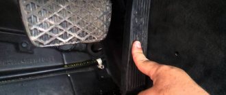
Returning to the previous entry about the incomprehensible situation with the engine or brake pedal sensor... The burning “check engine” icon today, 08/20/2020, finally got to me and I decided to go for computer diagnostics of the car, check the Niva’s brains for possible errors. Previously, I drove around with my brother-in-law in his car those auto shops that I didn’t have time to visit in my Niva.
The new model brake pedal sensor I needed for the VAZ 21214 was not there either - all the sellers looked in amazement at the faulty sensor I was demonstrating, which I took with me, and unanimously turned their heads in different directions, saying the word “No”. Particularly advanced sellers, looking at the markings of the sensor, sent me to the foreign cars department, and my words that this sensor is being installed en masse on all domestic cars with an electronic gas pedal produced in 2021 were perceived with extreme distrust.
It seems like a sensor, like a sensor, if you believe the Internet, then it is produced by a plant in Arzamas, the sensor is marked 8200168238-B, on the other side there is an inscription in English “Renault 047”. On the official website in the city of Togliatti, its cost is set at 170 rubles. In Podolsk, they tried to sell me a sensor with the same marking, but made in Spain or France, for a minimum of 2200 and a maximum of 2900 rubles.
Everything is the same, only on expensive sensors there is additionally the inscription “Made in Spain” (the inscription is made in English). Having returned home, I got into my Niva and went to a car service center for diagnostics. My guess about the malfunction of the brake light switch off sensor or the simple “frog” turned out to be correct.
Also interesting: Niva and Chevrolet Niva Tuning Shop from 10:00 to 18:00
Having previously visited almost all the auto shops in my city in vain, I purchased the brake pedal sensor I needed at a car service center for just the negligible price of 350! rubles The “not original” sensor, completely black, made in France, is installed on some Renault cars. But then the most interesting thing began - the Niva’s engine worked intermittently, and continued to work.
The diagnostician constantly got errors “faulty injectors 1-2” and “misfire in cylinder 1.” During two hours of being in the service center, the spark plugs, the first and second injectors, spark plug wires, compression in all cylinders, and the ignition coil were checked for serviceability. I bought new ones with return conditions - an injector, an ignition coil, DENSO spark plugs (recommended at a car service center).
The spark plugs were original and they were black from carbon deposits. I must say that the electrician-diagnostician found it difficult to determine the malfunction of my car, because... The “misfire in cylinder 1” error appeared constantly, but periodically and disappeared when the engine was restarted. “DENSO” spark plugs were installed on my Niva, and the injector and ignition coil were returned to the seller.
Afterwards, the electrician went to “call a friend” in a nearby repair bay to get advice from other repairmen. In the next box there was a VAZ 2109 with similar symptoms, but with the error “misfire in the 3rd cylinder.” In total, I was told that my fault could not be detected (everything is normal) and they advised me to change the gas station where I constantly fill up my Niva .
I already own my third car, since 2006 I have refueled at only one, the only gas station in Podolsk, and I have never had problems with the engines of my cars. Although everything in our life always happens for the first time. At a car service center, I was advised to completely drain the gasoline from the gas tank and refuel at another gas station, drive around, look, and if the “CHECK” lights up again, then go for warranty repairs to the car dealership where I bought the car.
I just recently filled the tank full. Now there is 0.75 gasoline in the tank. I’m thinking about either pouring my gasoline into a canister, or driving around to produce gasoline, not paying attention to the burning “CHECK”... In terms of money: for two hours of work they charged me “divinely” 1,000 rubles, DENSO spark plugs 700 rubles, diagnostics with removal of the “CHECK” error 500 rubles. Total - 2200 rubles.
Replacing brushes or the generator itself
Current collection brushes wear out most often, so here is a description of how to do this job:
- Remove the negative terminal from the battery and disconnect the wires leading from the generator casing.
- Remove the protective cap from the terminals of the positive terminal of the wires. Unscrew the nut that secures the block to the generator block.
- Disconnect the spring clips and remove the black plastic cover.
- Unscrew the voltage regulator mountings with a Phillips screwdriver. Take it out along with the brushes.
- Disconnect the wires from it. Remove the assembly together with the fastening bar, take off the belt.
- Release the generator from the bracket by unscrewing all the mounting bolts.
Purpose of the button
The instrument panel in a car is a way for the driver to monitor the level of gasoline, oil, engine operating condition or other components of the car, which guarantee comfortable and silent driving on the road.
Modern cars are equipped with an indicator necessary for the convenience and comfort of the driver. If earlier an engine malfunction had to be found only visually or by carefully listening to the operation, today a special light bulb works. It is created for the convenience of monitoring the engine condition. Ideally, it should light up only when the engine starts and go out after a couple of seconds.
If the light does not go out or lights up while driving, then you should think about malfunctions in the operation of the main component of the car.
Wiring diagram VAZ 2131 Niva injector
The Chevrolet Niva lambda probe, together with a sensor system, helps to properly regulate engine operation and use fuel extremely efficiently. This affects the amount of harmful emissions into the atmosphere.
On the Shnivy, the sensor is designed to transmit information to the computer regarding the amount of air coming out after combustion of the fuel. The information helps to adjust the composition of the fuel mixture and unlock the potential of the engine. It also significantly increases the life of the catalytic converter.
Table: reasons for the check engine light to come on and suggested actions
| When and in what cases does the “check” light come on? | Possible reasons | Suggested Actions |
| When driving, when accelerating | Harsh acceleration, faulty air filter | Replace filter, accelerate smoother |
| When the indicator flashes, the engine starts | The fuel in one of the cylinders does not burn completely; the gasoline either burns out in the exhaust pipe or immediately enters the catalyst | Replace spark plugs, check coil and armored wires, check timing marks |
| After refueling | Low fuel quality | Change gas station |
| When the ignition is turned on | Normal car reaction | Nothing should be done |
| After washing the car, engine, after rain | Water got into the Check engine wiring | Treat with WD40, dry, clean contacts |
| Cold | Knock sensor faulty | Replace |
| On a hot engine | Camshaft sensor faulty | Replace |
| At high speeds | Missing ignition coils or faulty crankshaft sensor | Replace coil or sensor |
| At idle | Throttle sensor malfunction | Replace |
| After replacing spark plugs | “Poor” combustible mixture | Change the octane number of gasoline to a higher one |
| After replacing the air filter | More air began to flow, the composition of the exhaust changed, the lambda probe reacted | Turn off the engine and start again |
| After replacing the timing belt | A terminal has come off from some sensor, most likely the air hose | Check terminals |
| After installing gas equipment | Fuel injector emulation is done incorrectly | Tune |
| After installing the alarm | Only one power line is connected to the turbo timer, the second one contains a temperature sensor, brake pedal and mass air flow sensor | Reset Check engine, connect both lines |
| After replacing the fuel filter | Low pressure filter installed | Replace filter |
| With a simultaneous increase in fuel consumption | Driving too long, oxygen heating up or poor quality fuel | Refuel with high-quality fuel and give the car a rest |
| On long climbs | Worn timing belt, faulty sensors | Check and replace |
| After replacing the ignition module | Module connection problems | Remove and reconnect the positive terminal from the battery |
| At sub-zero temperatures | Malfunction of the throttle position sensor or disconnection of its chip | Replace the device or replace the chip |
| When you press the accelerator pedal | Air filter clogged | Clean or replace the filter |
Also interesting: Where is the Chevrolet Niva starter relay located?
content .. 119 120 121 122 123 124 125Niva VAZ-21214.
Operation of the central fuel injection system GENERAL INFORMATION
The amount of fuel supplied by the injector is regulated by an electrical pulse signal from the controller (electronic control unit).
It monitors engine condition data, calculates fuel demand and determines the required duration of fuel supply from the injector (pulse duration). To increase the amount of fuel supplied, the pulse duration increases, and to reduce the fuel supply, it decreases. The controller has the ability to evaluate the results of its calculations and commands, as well as remember the experience of recent work and act in accordance with it. “Self-learning” of the controller is a continuous process that continues throughout the entire life of the vehicle. Typically, one pulse is supplied to the injector per one reference pulse from the crankshaft position sensor. Fuel is supplied either synchronously with the reference pulses, or asynchronously, i.e. without coincidence with them in time. Synchronous fuel injection is the most common fuel supply method. Asynchronous fuel injection is used when additional fuel is needed when the throttle is opened sharply, as indicated by the throttle position sensor. This fuel injection is similar to the carburetor's accelerator pump delivering fuel when the throttle is opened suddenly. Regardless of the injection method, fuel supply is determined by the condition of the engine, i.e. its mode of operation. These modes are provided by the controller and are described below. Engine start mode
When the ignition is turned on, the controller turns on the electric fuel pump relay for 2 seconds, and it creates pressure in the fuel supply line to the central injection unit.
The controller takes readings from the coolant temperature and throttle position sensors and determines the correct air/fuel ratio for starting. After the crankshaft begins to rotate, the controller will operate in starting mode until the speed exceeds 420 rpm, otherwise it may switch to the engine “purge” mode. The duration of each pulse to the injector during startup is 4–6 ms, depending on the coolant temperature and throttle position. Engine Purge Mode
If the engine is “flooded” with fuel, it can be started by opening the throttle valve fully while cranking the crankshaft.
In this mode, the controller sends pulses to the injector corresponding to an air/fuel ratio of 26:1 (pulse duration about 2 ms), which “cleans” the flooded engine. The controller maintains the specified pulse duration as long as the engine speed is below 420 rpm and the throttle position sensor indicates that it is almost fully open (more than 85%). If the throttle is held almost fully open while attempting to start a dry engine normally, the engine may not start because the air/fuel ratio of 26:1 may not be sufficient to start a dry engine, especially if it is not warmed up. Open loop mode after starting (without feedback)
After starting the engine (when the speed is more than 420 rpm), the controller will control the fuel supply system in the “open loop” mode.
In this mode, the controller ignores the signal from the oxygen sensor and calculates the pulse duration to the injector using signals from the crankshaft position sensor (rotation speed information), absolute air pressure sensor, coolant temperature sensor and throttle position sensor. In open cycle mode, the calculated injection pulse duration may result in an air/fuel ratio other than 14.7:1. An example would be the unheated state of the engine, because however, a rich mixture is required to ensure good driving performance. The system will remain in open cycle mode until all of the following conditions are met: – the oxygen sensor signal changes to indicate that it is warm enough to operate normally; – coolant temperature is more than 32° C; – the engine has operated for a certain period of time since starting. The time can vary from 6 s to 5 min depending on the temperature of the coolant at the time the engine starts. If the temperature was below 18° C, the period is 5 minutes. If the temperature was above 75° C, the delay is 6 s. Closed-loop mode after start-up (with feedback)
In closed-loop mode, the controller first calculates the pulse duration to the injector based on signals from the same sensors as in open-loop mode.
The difference is that in closed-loop mode, the controller still uses the signal from the oxygen sensor to adjust and fine-tune the calculated pulse to accurately maintain the air/fuel ratio at 14.6-14.7:1. This allows the catalytic converter to operate at maximum efficiency. Rich Acceleration Mode
The controller monitors sudden changes in throttle position (via the throttle position sensor) and intake manifold pressure (via the absolute pressure sensor) and provides additional fuel by increasing the pulse duration to the injector.
If the increased fuel demand is too great due to a sharp opening of the throttle valve, the controller can add asynchronous pulses to the injector in the intervals between synchronous ones, which during normal operation there is one for each reference pulse from the crankshaft position sensor. Power Boost Mode
The controller monitors the throttle position sensor signal and engine speed to determine when the driver needs maximum engine power.
To achieve maximum power, a rich fuel mixture is required, and the controller changes the air/fuel ratio to approximately 12:1. In this mode, the signal from the oxygen concentration sensor is ignored, because it will indicate the richness of the mixture. Lean Brake Mode
Braking a vehicle with the throttle closed may increase emissions of toxic components.
To prevent this, the controller monitors the decrease in the throttle opening angle and the pressure in the intake pipe and promptly reduces the amount of fuel supplied by reducing the injection pulse. Fuel cut-off mode during engine braking
When engine braking with the gear and clutch engaged, the controller can completely turn off fuel injection pulses for short periods of time.
The fuel supply is turned off when all the following conditions are met: – the coolant temperature is above 44° C; – crankshaft rotation speed above 3150 rpm; – vehicle speed above 42 km/h; – the throttle valve is closed; – the signal from the absolute pressure sensor indicates the absence of engine load (pressure less than 24 kPa); – a table embedded in the permanent memory of the controller and comparing the crankshaft speed with the vehicle speed determines the engaged gear of the gearbox. When the vehicle is braking by the engine, any of the following conditions will cause the fuel injection pulses to resume: – crankshaft speed below 2100 rpm; – vehicle speed is less than 42 km/h; – the throttle valve is open at least 2%; – the signal from the absolute pressure sensor in the intake pipe indicates the presence of load (pressure more than 25 kPa); – the clutch is disengaged. This can be determined by a rapid drop in engine speed. Compensation for power supply voltage drop
When the supply voltage drops, the ignition system may produce a weak spark, and the mechanical “opening” movement of the injector may take longer.
The controller compensates for this by increasing the accumulation time of the current in the ignition coil when the supply voltage drops below 12 V, and when the voltage drops below 8 V - by increasing the idle speed and the duration of the injection pulse. Fuel supply cut-off mode
When the ignition is turned off, the injector does not supply fuel, which prevents self-ignition of the mixture when the engine is overheated.
In addition, fuel injection pulses are not issued if the controller does not receive crankshaft position reference signals, i.e. this means the engine is not running. The fuel supply is also cut off when the maximum permissible engine speed of 6500 rpm is exceeded. The injection pulses will resume after the crankshaft speed drops below 5850 rpm. Diagnostics of the injection system GENERAL INFORMATION
Here we provide only brief information on diagnosing the injection system using the “CHECK ENGINE” warning lamp.
Diagnostics using special instruments and diagnostic cards is described in detail in a separate Repair Manual for the central fuel injection system. The controller continuously performs self-diagnosis on certain control functions. The controller's language for indicating the source of a malfunction is diagnostic codes. Codes are two-digit numbers ranging from 12 to 61. For different controllers, fault codes may differ slightly from each other. The table shows the breakdown of controller fault codes for a central fuel injection system with imported components. When a malfunction is detected by the controller, the code is stored in memory and the “CHECK ENGINE” indicator light turns on. This does not mean that the engine should be stopped immediately, but the reason for the warning light to come on should be discovered as soon as possible. Controller fault codes 12
| Indicator lamp diagnostic circuit fault | |
| 13 | There is no signal from the oxygen concentration sensor |
| 14 | Coolant temperature sensor signal low |
| 15 | High signal level of the coolant temperature sensor |
| 21 | Throttle position sensor signal voltage too high |
| 22 | Insufficient throttle position sensor signal voltage |
| 23 | Excessive signal voltage from the air temperature sensor |
| 24 | There is no signal from the vehicle speed sensor |
| 25 | Insufficient signal voltage from the air temperature sensor |
| 33 | Excessive signal voltage from the absolute air pressure sensor |
| 34 | Insufficient signal voltage from the absolute air pressure sensor |
| 35 | Idle speed deviation |
| 42 | Ignition control circuit malfunction |
| 44 | Lean mixture composition |
| 45 | Enriched mixture composition |
| 51 | Programmable read only memory (PROM) error |
| 53 | System supply voltage too high |
| 54 | Excessive or insufficient octane correction signal voltage |
| 55 | Controller error |
VAZ-21214. "CHECK-ENGINE" lamp
The lamp is located in the instrument cluster and performs the following functions: – informs the driver that there is a malfunction in the engine management system and the car needs to be checked as quickly as possible;
– issues diagnostic codes stored in the controller’s memory to help a specialist find a malfunction. When the ignition is turned on, the lamp lights up and, while the engine is not running, the lamp and systems are checked for serviceability. After starting the engine, the lamp should go out. If the lamp continues to light, then the self-diagnosis system has detected a malfunction. If the fault disappears, the lamp usually goes out after 10 seconds, but the fault code will be stored in the controller’s memory. In the case of an “intermittent” malfunction, the “CHECK ENGINE” lamp will light for about 10 s and then go out. However, the corresponding fault code will be stored in the controller's memory until its power is turned off. When unexpected codes are found during the code reading process, it can be assumed that these codes are caused by an intermittent fault and can help diagnose the system. Reading codes Diagnostic block
| A – contact connected to ground; B – diagnostic contact for sending a signal to the controller; G – electric fuel pump control contact; M – information output contact (serial data channel) |
A diagnostic block is used to communicate with the controller. It is located under the glove compartment on the right side next to the controller. Fault codes stored in the controller's memory can be read either with a special diagnostic tool or by counting the number of flashes of the "CHECK ENGINE" lamp. Issuance of code 12 by the “CHECK ENGINE” indicator lamp
| A – contact connected to ground; B – diagnostic contact for sending a signal to the controller; G – electric fuel pump control contact; M – information output contact (serial data channel) |
To read the codes with a lamp, you must connect contact “B” of the diagnostic block to ground. The easiest way is to short it to ground by connecting it to contact “A”, which is connected to engine ground. When contacts “A” and “B” are connected to each other, the key in the ignition switch must be turned to position III (Ignition), but the engine should not run. Under these conditions, the “CHECK ENGINE” lamp should flash code 12 three times in a row. This should happen in this order: flash, pause (1-2 s), flash, flash - long pause (2-3 s), and so on twice. Code 12 indicates that the controller diagnostic system is working. If code 12 is not displayed, then there is a problem with the diagnostic system itself. After code 12 is displayed, the CHECK ENGINE lamp displays fault codes three times, if they exist, or simply continues to display code 12 if there are no fault codes. If more than one fault code is stored in the controller’s memory, they are displayed 3 times each. Warning
Upon completion of the diagnostics, it is allowed to open contacts “A” and “B” of the diagnostic block 15 seconds after turning off the ignition.
9.1.4.
Erasing codes GENERAL INFORMATION
Erase codes from the controller's memory either after completing repairs or to see if the malfunction occurs again.
To erase, you must turn off the controller's power for at least 10 seconds. Power can be turned off either by disconnecting the cable from the negative terminal of the battery, or by removing the controller protection fuse from the fuse box. Warning
To avoid damaging the controller, turn its power off and on only with the ignition off.
content .. 119 120 121 122 123 124 125
Chevrolet Niva error reset
The standard procedure for resetting the controller occurs only after all faults have been completely corrected, otherwise annoying encryption will appear again. The procedure is performed in two available ways.
- Disconnect the battery from the on-board network for 10-15 minutes. The controller will completely reboot and return to factory default settings.
- In the BC menu, enter the “errors” service, press the daily mileage reset button and wait for the sound signal from the car, and horizontal lines should appear on the display.
Computer diagnostics
The most complete diagnosis is possible with a computer or laptop. In order to use this method, you must purchase an adapter. This adapter performs two functions at once. It is an adapter from a K-line port to a USB port or to a COM port. It also acts as a decoder, which allows you to transmit signals from the ECU to the PC. You will also need to install the appropriate software on your laptop. There are a lot of free versions on the Internet. There are universal programs, as well as programs written for a specific car. After connecting to the computer, you will need to turn on the ignition and launch the program. The connection will happen automatically.
The interface of the computer program is very convenient and allows even an inexperienced user to navigate intuitively. All functionality can be divided into several sections. These are parameters, errors and settings. If the first two sections are informational, then using the third section you can control the vehicle systems.
Few people know that the Chevrolet Niva has a self-diagnosis function that produces basic error codes that can be used to quickly find and fix vehicle problems. It is not difficult to carry out this procedure yourself; just press the odometer button firmly and turn on the ignition at the same time. The arrows on the speedometer will creep up, after pressing again, an information message about the firmware version will be displayed, and the next time, all error codes will appear on the monitor, naturally, if there are malfunctions in the car.
Bottom line
The most common Niva Chevrolet computer errors are found in 90% of car diagnostic cases. There are also a large number of rare failures that are not included in the list due to their low prevalence.
Read news about the new Niva
- The modernized Lada Niva Legend (4x4) 2021 was shown on the Internet
- Lada 4×4 Bronto - sales stopped, new details » Lada.Online - all the most interesting and useful about LADA cars
- Description of the instrument panel Lada 4×4 (VAZ 2121, 2131) » Lada.Online - all the most interesting and useful about LADA cars
- Chevrolet Niva gasoline consumption per 100 km
- Buy LADA (VAZ) 2131 (4×4) 2021 in Rostov-on-Don, low price for Lada 2131 (4×4) 2021 on the Avto.ru website
- Fuses Niva 21214 injector «
- The new large Lada 4×4 Niva “Bigster” 2021-2022 based on the Dacia Bigster was shown for the first time. The SUV has changed beyond recognition
- New Niva Chevrolet Lux 2021 - review of GLC equipment
Self-diagnosis procedure for Chevrolet Niva via OBD2 connector
Determine where the OBD2 connector is located
- From 1990-1994 they are equipped with an OBD1 (GM12) connector - 12 PIN.
- Since 1995, cars have been produced with an OBD2 connector - 16 PIN.
The location of the connector also depends on the type of connector. You can study this issue in the article: “Location of the diagnostic connector on the Chevrolet Niva”
Determine which scanner is suitable for your car
The selection of a scanner (adapter) for a Chevrolet Niva depends on the connector, as well as on the needs of the diagnostician / car owner.
To select diagnostic equipment, use the calculator: “Scanner selection for Chevrolet Niva”
Download the diagnostic program for the scanner
The diagnostic adapter requires software that can be installed on a laptop or smartphone/tablet. Auto scanners with their own software shell and display do not require software.
To select a program for the adapter, go to the section: “Programs”
Use the instructions and carry out diagnostics
When you purchase an adapter, instructions are included with the adapter. More detailed instructions on diagnostic scanners and descriptions of their operation are posted in the section: “OBD2 car scanner reviews”
Identify errors and decipher them
Error codes and their interpretation are displayed in the scanner program interface. You can also study the complete database of errors for your car in the section: “OBD2 error codes for Niva Chevrolet”
Make repairs according to the error code
The unit is repaired according to the decoding of the error (problem) or contact a car service to eliminate a particular malfunction.
Check errors again
How to decipher error codes
If you have ever seen how a VAZ-2114 is diagnosed using special equipment in a service station, you probably noticed that the error code has 4 digits. In our case, during self-diagnosis, the code includes only 2 numeric characters. In general, the codes mean the following:
- if the number 1 appears, it means the microprocessor is malfunctioning;
- 2 – the operation of the sensor circuit indicating the fuel level in the tank leaves much to be desired;
- 4 – there is too high voltage in the electrical circuit;
- 8 – the voltage, on the contrary, is too low, it is not enough for the VAZ-2114 to operate properly;
- 13 – there is no signal from the indicator of available oxygen;
- 14 – high signal value of the coolant temperature indicator, filled in for efficient operation of the car’s cooling system;
- 15 – this signal, on the contrary, is too low;
- 16 – voltage units in the on-board network are off scale;
- 17 – low voltage values of the on-board network;
- 19 – the signal from the locking component regarding the position of the crankshaft is received incorrectly or untimely;
- 24 – the sensor that records the vehicle speed is faulty;
- 41 – the phase sensor signal is received incorrectly;
- 51 – there are problems in the functioning of the operational product responsible for memorization;
- 53 – it’s time to repair the CO potentiometer;
- 61 – lambda probe does not work.
How to replace fuses on a VAZ 21213 (carburetor)?
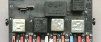
The block is a metal board with flag-type disposable electrical fuses installed in it. A special fuse is provided for each electrical circuit and for all electrical appliances.
Fuse box
An electrical fuse is a low-melting wire core with two mounting legs enclosed in a plastic sheath. The shells are made of plastic of different colors. There is a marking on the top indicating the rating for which the fuse is designed.
In the event of a sudden surge in voltage, the thin wire instantly burns out and the circuit opens, thereby protecting the corresponding equipment from failure.
Video “Replacing fuses on Niva 4x4”
Author Alexander Belousov is looking for the reason for the constant failure of fan fuses on his VAZ 21214.
Niva SUV is known as the VAZ-2121
(VAZ 21213, VAZ 21214) and since 2006 as Lada 4×4
.
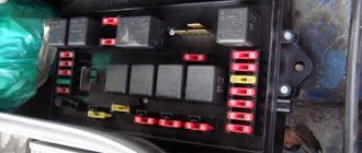
Produced from 1977 to the present with various body modifications, mainly 3- and 5-door station wagons with gasoline engines ( carburetor, injection ). In our publication you will find a description of the fuse and relay blocks of the Niva 2121 with their locations, photo examples of execution and block diagrams. Note the fuse responsible for the cigarette lighter. In conclusion, we will offer a Niva electrical diagram for downloading.
Due to the long production period and the huge variety of designs, there is no one general description of the fuse and relay block for Niva 2121. In your car, the purpose of the fuses may differ from those presented.
All main fuse and relay boxes are located in the passenger compartment, under the instrument panel on the driver's side.
On which cars is this problem most common?
The problem with code P0135 can occur on different machines, but there are always statistics on which brands this error occurs more often. Here is a list of some of them:
- Acura (Acura MDX)
- Alfa Romeo
- Audi (Audi a4, Audi TT)
- BMW
- Chery (Chery Amulet, Tiggo)
- Chevrolet (Chevrolet Aveo, Ventura, Cruz, Lacetti, Tahoe)
- Chrysler (Chrysler Sebring)
- Citroen (Citroen C3, C4, Berlingo)
- Daewoo (Daewoo Matiz, Nexia)
- Daihatsu
- Dodge (Dodge Durango, Caravan, Neon, Stratus)
- Fiat (Fiat Doblo, Ducato, Stilo)
- Ford (Ford Galaxy, Mondeo, Taurus, Focus, Escape)
- Geely
- Honda (Honda Accord, Odyssey, SRV, Stream, Fit, Civic, HR-V)
- Hover
- Hyundai (Hyundai Accent, Santa Fe, Sonata)
- Iveco (Iveco Daily)
- Jeep (Jeep Grand Cherokee)
- Kia (Kia Rio, Sefiya, Sid, Spectra, Sportage, Shuma)
- Lexus (Lexus gs300, lx470, rx300)
- Mazda
- Mercedes
- Mitsubishi (Mitsubishi Airtrek, Outlander, Galant, Grandis, Karizma, Lancer, Pajero, Space Star)
- Nissan (Nissan Qashqai, Maxima, March, Note, Sunny, Tiida, X-Trail)
- Opel (Opel Astra, Vectra, Zafira, Corsa, Omega)
- Peugeot (Peugeot 206, 207, 307, 308, 406, 407, Partner)
- Renault (Renault Duster, Logan, Scenic)
- Skoda (Skoda Octavia)
- Ssangyong (Sanyeng Aktion, Kyron)
- Suzuki (Suzuki Grand Vitara, Liana, Swift)
- Toyota (Toyota Avensis, Ipsum, Kluger, Corolla, Crown, Land Cruiser, Mark 2, Prado, Premium, Harrier, Estima)
- Volkswagen (Volkswagen Golf, Passat)
- Volvo
- VAZ 2105, 2107, 2110, 2112, 2114, 2115
- Gazelle Business, Chrysler
- Zaz Chance
- Lada Kalina, Niva, Priora
- UAZ Patriot
With fault code P0135, you can sometimes encounter other errors. The most common are: P0030, P0107, P0130, P0132, P0134, P0138, P0155, P0161, P0170, P0171, P0174, P0300, P0301, P0302, P0303, P0304, P0314, P0400, P0443, P059 7, P1135, P1409, P2243 .
Replacing oxygen concentration sensors
Oxygen sensors need to be replaced after 75 thousand km of vehicle mileage.
We unscrew the sensors when the engine has cooled down.
Disconnect the negative terminal of the battery.
To replace the control sensor, in the engine compartment, press the lock of the wire block and disconnect it
Disconnect the plastic holder of the sensor wiring harness from the bracket
Use a 22 key to unscrew the sensor.
We remove the sensor from the engine compartment
If the sensor is very stuck and cannot be unscrewed using an open-end wrench, then if you are replacing the sensor, you can cut the sensor wires with side cutters and unscrew them with a spanner.
You can also disassemble the wiring block if the sensor cannot be replaced.
To replace the diagnostic oxygen sensor, pry from the bottom of the car with a screwdriver and disconnect the wire holder from the protective casing of the wire blocks.
Using a 10mm wrench, unscrew the two nuts.
Remove the protective casing with wire blocks
We remove the wire blocks from the protective casing
We press the block clamp, disconnect the wiring harness blocks
Use a 22 key to unscrew the sensor.
Removing the diagnostic sensor
Oxygen concentration sensor
When installing the sensor, do not allow dirt and grease to get on the pads and the sensor itself.
We install the sensors in reverse order.
