Hi all! Summer is approaching and I noticed that they are boiling, overheating, etc. I don’t like that in hot weather when driving not fast, the temperature of the engine coolant on the dashboard rises close to the red zone, after which the cooling system fan starts and the arrow falls down. And so back and forth. In general, for a VAZ 2110 such spasmodic behavior of the needle is considered normal.
Of course, the dashboard may be lying here and according to the On-Board Computer the readings are completely different. But still the effect is unpleasant and always alarming. I would like to somehow make the temperature control smooth and not abrupt. So that the temperature is maintained at the same level all the time due to different rotation speeds of the Carlson or by turning on the fan earlier.
And then the idea occurred to me to make, like many others, a forced button to turn on the fan. After looking on the Internet how this is done, I got to work.
And so, what we need: 1. Copper wire with a cross-section of 1.5-2 mm. (I have a wire about half a meter long) 2. Button (I took the air circulation button.) 3. 2 terminals (male, female) 4. Electrical tape.
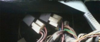
First of all, disconnect the “-” terminal from the battery. Next, we unscrew the cover, which is attached to two or three self-tapping screws, remove the cover and see three relays there.
We need a relay
fan,
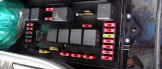
Relay: 1 – electric fan relay; 2 – electric fuel pump relay; 3 – main relay (ignition relay).
ATTENTION! I have the order of the relays from the factory. The order of relays and fuses can be arbitrary, we focus on the color of the wires.
Next, we take the wire and connect contacts 30 and 87 on the fan relay, no matter which wire goes where, the contact numbers are on the relay itself. I have an upper and lower entrance. And we lead the wire to the place where you want to connect the button.
I got it like this:
fan switch button for VAZ 2110
I connected the battery, turned on the button, it works like a clock!
In addition, I made a video.
Thank you all, this is temporary for me and then I will connect it through an additional relay.
Everything is simple and clear, I think you won’t have any questions when connecting, the main thing is not to be lazy and everything will work out for you!
Many people have noticed that the temperature at which the radiator fan on a VAZ turns on is too high when compared with the operating temperature of the engine. Manufacturers are trying to reduce the amount of harmful emissions, since at high temperatures the fuel burns better together with the components.
But there is not only a positive effect, but also a negative one. If the engine overheats a little, then destructive processes begin for the metal inside, so wear resistance decreases. If you do not take into account that electrical components that affect the switched on fan may fail, then the time to notice overheating will be less than at normal temperatures.
We need to ensure that the engine operates evenly. This can be accomplished by creating a parallel fan circuit. A positive wire must be connected to one contact, and the negative contact is connected to the switch via a parallel wire.
It is worth mentioning additional features that allow you to control the normal engine temperature. There are no relays in the electrical circuit as a simple switch is sufficient for operation.
This method is not a replacement for the standard fan operation circuit, but only an alternative option for operating the unit at low temperatures. The driver must control the entire process.
If the car’s engine overheats, but this connection diagram is implemented, then it is better to check the cooling system again, ensuring its operation.
As soon as signs of overheating are detected, that is, the arrow indicating the temperature has entered the red zone, but there is still no puff of steam from the engine compartment, then turn on the interior heater at full power.
This will help reduce the temperature of the coolant in the cooling system. Next you need to turn on the emergency lights, depress the clutch pedal and roll to the side of the road. The car cannot be turned off immediately; the engine is run at normal idle speed for about five minutes, and the heater must still operate at full power. Only now can you open the hood and inspect the engine compartment.
You need to try to determine where the steam is coming from, see if there is coolant in the expansion tank, check the integrity of the thermostat, radiator and rubber hoses.
And so hello everyone. In Volgograd, the heat is terrible, the temperature in the shade is 40 degrees, and in the sun it’s probably 50 degrees, my engine cooling system can’t cope with such climatic conditions, even at speed the temperature doesn’t drop below 90, and in a traffic jam it actually reached almost 120. Start The fan of the engine cooling system (VSOD) is programmed at 105-107 degrees, shuts down somewhere around 100, constant on and off periodically begins to wear on. In connection with this, it was decided to modify the cooling system. There are many options for improvement: 1. Smooth start of the coolant fan 2. Use SILICH-BOREY 3. Start regulator for the RPV fan of LADA cars 4. Turn on the radiator fan (Carlson) from the button. I won’t describe each method, I chose 4 from the button, and I’ll tell you about it. And so we need:
1.relay 4-pin
2. block to the relay (optional)
3. resistance (resistor) of the heater VAZ 2110 3-pin
5. Terminals mother + father (10 pieces)
6.recirculation button VAZ 2110
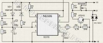
And so everything is ready, we can start. We will use this circuit: The circuit is simple: in parallel with the standard fan relay Rv, an additional relay Rv2 is connected, manually controlled by the button Sv2. When relay Rb2 is turned on, the fan is connected to ground through resistance Rb2, which ensures slow rotation. The standard circuit operates as before; upon a signal from the controller, the fan turns on at full speed.
We are looking for a thin pink-black wire coming from the main relay (pin 85*) and a thick power white-black wire (pin 87) and connect our relay to them. * according to the book, on different VAZ models of the 10th family, the pink-black wire of the main relay can come to both pin 86 and 85. We focus on the color of the wires. We do not touch the black-purple (black-red) thin wire coming from the controller.
Design and testing of the VAZ 2110 fan switch sensor
To maintain optimal temperature conditions of the car engine, a cooling system is designed. Its main elements are channels for antifreeze in the cylinder block, pipes, a thermostat, a radiator, and the electrical part includes a VAZ 2110 fan switch sensor, a temperature sensor and an electric motor with an impeller for cooling the radiator. Late detection of cooling system defects can lead to engine overheating and costly repairs.
Fan switch sensor LS 0108 (TM-108)
Electromagnetic relays
- K1 is responsible for the serviceability of the lamps;
- for turning on the front window wiper - K2;
- for turn signals and hazard warning lights – K3;
- for low beam headlights - K4;
- for turning on the high beam - K5;
- for heating the rear window - K7;
- for fog lights located at the rear - K8.
The block contains relay K6, which is additional. Before installing a new element into the system, check the wiring for short circuits, otherwise the parting that is protected by the fuse element or the fuse itself may fail. The described block is the main one, but the only one in the VAZ-2112 electrical circuit.
Mounting block (fuses). Withdrawal. VAZ 2110-2112.
Connection schemes
In VAZ 2110 injection and carburetor engines, the TM-108 bimetallic temperature sensor is used in different ways to control turning the fan motor on and off.
For carburetor engines it is located on the radiator on the left in the direction of travel. When the threaded part located directly in the coolant is heated, the bimetallic plate bends and closes the contacts. The voltage from the battery is supplied through a fuse to one contact of the electric motor, the second, when the sensor is triggered, is connected to the housing, setting the impeller in motion.
Fan switching sensor (carburetor VAZ 2110)
For VAZ 2110 and TM-108 injectors, it is located near the thermostat, the signal is sent to the electronic control unit (ECU). The control signal from the ECU is sent to the cooling system fan relay, which, similar to the sensor of a carburetor engine, controls the electric motor.
All engines have another device in the cylinder block, the signal of which is used to indicate the coolant temperature on the panel in the cabin.
Checking at home
Sometimes the electric motor turns on too late, when the antifreeze temperature is already high. This may be caused by a malfunction of the valve in the radiator cap or abnormal parameters of the switch on sensor. You can check the device’s response temperature at home using a multimeter and thermometer.
After disconnecting the electrical connector, the sensor is unscrewed with a key. To avoid burns, remove the device only from a cold engine, after draining the antifreeze. When reinstalling, it is advisable to use a new sealing copper washer and not apply too much force when tightening.
The switching temperature is engraved on the end; it can be from 92 to 95 degrees. To check, you need to connect the multimeter in resistance measurement mode and immerse the threaded part in a container of water.
While heating the water and monitoring the readings of the multimeter, we use a thermometer to record the moment it turns on, and when it cools down, the temperature it turns off. Standardly, these are 92 and 87 degrees; with significant deviations, late operation is especially critical, the device requires replacement.
To improve cooling, it is possible to install a double fan from Niva. There are two modifications for placement: after the radiator or in front of it.
Nivovsky injection radiator 21214-1300024-43 (placed in front of the radiator)
On the VAZ 2110, any of the options can be installed with minimal modifications to the fasteners on site. When electric motors are connected in parallel, the current consumption increases to 40 amperes, which requires replacement of the wiring.
Nivovsky suction radiator (placed after the radiator)
Monitor the engine temperature. If you notice overheating too late, then in addition to boiling of the antifreeze and a forced stop, more serious consequences are possible: deformation of the cylinder head, jamming of the camshaft. If there are defects in the operation of the cooling system fan of the VAZ 2110, the faults can be diagnosed independently by checking the thermostat, electric motor, relay, and switch sensor.
The fan does not turn on
There may be several reasons for this:
- Fuse. In the mounting block, fuse F7, rated 20 amperes, may be faulty - it is responsible for powering the electric fan and sound signal circuits;
- Thermostat. The liquid circulates only in a small circle, the radiator and sensor do not heat up, and accordingly, the fan does not turn on. You can check by simply probing the pipes; those connecting to the radiator should begin to warm up after opening the thermostat;
- Sensor. For a VAZ 2110 with a carburetor, the contacts are closed for testing; if the device malfunctions, the electric fan will turn on. The connector of the injection motor must be disconnected; with the remaining elements working, the ECU will detect a break in the circuit and issue a constant alarm signal to the relay, which will forcibly turn on the electric motor for cooling;
- Cooling system fan relay for VAZ 2110 injection engines. The sensor is turned off and the power contacts on the relay located in the additional fuse box are closed. If everything works, then we check the control winding: on one contact there is always a positive from the main relay, connecting the second to the body, we try to hear the operation click. But it’s better to simply replace the relay for testing, temporarily, with a known good one;
- Electric motor. During testing, the connector is disconnected; to force the impeller to turn on, voltage is supplied directly from the battery.
Replacing fuses on a VAZ 2112 car
- Flat head screwdriver;
- Additional lighting, flashlight;
- A set of new modules.
- We place the car on a flat platform, open the driver's door;
- Gently presses the plastic lever to the left of the steering column, where the mounting block is located;
- Open the power supply cover, press the latch with a screwdriver, remove the board with fuses from the grooves;
- We disconnect three blocks with wires;
- After visual diagnostics, we remove the faulty modules and insert new ones in their place;
- We assemble the structure in reverse order.
If the relay switch is damaged, then it is necessary to remove the hatch located on the right side of the central channel, remove the board from the relay, and replace the faulty element.
Checking the cooling fan relay
The most difficult step in troubleshooting a fan is determining the functionality of its relay. It is only relatively possible to establish its serviceability at home. But you also need to know where the cooling fan relay is located.
And it is located in the additional mounting block of the center console. On the lower left side of the front passenger side there is a plastic cover covering the console. To open it, you need to unscrew four screws. There are three relays under the cover. The leftmost one is responsible for turning on the cooling fan. You can check it only by installing a known-good device in its place. After the engine has warmed up to the sensor response temperature, wait for a characteristic click. If the cooling fan relay does not work, you need to check the wiring.
Procedure. Step-by-step instruction
If after completing the next step the problem goes away, further checks are stopped.
- Open the hood.
- Wait for the engine to cool down.
- Make sure that the expander cover elements are in good condition. Remove scale, rust, clear holes, wipe, assemble. The absence of noticeable damage to parts gives hope that the product will work.
Inspect the electrical wiring elements to ensure a reliable connection
Possible factors for damage to electrical circuits:
- vibration;
- oxidation;
- burning;
- breakage, fraying of electrical wires;
- insulation aging, short circuit.
Switch the tester to resistance measurement mode. Remove it with special tweezers and ring the fuse link F7 located in the mounting block.
Fuse box diagram
Attention! It is important to find out and eliminate the cause of burnout.
Replace the burnt-out element with a serviceable one with a rating of 20A. Inspect and clean the nest. Insert fuse.
It was not possible to find out the reason, the protection triggered again - look for a short circuit.
How does the engine cooling system work? Diagram
Disconnect the fan plug. Use a tester to measure the circuit of the electric motor windings. Zero resistance or a break indicate the need to replace the radiator blower electric drive.
Interturn short circuits that cause multiple replacements of fuse links cannot be measured with the device.
Sensor check
Start the car. Pull out the coolant temperature sensor connector. The fan starts working - the sensor needs to be replaced. Secure the disconnected wire. Drive to a nearby service station.
Relay test
There is a hatch on the floor at the front passenger's feet.
Below it is a built-in panel with three relays of the same type:
- fan installation;
- fuel pump;
- ignition (main thing).
By replacing each other, try to start the airflow. The VAZ 2110 fan does not work - go to the next step.
Where is the VAZ 2110 cooling fan relay located?
If you are wondering where the fan relay is located on a VAZ 2110, then this photo below will answer your question and you can easily find where the cooling fan relay is located on a VAZ 2110.
VAZ 2110 fan relay
Check the electric motor
- The only correct solution is to turn on the airflow directly and urgently visit a service station.
- Prevention of breakdowns of the cooling system of the VAZ 2110 injector 16 valves.
- Periodically inspect the components of the cooling system.
- Monitor the cooling temperature on the device, listen to the operation of the fan.
- Maintain coolant level. Replace after 2 years or 30,000 km.
- Use the solution to remove rust and scale.
- Signs of a change in the properties of the coolant are a change in color, an increase in fluidity.
- Check the density with a hydrometer.
- Do not mix coolants.
- Every twelve months, rinse the expansion tank cap with water and check it on a stand with a pressure gauge.
- Avoid contact of aggressive liquids with electrical wiring and electric motor windings.
Relays and fuses
This topic may be useless, but someone may find it interesting, educational and even useful. In general, briefly about the relay and fuse box:
- Fuse and relay block VAZ 2107
The main unit was placed in the most convenient place towards the driver - on the left side of the steering wheel. It opens easily via a button under the headlight control.
The other two blocks are located in the center console of the dashboard. One of the fuses is located separately from all the others (in a niche behind the main mounting block).
1. Main mounting block with fuses and relays:
Diagram of the main mounting block of fuses and relays
Relay:
- K1 - lamp health monitoring relay
- K2 - windshield wiper relay
- K3 - relay-interrupter for direction indicators and hazard warning lights
- K4 - relay for low beam headlights
- K5 - headlight high beam relay
- K6 - additional relay
- K7 - relay for turning on the heated rear window
- K8 - backup relay (not installed on vehicles of the VAZ-2110 family)
Designations of fuses and relays of the mounting block
Circuit breakers:
- F1 - 5 A - Lighting lamps: license plates, instruments, dimensions on the dashboard, left dimensions, trunk lighting
- F2 - 7.5 A - Low beam in the left headlight
- F3 - 10 A - High beam in the left headlight
- F4 - 10 A - Right front fog lamp
- F5 - 30 A - Door windows
- F6 - 15 A - Portable lamp, cigarette lighter
- F7 - 20 A - Radiator fan, sound signal
- F8 - 20 A - Heated rear window
- F9 - 20 A - Windshield washer and cleaner
- F10 - 20 A - Reserve
- F11 - 5 A - Clearance on the right side
- F12 - 7.5 A - Low beam in the right headlight
- F13 - 10 A - High beam in the right headlight
- F14 - 10 A - Fog lamp, left
- F15 - 20 A - Seat heating
- F16 - 10 A - Hazard signal, turn signals
- F17 - 7.5 A - Stop light, ignition switch illumination, interior lighting
- F18 - 25 A - Cigarette lighter, glove compartment light, interior heater
- F19 - 10 A - Reversing lamp, brake light monitoring
- F20 - 7.5 A - Rear fog lights
Rear fog lamp fuse:
Location of additional fuse in the mounting block
What is the fuse for the engine cooling fan?
2. Relay and fuse box in the center console:
Designation and numbering in the block
Location of the relay and fuse box in the console
Fuses: 1 - 15 A - ignition module, controller
2 - 15 A - canister purge valve, vehicle speed sensor, oxygen sensor (heating) and air flow sensor
3 - 15 A - fuel pump, injectors
Relay: 4 - electric fan
5 - electric fuel pump
6 - ignition
Location of the relay and fuse box in the console
3. Relay block in the center console:
Designation and numbering of relays and control units in the center console
Legend: 1 - Central locking control unit
2 — Immobilizer block
3 — Relay for turning on rear fog lights
Location of the relay box in the car
I hope it helps someone...
How to connect a fan relay VAZ 2110
Block design
Now it’s worth discussing the location and content of the VAZ-2110 mounting block in more detail. Most of the safety devices are located in a small compartment to the left of the steering column. The unit is built into the dashboard, and you can get to it by unscrewing two fasteners on the side panel.
All fuses are numbered from F1 to F20 and have a separate purpose. Protection marked F1, for example, is responsible for the registration number lamps, lamps and electronics in the luggage compartment and devices that relate to the left side lamp; and F6 is for electronics with a cigarette lighter connection.
The table will show a more detailed picture.
Fuse number marked F
For replacement, you should use devices with the same amperage as the factory ones. Elements with a certain current strength in each fuse:
- 5 A - F1, F11;
- 7.5 A - F2, F12, F17, F20;
- 10 A - F3, F4, F13, F14, F16, F19;
- 20 A- F7, F8, F9, F10, F15;
- 25 A - F18;
- 30 A - F5.
The VAZ low beam signal relay K4 and K5 is located in the same place as most other relays: in the fuse block.
Possible cooling fan malfunctions
There are seven known reasons why the fan on a VAZ 2110 does not turn on.
- The safety valve of the tank is stuck and not sealed.
- The integrity of the conductors is broken, there is poor contact at the connection points of the circuit elements.
- The fuse link on the control panel has burned out, there is no contact in the fuse sockets.
- The temperature sensor is faulty.
- The relay for turning on the electric fan drive is damaged.
- The fan motor has burnt out.
- The controller is faulty.
