Having appeared on the automobile market, the VAZ 21074 model was liked by many car enthusiasts primarily for its fuel injection system. But not everyone knows the features of its operation, and when servicing a car, knowledge of the electrical system is required.
The instructions supplied with the car contain only general information.
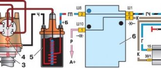
It is especially important to know how the electronic powertrain control system works. In particular, how electronic components interact with each other.
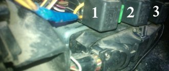
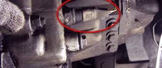
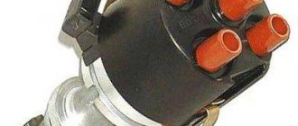
In the presented photo of the engine compartment, only some of them are noted:
- Controller that controls the fuel injection phases (in diagram 1);
- Injector with fuel frame and electric injectors (3);
- Coolant temperature sensor (15);
- Crankshaft position sensor (16);
- Throttle valve with air flow sensor (19).
Also read the article VAZ 21099 wiring diagram: differences from its predecessor
Cooling fan VAZ 2107
In the power plants of the first "sevens" the radiator fan was installed directly on the water pump shaft. Like the pump, it was driven by a belt drive from the crankshaft pulley. This design was also used on other cars at that time. It almost never failed, and it was impossible to overheat the engine with it. However, she had one drawback. The constantly cooled power unit warmed up very slowly. That is why AvtoVAZ designers changed the principle of forced airflow, replacing the mechanical fan with an electric one, and with automatic activation.
Why do you need an electric fan?
The fan is designed for forced airflow of the cooling radiator. During operation of the power plant, liquid coolant enters the radiator through the opened thermostat. Passing through its tubes equipped with thin plates (lamellas), the refrigerant cools due to the heat exchange process.
When a car moves at speed, heat transfer is facilitated by the oncoming air flow, but if the car sits for a long time or drives slowly, the coolant does not have time to cool. At such moments, it is the electric fan that saves the engine from overheating.
Device design
The radiator fan consists of three main elements:
The electric motor rotor is equipped with a plastic impeller. It is she who, rotating, creates a directed air flow. The engine of the device is installed in a metal frame, with which it is attached to the radiator housing.
How does an electric fan turn on and work?
The process of turning on the fan for carburetor and injection “sevens” is different. For the former, its activation is controlled by a mechanical temperature sensor mounted in the lower part of the right cooling radiator tank. When the engine is cold, the sensor contacts are open. When the temperature of the refrigerant rises to a certain level, its contacts close and voltage begins to be supplied to the brushes of the electric motor. The fan will continue to operate until the coolant cools down and the sensor contacts open.
What is the device
The gasoline pump is a cylindrical barrel measuring 20x15 cm, located under the hood of the car in the carburetor area. It has two tubes, one of them pumps gasoline, and the other supplies it to the carburetor. It also has a lever that is designed for manual pumping of fuel if the mechanical system is not functioning.
The design of the device includes:
- The chamber into which fuel flows from the tank.
- Fuel inlet and outlet valves.
- Diaphragm.
- The ghost lever operates the pumping mechanism.
- Return spring.
- Fist.
- Camshaft
- Sealing gasket.
The operating principle will tell you what each part does.
Operating principle
It works quite simply, just like regular water pumps. In order for the device to begin to function, a mechanical action is applied to it, carried out by the diaphragm. It moves up and down due to the effects of vacuum and pressure. During the downward stroke, a vacuum is created and fuel is sucked into the chamber. When the diaphragm moves upward, it creates pressure and the suction valve closes, and the discharge valve opens, through which fuel flows into the carburetor. The return spring performs the function of causing the movement of the diaphragm.
What are the causes of malfunctions?
The main problem that causes malfunction of the fuel pump of a VAZ-2107 car lies in the sealing gasket. It creates a sealed chamber where the phenomenon of rarefaction and pressure occurs. When this gasket wears out, the seal is broken and not only gasoline, but also air is sucked into the chamber. When the diaphragm moves back, fuel leaks out through a loose seal. Another reason for the pump not to function is clogging of the inlet valve channels. But, this problem was solved by installing a special filter element in front of the gas pump, which extends the service life of the fuel injection device much longer. Rupture of the internal membrane also poses a threat to the performance of the element. If such a problem occurs, it is very difficult to start the engine even when pumping fuel manually.
How to determine the malfunction?
For a VAZ-2107 car, it is easy to find out if the fuel pump is not working. To do this, you need to disconnect the tube from which gasoline enters the carburetor. Next, manual pumping is carried out and if liquid leakage is observed, then the cause of the malfunction is not in the fuel pump. If fuel does not come out of the tube, then the device is faulty, or rather, the problem most likely lies in the inlet valve. You can check this as follows:
- Remove the intake valve tube.
- Close the inlet port with your finger.
- Press the pump lever.
If you feel a vacuum on your finger, then the device is working properly and there is no point in disassembling it.
Fuel pump repair
The device for pumping fuel into the carburetor is subject to repair, unless, of course, the service life of the device is very long. Repair includes disassembling the device, cleaning and replacing worn parts. So, repairs are best carried out with the device removed from its seat, but there are also simple breakdowns that can be repaired without removal. Repairs are carried out in the following sequence:
- The main semicircular cover, which is secured with a bolt, is removed.
- After removing the cover, we carry out a visual inspection. The filter is removed and needs to be washed and blown out for cleaning.
- Further analysis of the device is underway. The six bolts are unscrewed using a screwdriver and the device is separated into two parts.
- The intake and exhaust valves are cleaned. You can wash it in gasoline or solvent and spray it with a stream of dense air.
- To remove the diaphragm, you need to rotate it 90 degrees and carefully remove it.
- Next, we repair the diaphragm, unscrew it and remove all the components.
- Only flexible membranes are damaged, so it is these that need to be replaced.
- When the replacement is made, it is important to assemble the diaphragm in the same sequence as originally.
- The device itself is assembled in the reverse order of removal.
- When installing the filter, it is necessary to ensure that the hole in it is located above the valve.
- By connecting the two parts, a gasket is installed, which can be additionally lubricated with sealant.
The repair is complete, all that remains is to install the fuel pump in its seat and check its functionality.
Replacing the device
If the fuel pump has outlived its usefulness, then it is better not to torture yourself and the car, but install a new part. Replacing a fuel pump on a VAZ-2107 is not difficult even for a beginner. First, disconnect the fuel hoses, then use a head to unscrew the two nuts securing the fuel pump. After this, disconnect the pump from the engine block. Before installing a new pump, clean its seat from dust and dirt. Initially, it is necessary to put a sealing gasket on the cleaned area, the thickness of which should be 0.7 mm or more.
Important! Next, a thermal insulation gasket is installed, which has a thickness of about 0.3 mm. The thickness of the two gaskets is necessary to achieve a minimum pusher exit clearance of at least 0.8 mm. Therefore, it is better to use new gaskets rather than suffer with old ones.
If the thickness is less, this may result in improper functioning of the fuel pump due to the incorrect position of the pusher. After this, the device is installed and tightened with nuts, two hoses are inserted and secured with clamps. All that remains is to check the functionality of the installed equipment.
Knowing not only how the replacement is carried out, but also the operating principle of the fuel pump of your VAZ-2107, you can easily carry out any repairs without using the help of specialists at a service station and thereby saving your money.
Unfortunately, it is possible that when you turn on your “Seven” you cannot hear the usual sound of the fuel pump, and this usually happens at the most crucial and inopportune moment. Of course, if such a problem arises, you can postpone your affairs until later and turn to a professional auto electrician for help, or you can go your own way, showing willpower and trying to fix the problem on your own.
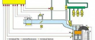
Strange as it may seem, a fairly detailed power supply diagram for the VAZ 2107 (meaning as convenient as possible for use) is a certain rarity even on the Internet, and the option given below allows, to some extent, to facilitate the search for the cause of the failure of this important unit.
If we talk about practical implementation, then the most optimal version of the algorithm for troubleshooting the electrical power circuit of the VAZ 2107 fuel pump looks like this.
First of all, you should find a panel with three executive relays located in the glove compartment area and, for ease of operation, dismantle it and pull it towards you. Next, on the middle relay (it actually supplies power to the fuel pump), with the ignition on, we measure the presence of + 12V voltage on the thick pink wire. If voltage is present, then we bridge the indicated pink wire with a thick gray wire that goes directly to the fuel pump (on the relay these are contacts “30” and “87”).
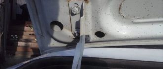
If the operation of the unit is still not audible, we proceed to check the wiring, paying special attention to the connecting connectors in the trunk, one of which is black and slightly elongated, and the second (white) is located directly on the fuel pump cover. It is characteristic that, according to the “law of meanness,” the break is most often located in the second connector, and it will not be possible to get to it without removing the pump. By the way, if the contact is actually broken in the white connector, then in order to avoid problems during further operation, you can completely eliminate it by soldering the wires directly (the load in this circuit is significant, and the contacts simply burn out).
Don’t forget, also, to check the condition of the ground wire and the reliability of its connection (black wire, screwed with a self-tapping screw in the lower right part of the trunk).
Now let’s consider the option when, when the pink and gray wires are short-circuited, the pump starts working. In such a situation, you should check for the presence of +12V on contacts “85” and “86” of relay R2. In other words, when the ignition is turned on, a stable + 12V should appear on one of the contacts (relative to the “ground” of the car), and on the other contact this voltage should remain for several seconds (when connecting the “ground” from the ECU). The normal appearance of voltage on contacts “85” and “86” indicates that the electric fuel pump is in working condition and that relay F2 is most likely faulty. If the desired voltage is not present, then the situation becomes more complicated and the search will have to be continued. At this stage, it is necessary to determine what exactly is missing from the relay. If the positive comes, then we call a thin gray wire with a black stripe and if it is not damaged all the way from the relay to the ECU, the matter is bad and you cannot do without an experienced specialist. In the event of a complete absence of voltage, both at pin “85” and at pin “86”, fuses F1, F2, F3 are sequentially checked, as well as the wiring going to the main relay.
Among other things, when dealing with the problems of powering the fuel pump, we should not forget that modern security systems quite often provide for blocking this unit as additional protection against theft, and the malfunction can be explained by malfunctions in the car alarm.
The fuel systems of classic VAZ models, such as 2106 and 2107, differ in the type of supply of the combustible mixture to the cylinders. For some, the carburetor is responsible for this, for others, the injector. However, the coordinated operation of the power unit for both depends not on the design of the system, but on the serviceability of its elements, and primarily the fuel pump. Every car enthusiast should, if necessary, be able to repair and replace this element with his own hands.
Fan motor
The electric motor is the main component of the device. The VAZ 2107 used two types of engines: ME-271 and ME-272. In terms of characteristics, they are almost identical, but as for the design, it is somewhat different. The ME-271 engine has a stamped housing, i.e., non-separable. It does not require periodic maintenance, but in case of malfunction, it can only be replaced.
Design and characteristics of the fan motor
Structurally, the motor consists of:
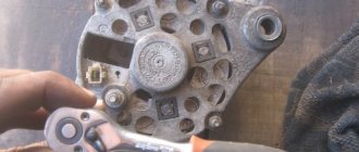
The ME-272 electric motor also does not require maintenance, but unlike the previous model, if necessary, it can be partially disassembled and attempted to be restored. Disassembly is carried out by unscrewing the tightening bolts and removing the back cover.
In practice, repairing an electric fan is impractical. Firstly, you can only buy used spare parts for it, and secondly, a new device complete with impeller costs no more than 1,500 rubles.
Table: main technical characteristics of the ME-272 electric motor
| Characteristics | Indicators |
| Rated voltage, V | 12 |
| Rated rotation speed, rpm | 2500 |
| Maximum current, A | 14 |
Additional designations
The fuses of the VAZ 2107 car are located as follows:
- taillights and reversing lights;
- electric motor of the heater fan, headlight washer and glass wiper pumps;
- indicator for turning on the rear window heater VAZ 2107;
- direction indicators and hazard warning relays;
- fog lights;
- tachometer, voltmeter;
- control lamps for oil pressure, fluid, fuel level and reserve indicators on the instrument panel, instrument panel lighting;
- cigarette lighter and clock;
- VAZ sound signal;
- interior lighting (up to 2000 there was one lamp on the ceiling, for those manufactured after 2000 there were two lamps on the rear door pillars);
- high beam headlights;
- high beam warning lamp;
- engine compartment lighting and license plate lighting;
- glove compartment lighting;
- right headlight;
- left headlight.
Cooling fan malfunctions and their symptoms
Taking into account the fact that the fan is an electromechanical unit, the operation of which is ensured by a separate circuit, its malfunctions can manifest themselves in different ways:
The fan doesn't turn on at all
The main danger posed by a broken cooling fan is overheating of the power plant. It is important to control the position of the arrow of the temperature indicator sensor and feel the moment the device turns on. If the electric motor does not turn on when the arrow reaches the red sector, most likely there is a malfunction of either the device itself or the elements of its circuit. Such breakdowns include:
Diagnostics and repair
It is recommended to check the fan and elements of its electrical circuit in the following order:
Checking the functionality of the fuse
The fuse is usually checked first, as this process is the simplest and does not take much time. To carry it out, you only need an autotester or a test lamp. The essence of the diagnosis is to determine whether it passes electric current.
The fan circuit fuse is installed in the vehicle's mounting block, which is located in the engine compartment. In the diagram it is designated as F-7 with a rating of 16 A. To check and replace it, you must perform the following work:
Relay diagnostics
As we have already said, in the injection “sevens” a relay is provided to unload the electrical circuit of the radiator fan. It is installed in an additional mounting block located under the glove box in the car interior, and is designated R-3.
Checking the relay yourself is quite problematic. It is much easier to take a new device and install it in place of the one being diagnosed. If the electric fan turns on when the refrigerant is heated to the desired temperature, then that was the problem.
Causes
There are several reasons why a VAZ fuel pump may not work:
- no power to the fuel pump;
- motor is faulty;
- pump is faulty.
Let me clarify some points. If the electric motor malfunctions, power is supplied to it, but if the brushes are broken, the rotor or windings are faulty, the motor will not spin and you will not hear a characteristic hum.
If the fuel pump malfunctions, a hum will be heard, but there will not be enough fuel or, in my case, the pump is simply jammed.
Forced fan activation
Some owners of “classics”, including the VAZ 2107, install a forced fan button in their cars. It allows you to start the electric motor of the device regardless of the coolant temperature. Taking into account the fact that the design of the 7’s cooling system is far from ideal, this option could one day be of great help. It will also be useful for those drivers who often travel along country roads or are forced to stand in traffic jams.
Forced activation of the fan is appropriate only on carburetor cars. In cars with injection engines, it is better to rely on the electronic control unit and not make any changes to its operation.
Video: forcing the fan to turn on
The easiest way to make the fan turn on at the driver's request is to bring two wires from the contacts of the temperature sensor into the passenger compartment and connect them to a regular two-position button. To implement this idea, you only need wires, a button and electrical tape or heat shrink insulation.
If you want to “unload” the button from unnecessary loads, you can install a relay in the circuit according to the diagram below.
In principle, there is nothing complicated either in the design of the fan itself or in its connection circuit. So, in case of any breakdown, you can safely proceed to self-repair.
Source
Injector maintenance
Since the injection power system is quite complex, during the operation of the car there is a need to eliminate failures and failures. You can service the car yourself if you have a detailed diagram. In particular, engine management systems:
To troubleshoot you need:
- availability of electronic testers (their price is low - you should definitely buy them);
- adapters through which the tester is connected to the diagnostic connector.
By comparing the measurement results with operating parameters, you can easily identify an electrical circuit operating with deviations. And only then, when analyzing it, detect a non-working device: sensor or wiring.