High voltage wires
High voltage wires (HVW) transmit impulses from the coil to the spark plugs. Unlike other wires, they must not only withstand high voltage, but also protect other parts of the car from it. Each wire consists of a conductor with an iron tip, rubber caps on both sides and insulation. The serviceability and reliability of the insulation is of great importance, because it:
- prevents water from entering the conductive element;
- reduces current leakage to a minimum.
Adjusting the gap between contacts
Before making adjustments, you need to remove the distributor cover. For VAZ 2107, the closed contact angle should be 55±3˚. This angle can be measured using a tester or probe using the gap between the contacts in the open state. To make it easier to adjust the gap, it is recommended to remove the distributor from the car, but after that you will have to set the ignition again. But this can be done without dismantling.
To check the size of the gap, the crankshaft is rotated to the position at which this gap will be greatest. Measured with a feeler gauge, the gap should be 0.35–0.45 mm. If its actual value does not fall within this interval, adjustment is required in the following manner.
- Use a screwdriver to loosen the contact group fasteners and the adjustment screw.
Preparatory stage
To set the ignition on a VAZ 2107 car, no special conditions are required; the operation can be done both in the garage and on the street, including in winter. For work, prepare the following set of tools:
- flat screwdriver;
- metal probe 0.35 mm thick;
- open-end wrench size 13 mm;
- a car light bulb designed for a voltage of 12 V with wires soldered to it;
- a wrench with a long handle designed to turn the crankshaft;
- key for unscrewing spark plugs.
Ignition tuning tool
Note. Instead of a special key to rotate the crankshaft, you can use a regular open-end wrench measuring 36 mm. If you don’t have such a key, then you will have to set the marks in the old proven way: by engaging 4th gear and raising the rear wheel, turn it manually, thereby turning the crankshaft.
Ideally, it is better to have in your arsenal a device for setting the ignition on a running engine - a strobe light. It is equipped with a lamp that flashes simultaneously with the moment of spark formation in the cylinder, which allows you to see the position of the notch on the crankshaft pulley at idle speed and clearly adjust the advance angle.
Important point. The ignition is set in order to ensure that the spark appears in a timely manner and the engine starts, after which additional adjustments will be required. But the latter will not bring you the desired result when there is no compression in the cylinders or problems with the carburetor make themselves felt. If these faults are not eliminated, the engine operation will remain unstable, no matter how you configure the spark generation system.
Diagnostics, installation and ignition adjustment of injection and carburetor models VAZ 2107
At some point, the owner of a VAZ 2107 will be faced with the need to adjust the ignition system. This may be due to a violation of the ignition of the mixture in the cylinders, the replacement of a contact distributor with a non-contact one, etc. It is quite easy to adjust the ignition system of traditional VAZ models.
Methods for setting the ignition angle
You can adjust the ignition timing using various methods.
- Aurally.
- Using a light bulb.
- By strobe light.
- By spark.
The choice of method depends first on the availability of the necessary devices and means at hand.
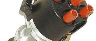
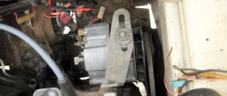
Contact distributor VAZ 2107
The distributor in the ignition system performs the following functions:
- begins the process of spark formation;
- transmits the highest voltage from the coil to the spark plugs;
- keeps under control and regulates the moment of spark formation depending on the fuel and driving mode.
The distributor is rotated by the crankshaft through a number of additional parts. It wears out with use and requires repeated inspection and maintenance. In all this, increased attention should be paid to his contacts.
Tuning on carburetor modifications of the VAZ 2107
All old textbooks on servicing traditional Zhiguli models describe a method for setting the moment of spark formation using a light bulb, although experienced motorists can quietly do without it. You will understand why this happens as you read this material, but for newcomers it is useful to familiarize yourself with the old, proven technique.
In order to correctly set the ignition of the “seven”, it is necessary to ensure the simultaneous fulfillment of the following criteria:
- the notch on the crankshaft pulley is opposite the long mark on the timing cover;
- with all this, the round mark marked on the camshaft chain drive gear coincides with the boss on its body;
- the piston of the 4th cylinder has completed the compression stroke and is at top dead center; the contacts inside the distributor are open;
- The movable contact of the slider faces the fixed contact on the distributor cover, where the wire from the spark plug of the 4th cylinder is connected.
Note. On contactless systems, at this moment the Hall sensor sends a signal to the switch to break the low-voltage electrical circuit, which leads to the appearance of a high-voltage pulse on the wire leading to the spark plug of the 4th cylinder.
The light bulb is used to control the ignition timing, why it must be connected with one wire to the “K” contact of the high-voltage coil, and the second to the vehicle ground. You need to know that at the same moment the piston of the first cylinder is also in the TDC position, only there is not compression of the air-fuel mixture, but the release of exhaust gases after its combustion. This is why uninformed car owners often confuse cylinder 1 with cylinder 4 when installing the ignition.
READ How many amperes does the VAZ 2107 generator produce?
When the above actions occur immediately, a spark discharge occurs on the electrodes of the spark plug of the 4th cylinder, as evidenced by the flash of the connected light bulb. To achieve these criteria and set the ignition correctly, follow the instructions:
- Turn the crankshaft with a 36 mm wrench, aligning the notch on the pulley with the long notch on the timing cover.
- If at this moment the engine valve cover is removed, then it is better to navigate by the mark on the camshaft gear, placing it opposite the housing boss.
- Take the ignition distributor, remove the cover and turn its shaft to place the slider opposite the wire leading to the cylinder (there are cylinder numbers marked on the cover). Insert the distributor into the hole in the motor, holding the slider and housing in this position, then secure it with a 13 mm wrench nut.
- Connect the light bulb wires and turn on the ignition by turning the key. Loosen the nut securing the distributor and slowly turn it by the housing until the lamp flashes, indicating the moment of sparking. Reattach the distributor.
- Turn off the ignition and make sure that at this moment the contacts inside the distributor are open. Take a 0.35 mm feeler gauge and check the gap between them, adjust it as necessary by loosening the fastening screws with a screwdriver.
Note. The summary suggests that before the work, the distributor was removed from the engine without aligning the marks.
The ignition is considered to be set correctly if, after installing the distributor cap and connecting the wires, you can start the engine, and then you need to adjust the advance angle. The non-contact system is installed in the same way, except for checking the gap in the contact group due to its absence.
Fundamental point. Almost always, the ignition is set without removing the valve cover, which is why the position of the mark on the gear is not visible. You have done everything according to the instructions, but the engine does not start. This means that a spark is supplied to the 4th cylinder during the exhaust stroke, and compression at this moment occurs in the first cylinder. The problem is easily resolved:
- remove the distributor cover;
- unscrew the nut securing it;
- remove the distributor from the socket, turn the slider exactly 180° and insert the element back;
- Press the distributor skirt with the nut and install the cover.
Advice. If the engine does not start after these steps, but begins to show signs of life, then the problem lies not in the ignition setting, but in a malfunction of one of the parts of the system.
Checking and adjusting the lead angle
To check whether the ignition is set correctly, just align the marks on the crankshaft pulley and the timing cover. In this case, the slider should be directed to the 4th cylinder, and the contacts should be open. If the slider “looks” towards the first cylinder and the car does not start, then turn it 180° as described above.
To create optimal fuel combustion conditions in the chamber, the flash should occur a little earlier than the piston reaches TDC. There are 3 ways to achieve this:
- when installing the ignition, align the notch on the pulley not with the first long mark, but with the second, indicating an advance angle of 5°;
- determine the amount of advance “by ear” by loosening the nut securing the distributor and turning it by the housing at idle engine speed;
- connect a strobe light to the system, start the engine and by turning the distributor, adjust the position of the notch by pointing the flashing lamp of the device at it.
The advance angle is adjusted by turning the distributor housing
Reference. The second method is most often used by experienced drivers, since it gives a positive result without any instruments. The ignition distributor is turned until the position of the most stable engine operation is found. That is why the use of a light bulb does not play a big role, because the real advance angle at which the engine operates in optimal mode lies in the range of 5-10° and is determined individually in each car experimentally.
Once the settings are complete, press the gas pedal sharply several times. If you can hear the piston pins knocking (a ringing sound is clearly audible from the engine), then the advance angle is too large. Loosen the distributor and turn it 1-2° clockwise, then check again by pressing the accelerator.
Advice. Finger tapping is often heard when you fill with low octane fuel. Then it is necessary to reduce the advance angle so that detonation (which causes knocking) does not destroy the piston group. When using high-quality fuel, the angle should be increased in order to improve the dynamic characteristics of the VAZ 2107.
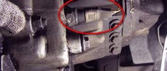
How to change high-voltage wires on a VAZ 2107 injector
In order to correctly set the ignition of the “seven”, it is necessary to ensure the simultaneous fulfillment of the following criteria:
- the notch on the crankshaft pulley is opposite the long mark on the timing cover;
- with all this, the round mark marked on the camshaft chain drive gear coincides with the boss on its body;
- the piston of the 4th cylinder has completed the compression stroke and is at top dead center;
- the contacts inside the distributor are open;
- The movable contact of the slider faces the fixed contact on the distributor cover, where the wire from the spark plug of the 4th cylinder is connected.
Note. On contactless systems, at this moment the Hall sensor sends a signal to the switch to break the low-voltage electrical circuit, which leads to the appearance of a high-voltage pulse on the wire leading to the spark plug of the 4th cylinder.
The diagram shows what happens in the cylinders when the marks are aligned
The light bulb is used to control the ignition timing, why it must be connected with one wire to the “K” contact of the high-voltage coil, and the second to the vehicle ground. You need to know that at the same moment the piston of the first cylinder is also in the TDC position, only there is not compression of the air-fuel mixture, but the release of exhaust gases after its combustion. This is why uninformed car owners often confuse cylinder 1 with cylinder 4 when installing the ignition.
Layout of marks on the timing cover
When the above actions occur immediately, a spark discharge occurs on the electrodes of the spark plug of the 4th cylinder, as evidenced by the flash of the connected light bulb. To achieve these criteria and set the ignition correctly, follow the instructions:
- Turn the crankshaft with a 36 mm wrench, aligning the notch on the pulley with the long notch on the timing cover.
- If at this moment the engine valve cover is removed, then it is better to navigate by the mark on the camshaft gear, placing it opposite the housing boss.
- Take the ignition distributor, remove the cover and turn its shaft to place the slider opposite the wire leading to the cylinder (there are cylinder numbers marked on the cover). Insert the distributor into the hole in the motor, holding the slider and housing in this position, then secure it with a 13 mm wrench nut.
- Connect the light bulb wires and turn on the ignition by turning the key. Loosen the nut securing the distributor and slowly turn it by the housing until the lamp flashes, indicating the moment of sparking. Reattach the distributor.
- Turn off the ignition and make sure that at this moment the contacts inside the distributor are open. Take a 0.35 mm feeler gauge and check the gap between them, adjust it as necessary by loosening the fastening screws with a screwdriver.
READ Where is the central locking fuse for VAZ 2110
The marks need to be combined by turning the crankshaft with a key
Note. The summary suggests that before the work, the distributor was removed from the engine without aligning the marks.
The ignition is considered to be set correctly if, after installing the distributor cap and connecting the wires, you can start the engine, and then you need to adjust the advance angle. The non-contact system is installed in the same way, except for checking the gap in the contact group due to its absence.
The mark on the camshaft gear is aligned with the boss on the body
Fundamental point. Almost always, the ignition is set without removing the valve cover, which is why the position of the mark on the gear is not visible. You have done everything according to the instructions, but the engine does not start. This means that a spark is supplied to the 4th cylinder during the exhaust stroke, and compression at this moment occurs in the first cylinder. The problem is easily resolved:
- remove the distributor cover;
- unscrew the nut securing it;
- remove the distributor from the socket, turn the slider exactly 180° and insert the element back;
- Press the distributor skirt with the nut and install the cover.
Advice. If the engine does not start after these steps, but begins to show signs of life, then the problem lies not in the ignition setting, but in a malfunction of one of the parts of the system.
Types of systems
For decades, while the VAZ 2107 model was produced (from 1982 to 2012), it was equipped with three types of ignition systems:
- mechanical with contacts - breakers;
- contactless;
- controlled by an electronic unit (ECU).
Contact ignition circuit installed in the first VAZ 2107 models
Note. The first 2 varieties were installed on the “seven” with a carburetor, the latter was introduced together with an injector.
In the mechanical version, the contacts opened by the cam of the distributor shaft break the low voltage circuit, initiating the formation of a powerful pulse in the secondary winding of the coil. This discharge is directed to the electrodes of the spark plug, which ignites the fuel in the cylinder where the piston has risen to top dead center (TDC) and the compression stroke is completed.
Scheme of non-contact ignition of the seven with a carburetor
The contactless circuit operates on the same principle, only the signal to break the circuit is supplied by the Hall sensor, and it is implemented by the switch. Therefore, setting the ignition on carburetor “sevens” is done almost identically. Another thing is cars with an injector, where a new system has been introduced that does not have not only contacts, but also a distributor and any moving parts. Here, the moment of spark formation is determined by the ECU controller, which is guided by the signals of various sensors.
Setting the ignition
The next fundamental problem among VAZ 2107 owners who have an injector will be how to accurately set the ignition.
As is clear, in such models all engine control is carried out electronically, therefore for this work you will need a computer, installation of a special program on it for the engine of an injection car, a tester, as well as keys and screwdrivers.
First turn on the ignition and ground to make sure the electric pump is working. If it does not work, then check the relay that controls it.
Is the fault light flashing? Connect your own individual laptop with a special program to the car's on-board vehicle to try to establish the cause using the available data.
If the engine is working properly, you should start it and check the throttle device: throttle position sensor, throttle opening level (less than 1%) and passing wires. Using a tester, determine the voltage of the sensor (it should not exceed 0.55 volts) and the on-board network (its voltage should exceed 12 volts).
Perform the same actions again, but with the gas pedal pressed all the way. Now all readings should change, because the sensor voltage is normally approximately 4-4.5 volts, and the throttle opening fluctuates around 90%. Adjust the throttle to full opening and turn off the additional air flow, and then start the engine and fix the throttle opening halfway. Now you should adjust the throttle to completely close the hole.
You see, there is nothing difficult either in installing the coil yourself, or in setting the ignition on a given car model. Now you can decide for yourself whether to contact specialists or not. Remember that by doing small checks and small repairs on the VAZ 2107 at the right time, you will always be convinced of the reliability of your own “iron horse”.
The VAZ 2107 ignition module ( injector ) is a unit whose malfunctions are quite difficult to diagnose. Problems with the module's operation are noticed only after serious engine malfunctions occur. If the engine does not start, you should try adjusting the ignition. If the engine is running unevenly, a serious check of the functionality of the VAZ 2107 .
Ignition is an electronic system for converting the low voltage of the vehicle's on-board network into high voltage and supplying the latter to the electrodes of the spark plugs.
Checking the ignition system elements
Misfires in engine operation, especially in wet weather, are a consequence of breakdown of the insulation of high-voltage wires. There should be no cracks or damage in the wire insulation. You can check the insulation for breakdown using a wire connected to ground. If you run it along the insulation while the engine is running, a spark will be observed in places with damaged insulation. Another clear sign of poor insulation is noticeable electric shocks when touching high-voltage wires while the motor is running.
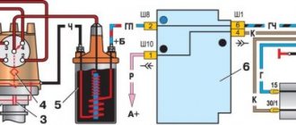
Ignition coil
A broken high-voltage wire can be easily determined with an ohmmeter. The resistance should be between 3-10 kOhm. The spread of indicators between the wires should be no more than 1-2 kOhm.
The spark plugs must not show any visible damage. It is necessary to check that the gap between the contacts is 0.8 mm.
You can check the operation of the candle visually. To do this, you need to unscrew the spark plug, apply it to ground and connect the high-voltage wire. If you start turning the starter, you should see a clearly visible spark between the electrodes on the spark plug. If it is missing or it breaks in a different place, the spark plug needs to be replaced.
About their device
Before finding out the importance of the elements of the ignition system in question, it is necessary to understand their structure. Structurally, the high-voltage wire consists of the following parts:
- A conductor through which current flows.
- Insulation - rubber or silicone is used as an insulating material.
- Protective caps on both ends.
- Metal contacts.
Each element performs corresponding tasks, and at the slightest violation of integrity, it will be necessary to replace it. Armored wires cannot be repaired, since they play one of the main roles in the car’s ignition system, and also belong to the category of consumables.
This is interesting! Few people know that on a car it is necessary to change not only the spark plugs, but also the armored wires, which wear out over time and begin to malfunction.
To distributor or MZ
It is a mistaken belief that armored wires on a car are ordinary wires that are designed to transmit current from a source to a receiver. 2107 cars were produced in two variations of the fuel supply system - carburetor and injector . Although many parts and mechanisms on the carburetor and injector are the same, this does not apply to the GDP. The carburetor VVP differs from the injection one on the VAZ 2107 in the following parameters:
- The length, on which the amount of resistance also depends. The wires on the injection unit are shorter than on the carburetor.
- Fasteners that connect to the distributor on the carburetor and the ignition module on the injector.
- The amount of GDP. There are four of them on the injector, and five on the carburetor.
- Type of caps.
READ How to open the hood of a VAZ 2107 from the outside
Knowing the design differences, you must also understand that high voltage flows through the wire. The current comes from the distributor or MG through the wires to the spark plugs. The slightest malfunctions lead to the fact that current is not supplied to the spark plug, and a spark does not occur. If a spark does not occur, the cylinder does not work, which negatively affects the operation of the engine.
We spread the ignition wires
Replacing Armored Pipelines - logbook Lada 2107 Three funny letters - VAZ 2005 on DRIVE2
Hello everyone who reads our BZ!
A couple of months ago, a bearing on our water pump fell apart, so the entire engine compartment was filled with antifreeze! not a pleasant sight...
Yesterday leaving on the street. Antonova felt that the engine was not working! This lasted for about a minute, then everything returned to normal.
Today I went to the parking lot to figure out what the problem was! I removed the armored wires... and was horrified! The antifreeze and the terminal of the 3rd wire on the side of the ignition module reacted and oxidized! and it's terrible! That's the problem!
I decided to clean it! I took a cloth and a screwdriver, and as soon as I touched the metal contact it fell off! that's not a problem...
I had to go to the store for wires! bought HOLA for 2108 - 2115! have arrived!
The old wires went into the trash along with the packaging from the new ones! :)
I took alcohol, a rag and washed all the contacts in the ignition module!
In one thing I cleaned the terminals on the mass air flow sensor and DPKV!
To your liking:):) creative sticker!:)
Issue price: 315 ₽
General tips for connecting high-voltage wires.
Checking high-voltage wires. To check the wires, you will need a multimeter tester. Check the resistance of the wires - it should be no more than 20 KOhms (in practice, the longest wire of cylinder 1 has a resistance of up to 10 KOhms). If the wire resistance is more than 20 Kom, it must be replaced. Carefully inspect the wires for chafing on parts of the motor or other wires. In case of significant abrasion, the wire . In case of minor abrasion, it is possible to lay the wire so that it does not rub and fix it in this position.
Laying wires. Do not try to connect the wires in a bundle. Disassemble the wiring harnesses, release the wires from the plastic holders. Connect the high-voltage leads to the corresponding cylinder spark plugs. Lay the wires so that they do not rub against each other, engine parts, or hoses. Avoid sharp bends and tension on the wires. After connecting all the wires, secure them into the bundle with special comb holders included in the delivery kit.
The procedure for connecting I/O wires to a VAZ carburetor (2108, 2109, 21099)
The central wire from the distributor cover always goes to the ignition coil (bobbin).
VAZ 2107 replacement of spark plugs and armored wires
The outlet of the distributor cover, which faces towards the front of the car, is connected to the first cylinder.
The outlet of the distributor cap, looking down, is connected to the third cylinder.
The outlet of the distributor cap, looking rearward, is connected to the fourth cylinder.
The outlet of the distributor cap, looking up, is connected to the second cylinder.
The procedure for connecting high-voltage wires to a VAZ Classic, Niva with a carburetor and distributor.
Central wire from the ignition coil (bobbin)
1 cylinder - above the vacuum corrector. Next, clockwise, the order is 1-3-4-2.
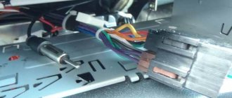
Injection VAZ produced before 2004 with an old-style ignition module (4-pin low-voltage connector)
Actually, on the module body it is already indicated which cylinder the pins correspond to - but we duplicated them in red in case the module gets completely dirty, and you might not be able to see it in the photo.
Injection VAZ produced after 2004 with a new ignition coil (3-pin low-voltage connector)
As with the old-style ignition modules, the new coils are also marked with pins corresponding to the cylinders. But the connection order is different from the order on the old-style ignition module. Be careful.
Mounting block
All wiring harnesses of the “seven” converge to the mounting block, which is installed in the right rear part of the engine compartment. It contains fuses and relays for the machine's on-board network. The mounting blocks of carburetor and injection VAZ 2107 are almost the same structurally, however, in “sevens” with distributed injection there is an additional relay and fuse block, which is located in the cabin.
In addition, there are machines equipped with old-style blocks designed for the use of cylindrical fuses.
Let's consider what protection elements ensure the safe operation of the VAZ 2107 on-board network.
Replaced BB wires from Cargen to Slon
The other day it got warmer outside and it seemed that the car started to pull weakly, the ECU did not give any errors, I decided to look at the explosive wires.
Let me remind you that the summer before last I changed the module, and at the same time installed new Cargen wires - the same ones were installed when buying the car, and they were inexpensive, something around 400 rubles.
Just a few months later the tip on the 3rd spark plug melted and bent because the wire was too short. But, since this did not affect the spark in any way, I scored it and left it like that. Now a small oxide has already formed there.
Read more: Rack Renault Megan 2
White oxides also formed on the contacts to the module of a pair of wires, and drops of moisture were present in one of them; perhaps moisture had entered during the engine washing.
I also looked under the hood when it got dark - there was a glow coming from all the candlesticks (I couldn’t take a photo).
Therefore, I decided to replace the wires completely with new ones. I decided to try it under the Elephant brand, many people recommend them, and they go to the AvtoVAZ assembly line.
Before installation, I checked their resistance with a multimeter. For spark plug wires on a VAZ it should be 3.5-10 kOhm.
As we can see, the resistance of these wires is within 4-6 kOhm. The 4th wire has a larger value, apparently due to its length.
The wires are a little tighter compared to before, the rubber insulator moves very tightly, it is almost impossible to push it along the wire, with Kargen it was much easier to stretch it onto the spark plug. For the third spark plug, the wire length is again not enough, for some reason it is the same length as the first 2 from both companies. I hope the candlestick doesn’t bend again.
Externally, the wires do not differ much from each other, although the Elephant has softer silicone and the contacts seem to be brass.
I decided to similarly check the resistance of the old wires.
As you can see, the spread is significant, although, apparently, initially Kargen’s resistance was in the region of 2-3 kOhm.
After replacing the wires, the behavior of the car did not change, but sparking from the candlesticks still occurs. Maybe this is normal? Or is the reason something else?
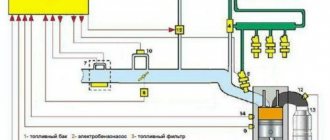
One of the weakest points of any car, including the VAZ 2107, is the ignition system. This system consists of many elements that together ensure the correct and continuous operation of the seven engine. One of the constituent elements of the ignition system are armored wires or high-voltage wires of the GDP, which are responsible for supplying voltage to the spark plugs.
Features of the design of the on-board network of the VAZ 2107
The “sevens”, like most modern cars, use a single-wire circuit for supplying electricity to electrical equipment. We all know that power to devices is supplied through only one conductor - the positive one. The other terminal of the consumer is always connected to the ground of the machine to which the negative terminal of the battery is connected. This solution allows not only to simplify the design of the on-board network, but also to slow down electrochemical corrosion processes.
Sources:
https://www.vazzz.ru/kak-pomenyat-vysokovoltnye-provoda-na-vaz-2107-inzhektor/ https://21074.ru/dvigatel/ustanovka-zazhiganija-na-vaz-2107-video-instrukcija/ https://a116.ru/site/stati/vysokovoltnye-provoda-i-svechi/poryadok-podklyucheniya-vysokovoltnyh/ https://bumper.guru/klassicheskie-modeli-vaz/elektrooborudovanie/elektroshema-vaz-2107.html