Purpose
Obviously, the car's reverse mode is designed to accelerate the car in the opposite direction without resorting to a 180-degree turn.
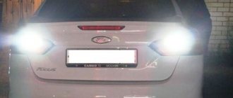
This allows you to park more comfortably, maneuver faster and, finally, save time for yourself and other drivers. A reverse signal is needed to warn surrounding drivers of an upcoming maneuver, similar to the way turn signals or brake lights do, embedded in the taillights.
The reverse alarm is also intended for maneuvering in the dark and in fog. A lamp that has a fairly powerful light beam allows the driver to better see what is happening behind the car and avoid annoying accidents and incidents when maneuvering
In any case, it is worth paying attention to the condition and operation of the lights. This will eliminate most problems and protect the car from accidental damage.
The principle of operation of the brake light
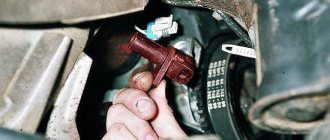
Reverse sensor for a VAZ 2114 car.
The brake lights are located at the rear of the car. Red lanterns. They light up automatically if the driver brakes. When the driver takes his foot off the brake pedal, they are also automatically turned off. The presence of stops is mandatory for vehicles.
The lights should be located symmetrically and burn brighter than the side lights. Brake lights are installed on the sides, on the rear window, in the center above the line of the side stops.
Primary and secondary brake lights can be a single bulb, a neon tube, or a set of LED bulbs. The car enthusiast is additionally equipped with a brake light repeater. The rear brake light can also serve as a fog light. You can install a formula 1 brake light (the author of the video is Mikhail Ermolaev).
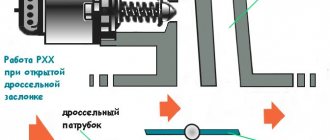
The simplest brake light includes a breaker (switch) and a flashlight. The brake light switch is often called the frog switch. The plastic body of the breaker contains two terminals, a rod and a spring. This device is installed on the brake pedal.
When the driver presses the pedal, the rod enters the breaker body, the contact closes and the light comes on. As soon as the driver removes his foot from the brake pedal, the spring pushes out the rod, the contacts open and the light goes out.
LED brake lights consist of a chip and a sensor, which in this case is a frog, it sends a signal when the driver presses the brake. As with the single lamp, the frog is mounted under the brake pedal.
Foot control device diagram
Any pedal has free play. Therefore, although the driver presses the pedal, the car does not brake immediately. The brake light comes on as soon as the brake pedal is pressed. Drivers of vehicles behind will become aware of braking before the vehicle begins to brake. This way they have time to prepare for braking.
Design and principle of operation of the sensor
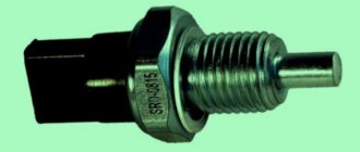
The DZH of the VAZ 2115 car has a very simple design. This product consists of the following parts:
- Sealed housing.
- Non-latching switch.
- Pusher.
- Output terminals.
The sealed housing reliably protects the moving contacts of the switch from the penetration of oil, water and dirt. Part of the outer metal shell is made in the shape of a hexagon, thanks to which the element can be tightened using a wrench.
The switch is driven by a pusher, and a special spring is used to return the contacts to their original position. The electrical system plug is connected to the output contact. The electrical system of the VAZ 2115 uses a device of this type with two contacts.
DIY replacement instructions
Replacing the idle speed solenoid valve VAZ 2107
Now let's take a closer look at how the replacement is performed.
Let's consider the procedure using the example of a VAZ 2110 car:
- First, the car is driven into a pit. The area around the installed device must be cleared of dirt, since after removing the device, all dust and debris will get into the transmission. And this, in turn, can lead to its failure.
- Next, the crankcase protection is removed; to do this, you will need to unscrew several bolts.
- Now you will need a small container to collect the oil from the gearbox. When dismantling the DZH, part of the lubricating fluid will come out of the seat, which will subsequently need to be refilled.
- Disconnect the power connector from the controller and unscrew it from the installation location.
- Then clean the socket so that the new device can be installed in the seat without any problems. Install the new controller, do not forget the O-ring.
- Next, you will need to fill the transmission with the required amount of lubricating fluid, that is, what you drained needs to be poured back. But if the lubricant that you collected when removing the DZH contains traces of wear products, for example, metal shavings or sediment, then you need to think about replacing the fluid. Or, at a minimum, you need to fill the box not with collected oil, but with new one.
- Then all you have to do is reassemble all the elements in the reverse order and check the functionality of the installed DZH.
Description of DZH
Replacing the speed sensor Lada 2107 (VAZ 2107)
Purpose
Let's start with the purpose. DZH is a device designed to activate white lamps, indicating that the car is in reverse gear. The device is used to turn on the reversing lights, which allows other road users to know the driver's intentions and the maneuvers he is about to perform.
When it's dark outside, white headlights will also help warn drivers behind you that your car is in their path. This, in turn, helps prevent possible incidents and emergency situations on the road. Where this device is located - the location may vary slightly, but as a rule, the controller is located on the gearbox.
Design and principle of operation
The DZH itself consists of a housing, contacts for connection, a rod, a moving ball, and a return spring.
As for the operating principle, it is as follows:
- The driver shifts the transmission lever to the reverse gear position.
- In this case, the gear shift fork is pressed against the controller.
- Next, the device shorts the cable to ground.
- After this, the light source installed in the rear lights is activated, which warns other drivers that the car has started to reverse.
Symptoms of a problem
What signs of malfunction may indicate a breakdown of the DZH:
- One of the problems that happens most often is oxidation of contacts on the terminals or wiring. This problem is relevant for many car owners. To solve this problem, it is necessary to thoroughly clean the contacts and then install them in place. When performing this work, the battery should be disconnected. If the contacts are inoperative due to the fact that they are burned out, then they will have to be changed in any case. But before making a replacement, it is necessary to find out why the burnout occurred; most likely, the essence of the problem lies in voltage surges in the on-board network.
- The device became loose in its seat. During vehicle operation, the controller may slightly move out of its installation location; this problem is usually caused by high vibrations. In this case, you will simply need to more securely fix the device at the installation site.
- Another reason for inoperability is the lack of contact with the on-board network in the gearbox. In this case, it is necessary to diagnose the condition of the contacts, as well as electrical circuits. If necessary, failed components must either be cleaned or replaced.
- The next problem is that there is no contact between the connection connector and the safety mounting block. In this case, you also need to diagnose the condition of the contacts, as well as clean and change the wires, if necessary.
- Failure of the safety device. In this case, the problem can only be solved by replacing the fuse. If this part often fails, then the reason may lie in the same voltage surges. It is necessary to check the electrical circuit more carefully.
- The reverse light may not turn on because the light source itself, that is, the lamp, has burned out. In this case, you will have to dismantle the optics cover in the trunk and replace the failed device.
- And finally, the last reason for inoperability is the breakdown of the DZH. In this case, you will not be able to repair it, since such devices, as a rule, cannot be repaired. The controller will need to be changed (the author of the video is the Do-It-Yourself Auto Repair channel).
Replacing the sensor
Turning on the reversing lights of a VAZ 2110. Reverse does not light up
How to choose a new sensor instead of a broken one? In fact, nothing complicated: just don’t buy products from counterfeit manufacturers. Given the availability of packaging technologies, it will not be possible to determine authenticity on your own. Therefore, the only “recipe” is to visit AvtoVAZ brand stores.
When replacing the sensor, you must follow certain steps:
- Before installing a new sensor, you must wait until the gearbox oil drains and clean the threaded hole.
- Be sure to check the sealing washer; without it, oil will leak out of the box.
- After tightening the sensor in the gearbox housing, add oil to the standard level.
- The final touch - before connecting the connector, lubricate the contacts with a special anti-corrosion compound.
Thus, the installation of the sensor will be successful.
Repair is not possible, unit replacement
How to change the reverse sensor on a VAZ 2107? If you haven't touched it with a key for a long time, the task is not easy. The device itself is located in the upper part of the gearbox housing, closer to the bottom: oil does not leak from the manual transmission.
After disconnecting the connector block, just pull off the fastening nut with a 22mm wrench and carefully unscrew the sensor. The difficulty may be that under difficult operating conditions (dirt, temperature changes, road reagents), the threaded connection may stick to the body. In this case, you will have to use extreme dismantling methods: penetrating lubricant, local heating.
Important: Before installing a new sensor, the threaded connection on the gearbox must be thoroughly cleaned.
After installing the device in the hole, lubricate the contacts with a special anti-corrosion compound and only then put on the connector.
Replacement of reverse sensor VAZ 2107
If the white lights on the rear of the “Seven” stop glowing when moving in reverse, then the malfunction requires immediate correction. Not only do non-working reverse lights do not meet the technical requirements for the car and traffic rules, but this breakdown misleads other road users and can provoke an accident; as a rule, the reverse sensor on the VAZ 2107 can be to blame.
Usually, in order to eliminate such a malfunction, it is necessary to replace the VAZ 2107 reverse sensor. It is not necessary to spend time and money on a visit to service station specialists - you can diagnose and replace the sensor yourself. But first you need to make sure that it was he who caused the malfunction.
Why don't the reverse lights come on?
There are several reasons why the lamps in the reversing lights may not light:
- The fuse protecting the power supply circuit for the reverse lamps has blown. The breakdown is visible visually; you just need to pull the fuse out of the block.
- The lamps have burned out. To check the functionality of the lamps, they should be removed one by one from the lantern and make sure that there is no break in the spiral using an ohmmeter (multimeter) or a continuity tester.
- Wiring is damaged. You can also check it using a multimeter and a continuity test, but finding a break will be much more difficult.
- Poor contact of wires with the terminals of the reverse sensor. The check should begin with a visual inspection and cleaning of dirt and oxides. Then you can use a multimeter to measure the resistance of the circuit.
- There is a short circuit in the power wires. You can check the absence or presence of a short to ground wire with a continuity tester or a multimeter.
- The reverse sensor of the VAZ 2107 is broken. You can check it with a continuity tester or a multimeter. Visually, the malfunction is expressed in the fact that the reversing lights either do not turn on at all or are constantly on.
Possible malfunctions: signs and causes
If the feet do not burn, the reason may be the following:
- bad contacts;
- damage to the wiring located in the corrugation between the door and the body;
- burnt out lighting elements.
There is a situation when the brake lights are constantly on if the side lights are on. In this case, the headlights may not light up. If they are turned off, additional lighting fixtures operate normally.
- the contacts of the parking lights and stop lights have been short-circuited;
- there is no weight on the dimensions;
- the two-pin lamp is faulty;
- the circuit closed, but did not open.
If the parking lights and brake lights are on and the ignition is turned off, then you need to check whether the lampshades are shorted to the housing. The reason may be poor contact of the negative wire with ground.
Where is the reverse sensor located on the VAZ 2107?
On the “seven”, as on all “classic” VAZ models, the reverse sensor is located on the gearbox. It is attached to the bottom and right of the gearbox, when viewed in the direction of travel of the car.
It is impossible to confuse it with something else - this is the only part on the gearbox to which it happens that the wires going to the sensor are broken. In this case, it is easy to distinguish by a pair of protruding contacts.
What is needed for replacement
To change the part, you only need two things: a 22mm wrench and a new reverse sensor with a metal washer-spacer. It is advisable to use a socket wrench with a long wrench. But, if you don’t find one, you can get by with a cap or even a carob.
Operating principle
The reverse sensor is exactly that device that is designed to activate and turn off maneuver indicators in the form of lamps or LEDs. Its task is to respond instantly when reverse gear is engaged and just as quickly to disengage when moving forward. Moreover, this operating scheme does not depend on the type of transmission, be it manual, automatic or CVT.
Where is the reverse sensor located? Obviously, if the lamp should turn on when the gear shift lever is moved to a certain position, then the sensor itself must be located in the area of the transmission.
Thus, this device consists of an electrical circuit that connects the battery to the lamp.
This function is performed by a limit switch, which is located along the direction of movement of the automatic transmission selector or on the manual transmission rocker, next to the reverse position point. What is a limit switch? At its core, this is a button that anyone often has to see in real life. Only, unlike most household appliances, this button is activated not directly with a finger, but with the help of a lever that presses it while in a certain position.
When the gearbox is switched to reverse mode, a limit switch powered by the battery is activated. The switch completes the circuit, voltage is applied to the lamp, and it lights up. When you turn off the transmission, in the same way, the button is released and the lamp stops lighting.
How to change the reverse sensor on a VAZ 2107
Before replacing the sensor, it is advisable to clean the gearbox of dirt. If this is not done, it may get into the oil, which is located in the crankcase. Replacement of the VAZ 2107 reverse sensor is carried out in the following sequence:
- disconnect the wire tips from the sensor contacts;
- Using a 22mm wrench, unscrew the old sensor from the gearbox, removing it along with the metal washer;
Note: if the sensor is “stuck” and cannot be unscrewed using a wrench, you can try to unscrew it using a chisel and hammer
However, this must be done with extreme caution so as not to damage the gearbox housing, which is made of a fragile aluminum alloy.
- clean the sensor seat;
- put a new washer on the new sensor and screw it into the gearbox using a 22mm wrench;
- Place the wire ends on the sensor contacts.
Now you know how to change the reverse sensor on a VAZ 2107
After installing the new sensor, pay attention to how tightly the wire tips fit on the sensor contacts. They should not dangle or fall off
If necessary, tighten the tips using pliers.
It is a good idea to clean the tips before placing them on the sensor contacts. This way you can be sure of reliable contact on this connection.
Didn't find the information you are looking for? on our forum.
Repair is not possible, unit replacement
How to change the reverse sensor on a VAZ 2107? If you haven't touched it with a key for a long time, the task is not easy. The device itself is located in the upper part of the gearbox housing, closer to the bottom: oil does not leak from the manual transmission.
After disconnecting the connector block, just pull off the fastening nut with a 22mm wrench and carefully unscrew the sensor. The difficulty may be that under difficult operating conditions (dirt, temperature changes, road reagents), the threaded connection may stick to the body. In this case, you will have to use extreme dismantling methods: penetrating lubricant, local heating.
Important: Before installing a new sensor, the threaded connection on the gearbox must be thoroughly cleaned.
After installing the device in the hole, lubricate the contacts with a special anti-corrosion compound and only then put on the connector.
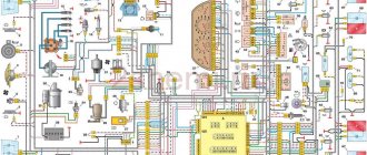
Electrical diagram of VAZ 2107, 21074
This page shows a color diagram of the electrical equipment of VAZ 2107, 21074 cars produced in 1988-2001 with a 37.3701 generator (with a built-in voltage regulator).
To enlarge the wiring diagram, click on the image below.
Electrical diagram of VAZ 2107, 21074 produced in 1988-2001 with generator 37.3701
- block headlights
- side direction indicators
- accumulator battery
- starter relay
- carburetor electro-pneumatic valve
- carburetor microswitch
- generator 37.3701
- gearmotors for headlight cleaners *
- Fan motor switch sensor
- engine cooling fan motor
- sound signals
- distributor
- spark plug
- starter
- coolant temperature gauge sensor
- engine compartment lamp
- low oil pressure warning sensor
- low brake fluid level indicator sensor
- windshield wiper motor
- carburetor electro-pneumatic valve control unit
- ignition coil
- headlight washer pump motor *
- windshield washer pump motor
- mounting block
- windshield wiper relay
- hazard warning and direction indicator relay
- brake light switch
- reverse light switch
- ignition relay
- ignition switch
- three lever switch
- hazard switch
- socket for portable lamp**
- heater fan switch
- additional resistor for the electric motor of the heater (stove)
- rear window heating indicator lamp
- low brake fluid level warning lamp
- signaling unit
- heater fan electric motor
- glove compartment lamp
- light switches on the front door pillars
- switches for warning lights of open front doors ***
- front door open warning lights ***
- connection block
- cigarette lighter
- watch
- instrument light switch
- diode for checking the serviceability of the low brake fluid level indicator lamp
- fuel level indicator
- fuel reserve indicator lamp
- speedometer
- turn signal indicator lamp
- carburetor choke indicator lamp
- battery charge indicator lamp
- carburetor choke warning switch
- instrument cluster
- econometrician
- light switches on the rear door pillars
- coolant temperature gauge
- tachometer
- parking brake indicator lamp ("handbrake")
- low oil pressure warning lamp
- high beam indicator lamp
- indicator lamp for turning on external lighting
- voltmeter
- parking brake indicator switch ("handbrake")
- outdoor light switch
- rear window heating switch with backlight
- rear fog light switch with on/off indicator *
- fog light circuit fuse
- lampshade ****
- tail lights
- level indicator and fuel reserve sensor
- connectors for connecting to the rear window heating element *
- license plate lights
In order to download the VAZ 2107 diagram and save it to your computer, hover over the image above, then right-click and select “save as image” (size about 300 kilobytes).
The image resolution is 1600×872 pixels, so the electrical circuit can be easily printed on a printer and used when repairing a car.
The order of conditional numbering of plugs in blocks:
- a - headlight units, headlight and windshield wipers, windshield wiper relay, carburetor solenoid valve control unit
- b - mounting block and three-lever switch
- c - hazard warning and direction indicator relay
- d — rear lights (numbering of pins in order from the edge of the board)
- d - hazard warning switch
Additional information "asterisks":
* — Installed on parts of manufactured cars.
** — Not installed since 2000.
*** - Not installed since 1998.
**** — Since 2000, instead of one lamp on the roof, two lamps have been installed on the door pillars.
parking lights
The dimensions on the VAZ-2107 are activated by the leftmost of the four key switches located under the gearbox control lever. This switch is a three-position switch: the side light, along with the license plate light and instrument lighting, is turned on in the second position.
The side lights are activated by a three-position switch located under the gearshift lever.
On the fuse block, which is located under the hood of the car near the windshield closer to the passenger seat, the rear side lights fuses are numbered F14 (8A/10A) and F15 (8A/10A). In this case, fuse F14 is responsible for the operation of the side lights of the left front headlight and the right rear light, as well as:
- a lamp indicating the operation of the dimensions;
- license plate lights;
- engine compartment light bulbs.
Fuse F15 is installed in the side light circuit of the right headlight and left rear light, as well as:
- instrument lighting;
- cigarette lighter lamps;
- glove compartment lighting.
If one of these lamps does not work, you should check the integrity of fuses F14 and F15.
Fuses F14 and F15 are responsible for the operation of the side lights.
Where is the reverse sensor located on a VAZ 2110 car?
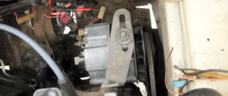
As already mentioned, this element is installed in the gearbox. This is logical: there is no need to install remote control rods. Why not on the gearshift lever? The sensor must record exactly the moment the gear is engaged, and not the change in the position of the control mechanisms. The exact location is the gearbox housing.
You can only find it while under the car: either in a hole or using a lift. It is screwed into the crankcase in the same way as an oil drain plug: using a threaded connection. The sensor is located horizontally, on the side wall of the gearbox, on the driver's wheel side. A connector and a signal wire are connected to it: there is no other such device in this area.
Where is it located and how to check it
To begin replacing the reverse sensor on a VAZ 2110, you must first determine its location.
Device location
But really, where is he? There is nothing difficult in finding this element.
- You will need a trestle or pit. One way or another, you should end up under the car.
- Now look towards the rear wheels of the car and raise your eyes to the gearbox. To the left of it is your desired sensor.
- Can it be confused with other devices? Hardly. Only for this element is provision for wiring from the gearbox. Therefore, you definitely won’t find other similar devices nearby.
Electrical diagram of VAZ 2107
Electrical diagram of VAZ 2107
1- block headlights; 2- side turn indicators; 3- battery; 4- starter switch relay; 5- carburetor electro-pneumatic valve; 6- carburetor microswitch; 7- generator 37.3701; 8- gear motors for headlight cleaners*; 9- electric motor switch sensor fan;10- electric motor of the engine cooling system fan;11- sound signals;12- ignition distributor;13- spark plugs;14- VAZ-21074 starter;15- coolant temperature indicator sensor;16- engine compartment lighting lamp;17- sensor low oil pressure indicator; 18 - low brake fluid level indicator sensor; 19 - windshield wiper gear motor; 20 - carburetor electro-pneumatic valve control unit; 21 - ignition coil; 22 - headlight washer pump electric motor*; 23 - windshield washer pump electric motor; 24 - mounting block; 25 - windshield wiper relay; 26 - hazard warning and turn signal relay; 27 - brake light switch; 28 - reverse light switch; 29 - ignition relay; 30 - ignition switch; 31 - three-lever switch; 32 - hazard warning switch; 33 - plug socket for a portable lamp**; 34 - heater fan switch; 35 - additional resistor for the heater electric motor; 36 - indicator lamp for turning on the rear window heating; 37 - indicator lamp for insufficient brake fluid level; 38 - indicator unit ;39- electric motor of the heater fan;40- glove box lighting lamp;41- lamp switch on the front door pillars;42- switch for open front door alarm lights***;43- open front door alarm lights***;44- connecting block ;45- cigarette lighter;46- VAZ-21074 clock;47- switch for instrument lighting;48- diode for checking the serviceability of the low brake fluid level indicator lamp;49- fuel level indicator;50- fuel reserve indicator lamp;51- speedometer;52 - indicator lamp for turning on the turn indicators; 53 - indicator lamp for closing the carburetor air damper; 54 - indicator lamp for charging the battery; 55 - switch for indicator for closing the air damper of the carburetor; 56 - instrument cluster; 57 - econometric indicator; 58 - lamp switches on the rear door pillars ;59- coolant temperature indicator;60- tachometer 21074;61- parking brake indicator lamp;62- insufficient oil pressure indicator lamp;63- high beam indicator lamp;64- exterior lighting indicator lamp;65- voltmeter;66 - parking brake indicator switch; 67 - exterior lighting lamp switch; 68 - rear window heating element switch with backlight lamp; 69 - rear fog light switch with on/off indicator*; 70 - fog lamp circuit fuse; 71 - ceiling lamp; 72 - rear lights VAZ 21074; 73 - level indicator and fuel reserve sensor; 74 - pads for connecting to the rear window heating element*; 75 - license plate lights.
Connection diagram of the VAZ 2107 mounting block
P1 — relay for turning on the heated rear window; P2 - relay for turning on the headlight cleaners and washer; P3 - relay for turning on sound signals; P4 - relay for switching on the electric motor of the engine cooling system fan; P5 - headlight high beam relay; P6 - low beam headlight relay; A - the order of conditional numbering of plugs in the mounting block blocks. The outer number with the letter “Ш” in the plug designation is the block number, and the inner number is the conventional number of the plug. The plugs of the blocks without color marking are conventionally shown in brown
Mounting block, without cover
1 — relay for turning on the heated rear window (P1); 2 — relay for turning on the headlight cleaners and washer (P2); 3 - relay for turning on sound signals (P3); 4 — relay for switching on the electric motor of the engine cooling system fan (P4); 5 - spare fuse; 6 — relay for turning on the high beam headlights (P5); 7 — relay for low beam headlights (P6); 8 - fuse
All images are taken from open sources and I do not claim authorship.
- Let's like!
- Subscribe!
- See you again!
Fuse numbering designation for KAMAZ vehicle
| Fuse markings | Rated current in Amperes | What is he responsible for? | Main power switch/ignition switch status |
| FU1.1 | 5A | EFU control unit | On / ON |
| FU1.2 | 5A | Air suspension control unit | On / ON |
| FU1.3 | 5A | Electrical Control Unit (CBCU) | On / ON |
| FU1.4 | 5A | EBS control unit | On / ON |
| FU1.5 | 5A | Engine control unit ADM3 | On / ON |
| FU1.6 | 10A | Neutralization system control unit | On / ON |
| FU1.7 | 10A | Engine control unit MR2 | On / ON |
| FU1.8 | |||
| FU1.9 | 10A | Retarder control unit | On / ON |
| FU1.10 | 5A | OBD diagnostic connector | On / ON |
| FU1.11 | 5A | Tachograph/instrument cluster | On / ON |
| FU1.12 | 5A | Connector for special add-ons | On / ON |
| FU2.1 | |||
| FU2.2 | 10A | Driver side control panel | On / ON |
| FU2.3 | |||
| FU2.4 | 5A | Generator field winding | On / ON |
| FU2.5 | 5A | Central locking control unit | On / ON |
| FU2.6 | |||
| FU2.7 | 5A | Sunroof control drive | On/ACC |
| FU2.8 | 20A | Air conditioner | On/ACC |
| FU2.9 | 15A | Driver side control panel | On/ACC |
| FU2.10 | 15A | Passenger side door control panel | On/ACC |
| FU2.11 | 5A | Audio system | On/ACC |
| FU2.12 | 10A | Cigarette lighter | On/ACC |
| FU3.1 | 15A | EBS control unit | On / 0 |
| FU3.2 | 15A | EBS trailer | On / 0 |
| FU3.3 | 15A | Air suspension control unit | On / 0 |
| FU3.4 | 15A | Dehumidifier | On / 0 |
| FU3.5 | |||
| FU3.6 | 10A | Retarder control unit | On / 0 |
| FU3.7 | 10A | Instrument cluster | On / 0 |
| FU3.8 | 20A | EFU control unit | On / 0 |
| FU3.9 | 10A | OBD diagnostic connector | On / 0 |
| FU3.10 | 10A | Electrical control unit | On / 0 |
| FU3.11 | 20A | Electrical control unit CBCU gr.4 | On / 0 |
| FU3.12 | 15A | EBS control unit | On / 0 |
| FU4.1 | 20A | Electric pump for raising/lowering the cab | On / 0 |
| FU4.2 | 10A | Interior lighting | On / 0 |
| FU4.3 | 10A | Connector for special add-ons | On / 0 |
| FU4.4 | 5A | Power supply for keys and sensors | On / 0 |
| FU4.5 | 10A | Audio system | On / 0 |
| FU4.6 | 10A | Heated glass | On / 0 |
| FU4.7 | 10A | Hitch light | On / 0 |
| FU4.8 | 10A | 24V socket | On / 0 |
| FU4.9 | 10A | Sound signal | On / 0 |
| FU4.10 | 5A | Battery remote switch relay | On / 0 |
| FU4.11 | |||
| FU4.12 | |||
| FU5.1 | 15A | Heating fuel in the fuel intake | Doesn't depend / 0 |
| FU5.2 | 15A | Fuel heating in FGOT | Doesn't depend / 0 |
| FU5.3 | |||
| FU5.4 | 5A | Tachograph | Doesn't depend / 0 |
| FU5.5 | 10A | Engine control unit ADM3 | Doesn't depend / 0 |
| FU5.6 | 15A | Neutralization system control unit | Doesn't depend / 0 |
| FU5.7 | 20A | Electrical control unit CBCU gr.1 | Doesn't depend / 0 |
| FU5.8 | 20A | Electrical control unit CBCU gr.2 | Doesn't depend / 0 |
| FU5.9 | 20A | Electrical control unit CBCU gr.5 | Doesn't depend / 0 |
| FU5.10 | 20A | Electrical control unit CBCU gr.6 | Doesn't depend / 0 |
| FU5.11 | 25A | PZD | Doesn't depend / 0 |
| FU5.12 | |||
| FU6.1 | 15A | Electrical control unit MUX4-P | Doesn't depend / 0 |
| FU6.2 | 15A | Electrical control unit MUX4-P | Doesn't depend / 0 |
| FU6.3 | 15A | Electrical control unit MUX4-P | Doesn't depend / 0 |
| FU6.4 | 15A | Electrical control unit MUX4-P | Doesn't depend / 0 |
| FU6.5 | 15A | Electrical control unit MUX4-P | Doesn't depend / 0 |
| FU6.6 | 15A | Electrical control unit MUX4-P | Doesn't depend / 0 |
| FU6.7 | 15A | Heated seat | Independent/ON |
| FU6.8 | |||
| FU6.9 | 15A | Central locking control unit | On / 0 |
| K1 | Wiper mode relay | ||
| K2 | Windshield wiper brake relay | ||
| K3 | Hitch light relay | ||
| K4 | Horn relay | ||
| K5 | Fuel heating relay | ||
| K6 | Cab tilt lock relay | ||
| K7 | Battery cut-off relay | ||
| K8 | Air conditioner relay |
58 most important apple watch features. full list
Sensor diagnostics
First of all, an external inspection is carried out. We check the integrity of the wiring and the condition of the contact group. It is better to test the wiring with a multimeter from the removed connector to the nearest input into the car's distribution contact box. Next, we test the sensor itself:
- We put the car on a pit or on a lift.
- Disconnect the connector and move it to the side.
- Turn on the ignition without starting the engine.
- We connect the multimeter probes to the sensor and ask an assistant to engage reverse gear.
- A working sensor will show zero resistance between the contacts.
If the test fails, the sensor must be removed from the transmission. In this case, some of the transmission oil will leak out of it, so it is better to prepare a plug in the form of a bolt with the same thread or temporarily screw in another sensor.
Tip: Do not throw away the broken sensor; it may be useful for temporarily closing the hole.
After washing the outside of the housing and cleaning the contacts, you can check the sensor with the same multimeter. The pressing force on the rod is small, provided that it is not blocked by corrosion. Therefore, just press it with your finger and look at the results of measuring the resistance.
Methods for troubleshooting
Troubleshooting is not a complicated process and even novice car enthusiasts can do it (the author of the video is Avtoelektika VC).
First of all, you should check the integrity and condition of the wiring.
Using a multimeter, you need to test the wiring. Damaged or torn sections should be replaced intact or soldered. If there are traces of oxidation processes on the contacts, they need to be cleaned.
If the LEDs burn out, they need to be replaced in pairs. If the breaker fails, it must be replaced with a new one, as it cannot be repaired. Before replacing, turn off the vehicle's power by removing the negative terminal from the battery. Then disconnect the power wires from the breaker. Next, you need to loosen the lock nut and unscrew the main nut securing the switch to the bracket.
What to do if there is no charge, weak charge (battery is discharged)?
If the battery of your VAZ 2107 is discharged, then one of three elements may be “to blame”: the generator, the voltage regulator, and the connections between them. Determining “who is to blame” can be very simple, even without additional devices. How this article will help.
We carry out testing using standard equipment
To monitor the operation of the generator on the “seven” there are two instruments: a voltmeter and a control light on the instrument panel. With their help, you can track the cause of your troubles.
1) Turn on the ignition without turning on the starter
and look at the warning light. It should shine at full intensity, as in the photo. The voltmeter needle, normally, stands on the white part of the scale (photo). Let's say everything is OK - go to point 2 - start the engine.
The battery charge control lamp is on
Position of the voltmeter needle before starting the engine (ignition on)
The lamp does not light, the voltmeter needle remains at zero when the ignition is turned on.
Check fuse No. 10 in the mounting block. 99% of the time it will be burnt out. In this case, all other lamps on the instrument panel will also be de-energized. Replace it with the same one and test again. If the fuse burns out again, you need to look for the cause, that is, a short circuit. We check whether the wires from the generator are disconnected, whether the insulation is frayed somewhere, etc. Diagram 3 at this link will help you find the reason
The lamp does not light up, the voltmeter needle shows normal
We check the wires on the generator to see if the wire has come loose from terminal “61”. If everything is normal there, you need to check whether there is a “plus” on this wire using a test lamp, an indicator screwdriver or a multimeter.
Terminal “61” of the VAZ-2107 generator
If there is a “plus”, we check the “tablet” (aka “chocolate”) and the generator.
There is no “plus” - you will have to remove the instrument panel and check the lamp. Replace the burnt out one. How to remove the panel, watch the video
2) Start the engine
The control lamp should go out, the voltmeter needle goes into the green sector and is located from the middle to the right edge (photo). If everything is so, then most likely the generator is working normally.
The voltmeter shows normal voltage (charging is present)
The lamp remains on or dims slightly
If you give it gas, it goes out at high speeds and lights up again when they decrease. The voltmeter needle is in the white sector and goes to the edge of the green when the speed increases. The generator output is faulty. The same conclusion if the lamp continues to light at any speed, and the voltmeter needle is in the white sector and even goes to red.
Voltage too low (motor running). Weak charge
Read, it may come in handy: If the electric motor of the heater (stove motor) of the VAZ-2107 does not work
3) If the generator seems to be working, but the battery is gradually discharged
Let's do one more check. We start the engine, turn on the heater fan and low beam, take the key to “10” and, loosening the negative terminal of the battery, remove it. An idling engine (about 900 rpm) should not stall. If the engine stops, put the terminal back in place and start it again. While holding the speed at 1200-1500, remove the terminal again. Has the engine stalled again? Then turn off the headlights, leave the heater fan on and repeat the test. Now the engine with the negative terminal disconnected from the battery continues to run. The generator output works, but does not produce the required current; it needs to be repaired.
Note! During such a check, it is better and safer to work together. Do not disconnect the battery terminal without at least turning on the heater fan or other load.
A voltage surge at the time of shutdown can “burn” the electronic elements of ignition systems
You need to be especially careful on a car with an injection engine.
Replacing the sensor
And now it’s time to consider the process of replacing the reverse sensor on various VAZ cars - from 2106 to 2115. Here are the instructions.
VAZ 2107
Let's start with the Classics
Let's start with the VAZ 2107 car. On VAZ Classic models everything is done exactly the same.
Advice! Before replacing the sensor on any car, clean the gearbox housing from dirt to make it easier to find the sensor and to prevent dirt from getting into the oil.
First, we look for the sensor - it is located on the right side of the gearbox, if you look at the car as it moves. It is very difficult to make a mistake - this is the only part in the gearbox where two wires fit.
Sensor location on Classic
- If the wires are broken, then look for protruding contacts.
- If the wires are still on the sensor, then disconnect them.
- Next, you will need a 22 key. They need to unscrew the sensor. For convenience, it is better to take a longer wrench, since over time the sensor will stick to the crankcase.
- If you cannot unscrew the reverse sensor using a wrench (head), then you need to do this using a hammer and chisel.
Note! The gearbox housing is very fragile. Therefore, be extremely careful not to damage it with hammer blows.
- Then clean the seat from dirt using a knife.
- Remove the metal washer along with the dirt and replace it with a new one.
- Insert the sensor and tighten it using the same wrench until it stops.
- Next you need to put the wires back on. If necessary, crimp the contacts with pliers.
- And now, the replacement of the reverse sensor on the VAZ 2107 is completed!
Some people have a question about oil - whether it will leak or not. In this case it will not leak.
VAZ 2109
VAZ 21099 replacement reverse sensor
Let us remind you that this point applies to the Samara family as a whole, and not just to the VAZ 2109 car:
- Remove the protection from the car engine, if any.
- The location of the sensor on a VAZ 2108 and similar cars is slightly different than on a Classic, since the car has front-wheel drive.
- As the vehicle moves, the sensor is located on the left side.
- If the Classic had to be driven into a viewing hole, then cars with front-wheel drive can simply be lifted under the left front wheel using a jack.
- Again, the electrical wiring leads to the sensor.
- Remove the wires.
- To remove the sensor you will need an extended 22mm socket and a wrench.
- Using the head, remove the sensor.
VAZ 2109 replacement of reverse sensor
Remember! Replacing a reverse sensor on a front-wheel drive vehicle is characterized by small oil leaks from the gearbox housing.
- Prepare a container and, as soon as you unscrew the sensor, place it so that the oil does not spill on the floor.
- Insert the new sensor as quickly as possible.
- Screw it in by hand first and then tighten it using the same socket and ratchet.
- Connect the electrical wiring wires.
- Add the required amount of oil.
VAZ 2110
Cars of the VAZ 2110 family are equipped with engines from the VAZ 2108. Therefore, there is no point in writing the same information a second time. The answer is: VAZ 2110 replacement of the reverse sensor - see the information above.
VAZ 2114
Replacing the reverse sensor on a VAZ 2114 or cars of the Samara-2 family. Instructions:
- The essence of the process is the same.
- Raise the car using a jack.
- If necessary, remove the engine protection, but this may not even be necessary.
- Find the sensor; on new gearbox models of Samara-2 models it has a slightly different location, but finding it will also not be difficult.
- Disconnect the electrical wiring connector from the sensor.
- Using a 22mm wrench (it’s more convenient to use a head, but you can also use a wrench) unscrew the sensor.
- Before removing the sensor from the connector, place an oil container.
https://youtube.com/watch?v=xOtdxaYfO1M
Note. It is best to replace the sensor on a cold car, as less oil will leak out. Although this is not important.
- Take out the old sensor and insert the new one along with a new ring.
- Screw the sensor using a wrench or socket.
- Wipe the gearbox housing from oil traces.
- Connect the wires.
- Top up the oil level in the gearbox to the required level.
- Reinstall the engine protection (if necessary).
So, the sensors have been changed. Now you can start checking their functionality.
Reverse Controller Replacement Guide
Before replacing, it is best to make sure that the sensor is really faulty and you need to buy a new one.
To diagnose, you need to do the following:
- lift the car and leave it on supports;
- find the sensor on the gearbox (crankcase) and engage reverse gear;
- check continuity between terminals 1-3 and 2-4 in reverse gear and then in neutral;
- There should be no conductivity in the gearbox, as well as in other positions.
First you need to lift the car and remove the negative terminal from the battery. Then drain the oil and remove the protection from the crankcase. Near the gearbox there is the necessary regulator. It is necessary to disconnect its block from the gearbox, then unscrew the clamping bolt that holds the regulator in the crankcase. It looks a bit like a spark plug. The regulator has a wire and a button that closes the contacts.
Functionality check
If a breakdown is detected, you need to check:
- switch on sensor;
- switching wiring.
Frog sensor
The following algorithm is used:
- Place the car on a viewing hole or overpass.
- Stop the engine and secure the vehicle with the parking brake or wheel chocks.
- Inspect the gearbox housing; the sensor is located on the rear wall. On some of the units nearby, a speed detection sensor is installed, which transmits a signal to the electronic speedometer.
- Remove the plug from the sensor connector and inspect the contacts.
- Using a piece of wire or a paper clip, close the metal elements inside the block.
- Turn on the ignition circuit. If the wiring is in good condition, the warning lights should light up.
To test the sensor, a lamp rated for 12 V is used, installed in a socket with patch cables. The indicator is connected to the sensor terminals when reverse gear is engaged and the ignition is active. If the lamp does not turn on, the sensor needs to be replaced or adjusted.
Circuit integrity
To test the continuity of the circuit, use a multimeter set to cable testing mode. When checking the wires, be sure to remove the flashlight or dismantle the cover, which allows you to get to the contact pad of the lamp. The device is connected to the beginning and end of the wire; if the circuit is closed, a buzzer sounds. You can use a control light with a battery that is connected through a wire running from the sensor to the lamp. The damaged wire must be replaced with a copper stranded cord with the appropriate cross-section.
Adjusting the gearbox switch
Some machines provide the ability to adjust the position of the sensor depending on the location of the shift knob. There is a lock nut on the sensor body that needs to be loosened. Then the reverse speed is switched on, and a warning lamp is hung on the sensor contacts. The housing is screwed into the box housing until the contacts are closed and power is supplied to the thread. The sensor is fixed in the found position with a lock nut, and then the electrical wiring plug is connected.
On automatic transmissions there is a reverse sensor combined with a neutral or parking position indicator. Additional indication is necessary to allow the engine to start only when the kinematic chain is open. A similar design is used on some transmissions; there is also a switch in the selector that cannot be adjusted.
Brief algorithm for setting up the sensor:
- Remove the plug and determine the purpose of the contacts according to the markings or electrical diagram of the car.
- Turn on the ignition and move the selector lever to the reverse gear position.
- Rotate the sensor until the signal lights turn off and mark the position of the sensor body relative to the crankcase with chalk marks. To check, a test lamp with an external power source is used, which is connected to the reverse contacts.
- Connect the lamp to the remaining contacts and slowly tighten the housing until the filament turns on. Mark the position with chalk on the sensor housing and the box housing.
- Set the switch to an intermediate position between the found positions. With correct adjustment, when the lever is moved to position R (reverse movement), the lighting equipment at the rear of the machine will turn on, and in positions P and N it will be possible to start the engine.