Colored wiring diagrams for the VAZ 2110 (injector and carburetor engine) are provided with a description of all elements for various modifications. The information is intended for self-repair of the car. Electrical circuits are divided into several blocks for ease of viewing via a computer or smartphone; there are also circuits in the form of a single picture with a description of the elements - for printing on a printer in one sheet.
There are two types of electrical wiring for the VAZ-2110: carburetor and injector. There are slight differences, but the basic principles of operation and wiring are the same. Depending on the location, the wiring differs into: under the hood and in the cabin. All electrical equipment of the car is connected using wires of a certain color. Each element has its own wiring harness through the blocks and fuses.
VAZ 2110 - modifications
VAZ-21100 . The base model which was produced from 1996 to 2000. The car was equipped with an 8-valve carburetor VAZ-21083 engine with a displacement of 1.5 liters and a power of 69 horsepower.
VAZ-21101 . This modification has been produced since 2004, equipped with an 8-valve gasoline injection engine with a displacement of 1.6 liters.
VAZ-21102. Like the previous modification with an 8-valve injection engine, but with a volume of 1.5 liters.
VAZ-21103 . Modification of the “tens” with a 16-valve injection engine with a working volume of 1.5 liters.
VAZ-21103M . A restyled modification of the VAZ-21103, equipped with a 16-valve petrol injection engine with a displacement of 1.5 liters and a power of 92 horsepower. Produced since 2002.
VAZ-21104 . The modification is equipped with a 16-valve petrol injection engine with a working volume of 1.6 liters.
VAZ-21104M . A restyled modification of the VAZ-21104, equipped with a 16-valve petrol injection engine with a displacement of 1.6 liters. Produced since 2004.
VAZ-21106 GTI . The engine of the VAZ-21106 GTI is the most powerful and expensive modification that has been produced since 2000. The car was equipped with a 2-liter 16-valve Opel C20XE gasoline engine with a capacity of 150 horsepower. The car was fitted with a body kit with swollen arches, and the track was widened by 76 millimeters. It was equipped with R15 wheels with low-profile tires.
VAZ-21106 Coupe . Coupe VAZ-21106 in a coupe body. A distinctive feature of the car was the presence of only two doors, which were lengthened by 250 millimeters, while the body was shortened by 170 millimeters. The engine was installed the same as in the previous VAZ-21106 GTI model.
VAZ 21106 WTCC . A sports modification of the 106 model, it participated in the 2008 FIA WTCC international championship.
VAZ 21107 . Modification of a car for rally competitions. It was equipped with a welded safety cage and a different suspension design.
VAZ 21108 "Premier" . A modification with a body lengthened by 170 millimeters in the rear door area, which provided more convenient entry and exit of passengers. It was equipped with a 1.5-liter injection 16-valve engine.
VAZ 21109 “Consul” . 4-seater luxury limousine based on the VAZ-2110 car. In addition to the length of the body, the dimensions of the rear door were also increased, for more convenient entry and exit of passengers. Equipped with a 1.5 liter engine and R14 or R15 wheels. Overall dimensions: length - 4950 mm, width - 1700 mm, height - 1440 mm. Fuel consumption in the urban cycle is 9.5 liters per 100 kilometers.
VAZ 2110-91 . Modification of the VAZ-2110 with a 1308 cm3 rotary piston engine. The car could reach speeds of up to 240 km/h, and acceleration from 0 to 100 km/h took 6 seconds.
A car with a 16-valve injection engine in the Gran Lux configuration includes:
- Electric windows;
- Door locking;
- Trunk lock lock;
- Velvet seat upholstery;
- Immobilizer;
- Heated front seats;
- Ventilated 14-inch brake discs;
- Rear spoiler with additional brake light;
- Fog lights.
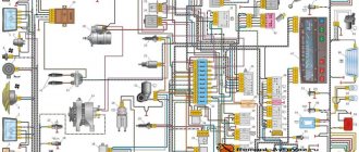
Wiring diagram for VAZ 2110 carburetor
In the instrument panel wiring harness, the second ends of the wires of white, black, orange, white with a red stripe and yellow with a blue stripe are connected to each other at the same points. The bends of the wires at the points of entry into the harness indicate the direction of their laying in the bundle.
See the complete diagram in one file below (click to enlarge):
1 – headlight 37 – instrument cluster 2 – front brake pad wear sensor 38 – rear fog light switch 3 – fan motor switch 39 – fog light indicator lamp 4 – engine cooling system fan electric motor 40 – rear window heating indicator lamp 5 – sound signal 41 – clock 6 – generator 42 – rear window heating switch 7 – oil level sensor 43 – steering column switch 8 – carburetor solenoid valve control unit 44 – block for switching wires when installing headlights of another type 9 – heater controller 45 – switch instrument lighting 10 – recirculation valve switch 46 – ignition switch 11 – illumination lamp for heater control levers 47 – connectors for connecting the headlight cleaner wiring harness 12 – switch 48 – socket for a portable lamp 13 – carburetor limit switch 49 – directional light 14 – control sensor oil pressure lamps 50 – brake light switch 15 – spark plugs 51 – interior lamp 16 – carburetor solenoid valve 52 – on-board control system unit 17 – coolant temperature indicator sensor 53 – fuel level indicator sensor 18 – ignition distributor 54 – hazard warning switch 19 – ignition coil 55 – driver’s seat belt sensor 20 – starter 56 – cigarette lighter 21 – heater fan motor 57 – ashtray backlight lamp 22 – additional resistor for heater motor 58 – glove compartment light switch 23 – speed sensor 59 – connector for on-board computer 24 – reverse light switch 60 – glove box lighting lamp 25 – micromotor gearbox for heater flap drive 61 – side turn signal 26 – recirculation valve 62 – switch in the front door pillar 27 – brake fluid level sensor 63 – switch in the rear door pillar 28 – pads for connecting the rear window washer motor 64 – parking brake warning lamp switch 29 – battery 65 – trunk light 30 – windshield washer motor 66 – interior air temperature sensor 31 – washer fluid level sensor 67 – external rear light 32 – level sensor coolant 68 – internal rear light 33 – windshield wiper motor 69 – license plate light 34 – mounting block 70 – block for connecting the rear window heating element 35 – blocks for connecting the warning light harness 71 – block for connecting an additional brake signal 36 – outdoor light switch
Diagram of VAZ 2110 injector 8 valves
1 – headlight 2 – front brake pad wear sensors 3 – horn 4 – cooling system fan 5 – reverse light switch 6 – battery 7 – generator 8 – oil pressure warning lamp sensor 9 – oil level sensor 10 – spark plugs 11 – injectors 12 – idle speed control 13 – electronic control unit blocks 14 – throttle position sensor 15 – crankshaft position sensor 16 – ignition module 17 – coolant temperature indicator sensor (for instrument cluster) 18 – starter 19 – diagnostic block 20 – coolant temperature sensor (for the engine management system) 21 – speed sensor 22 – fuel pump switch relay 23, 35, 39 – fuses 24 – electric fuel pump 25 – micromotor gearbox for heater damper drive 26 – recirculation valve 27 – heater fan 28 – windshield washer pump windows 29 – washer fluid level sensor 30 – brake fluid level sensor 31 – coolant level sensor 32 – windshield wiper gear motor
33 – additional heater fan resistor 34 – injection system power supply relay 36 – canister purge valve 37 – mass air flow sensor 38 – cooling system fan activation relay 40 – external lighting switch 41 – knock sensor VAZ-2110 injector 42 – oxygen concentration sensor ( heated lambda probe) 42* – CO potentiometer (installed on cars running on leaded gasoline; in this case, an oxygen concentration sensor is not installed) 43 – fog light indicator lamp 44 – rear window heating indicator lamp 45 – fog light switch 46 – rear window heating switch 47 – instrument cluster 48 – mounting block 49 – fuel level sensor 50 – ignition switch 51 – instrument backlight brightness control 52 – steering column switch 53 – heater control lever illumination lamp 54 – hazard warning switch 55 – electronic heater control unit; 56 – recirculation valve switch 57 – on-board control system display unit 58 – side direction indicators 59 – temperature sensor for the heating system 60 – interior lamp 61 – front interior lamp 62 – socket for a portable lamp 63 – electronic clock 64 – switches in the racks front doors 65 – switches in the rear door pillars 66 – glove compartment lighting lamp 67 – glove compartment lighting switch 68 – cigarette lighter 69 – ashtray lighting lamp 70 – brake light switch 71 – rear window heating element 72 – external rear lights 73 – internal rear lights 74 – license plate lamps 75 – trunk lighting lamp
See the complete diagram in one file below (click to enlarge):
Why the sound signal does not work on the VAZ-2112 photo and video
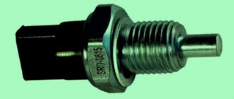
Lada 2110 Logbook Replacing the thermoelement of the VAZ 2110 thermostat
Operating a car with a faulty sound signal is prohibited. At the same time, on cars of the “tenth” family, the horn may stop working for no apparent reason. Potential “+12” is connected to one of the horn wires. And the second terminal should close to ground when the key is pressed. Let's look at why the signal on the VAZ-2112 does not work, and for this we will check the control points.
Sometimes it is possible to restore contact with ground without removing the steering wheel. An example is shown in the video.
Features of the VAZ-2112 electrical circuit
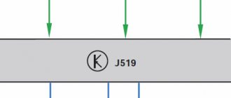
The owners of cars of the “tenth” family are to some extent lucky: there is no relay in the horn circuit, but only a switch. The proof is given below.
Standard wiring diagram
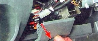
The first step is to check fuse F7. In the mounting block it is in the top row (seventh from the left).
Voltage “+12” is applied to one of the fuse terminals. Check it out!
If the fuse is good, potential “+12” should be at one of the horn terminals. Let's take a look under the hood...
Audio module connector
Disconnect the connector and check both terminals with a tester. We connect the second probe of the voltmeter to the negative of the battery.
The standard reason why the signal does not work on the VAZ-2112 is this: the “positive” voltage is connected, but the contact with the “ground” is broken. Most often the problem lies in the switch.
We diagnose the sound signal
It all starts with the connector pins:
- Let's say the voltage “+12” is not caused on both contacts. Then look for a short circuit or break point, starting from terminal 6-Ш5 (diagram above).
- If positive voltage is received, check the second terminal. It will contact ground when you press the horn button. During this check, the battery must be disconnected.
- If the previous two steps are completed successfully, then voltage is supplied to the horn. It may need to be replaced or the contacts cleaned.
By the way, in “step 2” it is recommended to rotate the steering wheel - contact may be broken at certain angles of rotation.
Removing the steering wheel
If “step 2” is not successful, you need to remove the steering wheel. The two copper strips should “close” when pressed - everything is clear here. The test is carried out with an ohmmeter, and if necessary, the switch is replaced.
Steering wheel after dismantling
When the steering wheel is removed, you can clean the contact tracks. The wire contacts in the column must also be clean.
Dismantling from start to finish
First you need to unscrew the two screws under the trim. Having removed the plastic, you can see the contact plate - perhaps that was the problem.
First step in dismantling
Try cleaning the contacts and performing “step 2” again. If there is no result, take a 24mm wrench and unscrew one nut (not all the way).
The steering wheel needs to be knocked off its splines
The steering wheel is pushed towards itself. And then the nut can be unscrewed completely.
When installing, follow one rule. The protrusion on the bracket should fit into the slot made in the plastic ring (see photo).
Steering wheel installation (first step)
How to remove a faulty signal (horn)
There is a single module mounted under the radiator grille. To remove it, unscrew one nut (key “13”). First disconnect the connector.
Dismantling, adjustment before installation
It will be necessary to remove the grille. This action is difficult to perform on both the “Ten” and even on the VAZ-2112, and the signal may not work due to faulty wiring. First achieve what was discussed in “step 3”. And only then, if necessary, proceed with replacement.
One adjusting screw is fixed to the horn body. Set it to the middle position and check.
Removing the radiator grille
- Taking the “10” key, unscrew the two screws on top (as in the photo).
You can't remove the grill right away. Self-tapping screw for radiator grille fastening - Using both hands, applying equal force on both sides, pull the grill upward.
In this case, the two lower clamps should not break. An important fastening element is the clamp. - Installation will be easier - there is no risk of breaking the clamps.
The article number of the new radiator grille is 2110-8401014 (or 8401614, or 8401714).
Diagram of VAZ 2110 injector 16 valves
1 - headlight 35 - instrument lighting switch 2 - front brake pad wear sensors 36 - ignition switch 3 - reverse light switch 37 - mounting block 4 - engine cooling fan electric motor 38 - recirculation valve switch 5 - sound signal 39 - controller heater 6 - right front door locking motor 40 - hazard warning switch 7 - power window relay 41 - heater control lever illumination lamp 8 - 8 A fuse 42 - glove compartment lighting lamp 9 - starter 43 - glove compartment lighting lamp switch 10 - battery 44 - cigarette lighter 11 - generator 45 - on-board control system display unit 12 - windshield washer motor 46 - ashtray lighting lamp 13 - washer fluid level sensor 47 - brake signal switch 14 - left front door locking motor 48 - locking motor left rear door 15 — power window switch of the left front door 49 — power window switch of the left rear door 16 — coolant level sensor 50 — power window motor of the left rear door 17 — windshield wiper motor 51 — socket for a portable lamp 18 — recirculation valve 52 — clock 19 - micromotor gearbox for heater flap drive 53 - gearmotor for electric window lift on the right rear door 20 - electric motor for heater 54 - power window switch at the right rear door 21 - trunk lock switch 55 - gearmotor for locking the right rear door 22 - power window switch at the right front door 56 - side turn signal 23 - electric window motor of the right front door 57 - parking brake warning lamp switch 24 - door lock system control unit 58 - driver's seat belt sensor 25 - additional heater motor resistor 59 - directional light bulb 26 - brake fluid level sensor 60 - interior light bulb 27 - electric window motor of the left front door 61 — interior air temperature sensor 28 — exterior lighting switch 62 — switch in the front door pillar 29 — instrument cluster 63 — switch in the rear door pillar 30 — rear fog light switch 64 — external rear light 31 — warning lamp fog light 65 - interior rear light 32 - rear window heating indicator light 66 - license plate lights 33 - rear window heating switch 67 - trunk light 34 - steering column switch A - blocks for connecting the rear window washer motor B - blocks for connecting the harness injection system C - to the warning light harness block D - block for connection to the on-board computer E - to the headlight cleaner harness block F - block for connection to the fuel level sensor in the electric fuel pump module G - to the rear window heating element H - block for connecting an additional signal braking J - to the trunk lock motor
Useful: VAZ speed sensor pinout and DS connection diagram
See the complete diagram in one file below (click to enlarge):
Electrical circuit of ECM VAZ-21101
1 — VAZ-21101 controller; 2 — block of the ignition system harness to the ABS cabin group harness; 3 — diagnostic block; 4 — immobilizer warning sensor; 5 — immobilizer control unit; 6 — ignition coil; 7 — spark plugs; 8 — nozzles; 9 — electric fuel pump; 10 — block of the ignition system harness to the fuel level sensor harness; 11 — block of the fuel level sensor harness to the ignition system harness; 12 — block of the ignition system harness to the injector harness; 13 — injector harness block to the ignition system harness; 14 — speed sensor; 15 — idle speed regulator; 16 — throttle position sensor; 17 — coolant temperature sensor; 18 — mass air flow sensor; 19 — oil pressure warning lamp sensor; 20 - phase sensor; 21 — oxygen sensor; 22 — crankshaft position sensor; 23 — knock sensor; 24 — solenoid valve for purge of the adsorber; 26 — coolant temperature indicator sensor; 27 — block of the ignition system harness to the instrument panel harness; 28 — block of the instrument panel harness to the ignition system harness; 29 — controller power supply fuse; 30 - ignition relay; 31 - ignition relay fuse; 32 — fuse for the electric fuel pump power supply circuit; 33 — electric fuel pump relay; 34 — electric fan relay; 35 — ignition system harness block to the air conditioner connector; 36 — block of the ignition system harness to the side door harness. 37 — electric fan of the cooling system; 38 — diagnostic connector; 39 — ignition switch; 40 — instrument cluster; 41 — on-board control system unit; 42 — starter relay; 43 — contacts of the 8-terminal blocks of the instrument panel harness and the front harness; 44 — contacts of the 21-terminal blocks of the instrument panel harness and the rear harness; 45 - trip computer.
- A - to the “plus” terminal of the battery;
- B1 — grounding point of the fuel level sensor harness;
- B2, B3 — grounding points of the ignition system harness;
- C - to the starter;
- D - to the driver's door interior lamp switch.
Engine control circuit VAZ-21102, 21103
Engine control circuit for VAZ-21102, VAZ-21103 (controller M1.5.4N, “January-5.1”).
1 - injectors 2 - spark plugs 3 - ignition module 4 - diagnostic block 5 - controller 6 - block connected to the instrument panel wiring harness 7 - main relay 8 - fuse connected to the main relay 9 - electric fan relay 10 - fuse connected to electric fan relay 11 – electric fuel pump relay 12 – fuse connected to the electric fuel pump relay 13 – mass air flow sensor 14 – throttle position sensor 15 – coolant temperature sensor 16 – idle speed regulator 17 – VAZ-21102 oxygen sensor 18 – knock sensor 19 – Crankshaft position sensor 20 – canister purge solenoid valve 21 – immobilizer control unit 22 – immobilizer status indicator 23 – vehicle speed sensor 24 – electric fuel pump with fuel level sensor 25 – oil pressure warning lamp sensor 26 – coolant temperature indicator sensor 27 – level sensor oil 28 - phase sensor (installed on a car with a 16-valve engine) A - block connected to the wiring harness of the anti-lock brake system (ABS) B - block connected to the air conditioner wiring harness C - block connected to the electric fan wiring harness D - wires , connected to the ignition switch (backlight lamp) E - block connected to the blue-white wires disconnected from the ignition switch (when installing the immobilizer) F - to the “+” terminal of the battery G1, G2 - grounding points The diagram uses the designation of the element number circuit to which this wire is connected, for example “-4-”. In some cases, in addition to the designation of the element number, it is given through an oblique fraction and the contact number, for example “-5/15-”. The diagram does not show the connection points of the pink-black, red and green with a red stripe wires.
Pinout of 8-pin connector
- power supply
- speed sensor (electric speedometer)
- fuel consumption (for BC)
- coolant sensor
- emergency oil pressure
- check lamp
- oil level sensor
- tachometer signal
Standard version of the brake light operating diagram
Power is supplied to fuse F17 from the battery, then the current goes to limit switch contact 11, and then, if the limit switch is closed, a circuit is formed with the filament of lamps 7. But note: part of the circuit is relay K1, more precisely, its contacts 5 and 4.
Basic network diagram
If the brake lights do not light up, on the VAZ-2112, as on all Tens, check one fuse. It is called F17 and is located in the mounting block to the left of the driver.
Main mounting block
It is important to know: voltage is always present at one of the fuse terminals. Check it out!
A few words about the “serviceability relay”
The lamp health relay is called K1, and it is the largest in the mounting block. If you remove this relay, then when you press the pedal you can dial the voltage at terminal 5 (but not 4). Look at the diagram again, and it will become clear what we are talking about.
The largest relay in the block
All relay contacts are numbered. Check the voltage at the block terminals:
- 6
– “mass” potential; - 2
– voltage “+12”, but only after turning on the ignition; - 5
– “+12” by pressing the pedal; - 4
– the terminal rings like a ground tap.
If the potential “0” is not generated at terminal “4,” it means that the lamp filaments are burnt out or there is a break in the wiring. Now consider something else: the ground potential has been detected, but the lamps do not light. This is where suspicions of a short circuit arise.
Electrical circuit of ECM VAZ-21104
1 — block of the ignition coil wiring harness to the ignition system harness; 2 — block of the ignition system harness to the ignition coil wiring harness; 3 — ignition coils VAZ-21104; 4 — immobilizer warning sensor; 5 — immobilizer control unit; 6 — spark plugs; 7 — nozzles; 8 — diagnostic block; 9 — block of the ignition system harness to the ABS cabin group harness; 10 - controller; 11 — electric fuel pump; 12 — block of the ignition system harness to the fuel level sensor harness; 13 — block of the fuel level sensor harness to the ignition system harness; 14 — block of the ignition system harness to the injector harness; 15 — injector harness block to the ignition system harness; 16 — block of the ignition system harness to the side door harness; 17 — speed sensor; 18 — idle speed regulator; 19 — throttle position sensor; 20 — coolant temperature sensor; 21 — mass air flow sensor; 22 — oil pressure warning lamp sensor; 23 - phase sensor; 24 — oxygen sensor; 25 — crankshaft position sensor; 26 — knock sensor; 27 — solenoid valve for purge of the adsorber; 28 — oil level sensor; 29 — coolant temperature indicator sensor; 30 — block of the ignition system harness to the instrument panel harness; 31 — block of the instrument panel harness to the ignition system harness; 32 — ignition relay; 33 - ignition relay fuse; 34 — fuse for the electric fuel pump power supply circuit; 35 — electric fuel pump relay; 36 — electric fan relay; 37 — controller power supply fuse; 38 — ignition system harness block to the air conditioner connector; 39 — instrument cluster; 40 — ignition switch; 41 — electric fan of the cooling system; 42 — on-board control system unit; 43 — starter relay; 44 — contacts of the 8-terminal blocks of the instrument panel harness and the front harness; 45 — contacts of the 21-terminal blocks of the instrument panel harness and the rear harness; 46 — trip computer; 47 - diagnostic connector.
- A - to the “plus” terminal of the battery;
- B1 — grounding point of the ignition coil wiring harness;
- B2 — grounding point of the fuel level sensor harness;
- B3, B4 - grounding points of the ignition system harness;
- C - to the starter;
- D - to the driver's door interior lamp switch.
According to the scheme described above, fuel regulation in a car is carried out. Moreover, it depends not only on the load of the valves in the engine, but also on the corresponding position relative to the throttle valve. With the help of a diagram of electrical wiring and valves, it is possible to understand which of the relays or fuses is malfunctioning and replace it in time. In this case, one of the main roles when supplying fuel is played by electrical equipment (controllers) that regulates the operation of the injector.
Self-installation of a signal from the Volga on a VAZ
Lada 2105 Bright White 15 R Logbook Installation of steering column switches Chevrolet Niva ignition switch VAZ 2110
Most models developed by VAZ, including the widely used VAZ 2108, VAZ 2109 and VAZ 21099 today, are equipped with not very euphonious sound signals, which often upsets the owners of these cars. Meanwhile, nowadays there are quite a lot of quite worthy replacements for the standard VAZ signal and, in particular, the option of installing an excellent sound signal from the Volga can be an excellent alternative.
So, to implement such a not too expensive idea, we will need the following equipment and related materials:
- Conventional “Volgov” dual signals with ground output to the housing;
- Relay type 90.3747 together with a block and mounting flange;
- Set of wide terminals;
- 20A fuse together with mounting block;
- Multi-core insulated wire with a cross-section of at least 2.5 mm. sq.;
- Heat-shrinkable tube or electrical tape;
- A piece of aluminum or steel angle.
Practical implementation of the modification
As always, before working with the car’s electrical circuit, you should disconnect the “negative” power wire terminal from the battery, thereby protecting yourself from accidental short circuits.
Next, in order to gain access to the standard signal, it is necessary to completely remove the radiator grille, after which it becomes possible to dismantle the sound device (along with the mounting bar). Don't forget to also disconnect the signal ground wire.
Having assessed the installation location of the standard signal, we modify the mounting of the signals from the Volga using a purchased corner on which we drill holes in accordance with the markings at the installation site. If our corner is made of steel, we cover it with a layer of paint to protect it from corrosion. When attaching signals to the corner, we take into account that one of the mounting bolts will serve as a mass, which means it must be of the appropriate length to ensure reliable contact with the metal part of the car body.
We fasten the corner with the new signals using the bolt securing the standard signal (again, remembering the “ground”, you can use a castle washer). If the fastening bolts on the corner interfere with installation (the bolts touch the radiator), we make adjustments by placing washers.
The connection diagram for Volga signals to a VAZ is as follows:
To make a reliable connection, we crimp the ends of the wires used with terminals, and protect all exposed areas with heat-shrinkable tubing or electrical tape.
As for the relay, there is a place for it on the back of the radiator in close proximity to the headlight unit.
We attach the “negative” wire of the relay (pin 86), equipped with a ring terminal for a screw, to the car body through a castle washer (after having previously stripped the metal at the connection point).
We connect the wire from the 30th contact of the relay (going through the fuse) to the “positive” terminal of the battery, in other words, the main power supply for the signal will be supplied directly from the battery.
The sound of new signals can be adjusted using a special bolt on the housing. In addition, the signal sockets should be positioned in such a way that moisture does not accumulate in them, and it would not hurt to protect all bolted connections with lubricant.
It should be noted that the installation of a Volgov signal on a VAZ can be carried out according to a simplified scheme, that is, without the use of an additional relay. In this case, the connection is made using the standard signal power wires, taking into account the fact that the basic signal uses its own relay located in the fuse block. This method is of course simpler and less expensive, but it has certain disadvantages. The fact is that the positive wire feeding the standard signal is too thin for a more powerful “Volgov” device and the voltage drop across it is too significant (the signal will sound weaker than we would like). In addition, the protective fuse in the standard network protects not only the signal circuits, but also the fan, and its 5A rating is clearly not enough (when both devices operate simultaneously, the fuse quickly burns out and, at the same time, the tracks on the circuit board of the fuse box are often damaged).
VAZ-2110 wiring diagram
Electrical wiring for the VAZ-2110 is of two types: carburetor and injector . There are slight differences, but the basic principles of operation and wiring are the same. Depending on the location, the wiring differs into: under the hood and in the cabin . All electrical equipment of the car is connected using wires of a certain color. Each element has its own wiring harness through the blocks and fuses.
The on-board voltage is 12V constant, minus on the car body.
Having a wiring diagram and knowing the operating principles of the main components of the car is not at all difficult to find the malfunction and the cause of its occurrence.
Before starting to repair the vehicle's electrical wiring (if this is not related to troubleshooting), the terminals should be removed from the battery.
Electrical diagram of a carburetor ignition system
At the first releases of the VAZ-2110, a carburetor was installed, which was later replaced by an injector, as a more modern and reliable system that ensures economical stable operation of the engine. The wiring of an engine with a carburetor includes almost the same vehicle life support systems as with an injector.
| 1 – block headlight | 37 – instrument cluster |
| 2 – front brake pad wear sensor | 38 – rear fog light switch |
| 3 – fan motor activation sensor | 39 – fog light indicator lamp |
| 4 – electric motor of the engine cooling system fan | 40 – indicator lamp for heated rear window |
| 5 - sound signal | 41 - watch |
| 6 – generator | 42 – rear window heating switch |
| 7 – oil level sensor | 43 - Understeering's shifter |
| 8 – carburetor solenoid valve control unit | 44 – block for switching wires when installing headlights of a different type |
| 9 – heater controller | 45 – instrument lighting switch |
| 10 – recirculation valve switch | 46 – ignition switch |
| 11 – illumination lamp for heater control levers | 47 – connectors for connecting the headlight cleaner wiring harness |
| 12 – switch | 48 – socket for a portable lamp |
| 13 – carburetor limit switch | 49 – directional lamp |
| 14 – oil pressure warning lamp sensor | 50 – brake light switch |
| 15 - spark plug | 51 – interior lamp |
| 16 – carburetor solenoid valve | 52 – on-board control system unit |
| 17 – coolant temperature indicator sensor | 53 – fuel level indicator sensor |
| 18 – ignition distributor | 54 – hazard warning switch |
| 19 - ignition coil | 55 – driver seat belt sensor |
| 20 – starter | 56 – cigarette lighter |
| 21 – heater fan electric motor | 57 – ashtray illumination lamp |
| 22 – additional heater motor resistor | 58 – glove compartment light switch |
| 23 - speed sensor | 59 – connector for connecting the on-board computer |
| 24 – reverse light switch | 60 – glove box lighting lamp |
| 25 – micromotor gearbox for heater damper drive | 61 – side turn signal |
| 26 – recirculation valve | 62 – switch in the front door pillar |
| 27 – brake fluid level sensor | 63 – switch in the rear door pillar |
| 28 – blocks for connecting the rear window washer motor | 64 – parking brake warning lamp switch |
| 29 - accumulator battery | 65 – trunk light |
| 30 – windshield washer motor | 66 – cabin air temperature sensor |
| 31 – washer fluid level sensor | 67 – external rear light |
| 32 – coolant level sensor | 68 – internal rear light |
| 33 – windshield wiper motor | 69 – license plate light |
| 34 – mounting block | 70 – block for connecting the rear window heating element |
| 35 – blocks for connecting the warning light harness | 71 – block for connecting an additional brake signal |
| 36 – external lighting switch |
A
— the order of conventional numbering of plugs in the blocks of the mounting block, instrument cluster, ignition switch and gear motor of the windshield wiper
B
— the order of conventional numbering of plugs in the blocks of the ignition sensor-distributor and speed sensor
Notes:
1.
In the instrument panel wiring harness, the second ends of the white, black, orange, white with red stripe and yellow with blue stripe wires are connected to each other at the same points.
2.
The bends of the wires at the points of entry into the harness indicate the direction of their laying in the harness.
Electrical diagram of a contactless car ignition system
The carburetor is already an obsolete car part. It is less reliable and cannot provide such an accurate supply of the fuel mixture. In later releases, the carburetor ignition system was replaced with an injection system. The controller in this system “reads” the operation of all systems, thereby determining and setting many indicators - calculation of the fuel mixture, etc.
To find a wiring fault, you need to start looking in the contacts. Moreover, you need to check all the wires that are included in the harness: their visual integrity, resistance, reliability of contacts, etc. The underhood wiring has identical plugs.
In addition to the wiring that is provided for the VAZ 2110 - carburetor, "ten" - injector, it is also equipped with a number of fuses that protect almost all of it from the possibility of short circuiting. The fuse and relay box in VAZ-2110 cars is located in the car interior near the driver's seat, to the left and below the steering wheel.
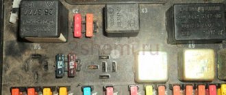
Fuse box VAZ-2110, VAZ-2111, VAZ-2112
VAZ-2110 fuses (number, rating and what they are responsible for)
Structurally, fuses are not provided only for the supply of current by the wire from the battery, in the car starting and ignition circuit, as well as for the wire going to the generator.
To replace a faulty fuse, first find the one that has blown and be sure to eliminate the cause. After that, install a new one of the same value.
Do not replace fuses with jumpers; this may cause blocks and devices to become unusable, as well as a wiring fire!
F1 - 5A - License plate lamps. Instrument lighting lamps. Side light indicator lamp. Trunk light. Left side marker lamps. F2 - 7.5A - Left headlight (low beam). F3 - 10A - Left headlight (high beam). F4 - 10A - Right fog lamp. F5 - 30A - Electric door window motors. F6 - 15A - Portable lamp. F7 - 20A - Electric motor of the engine cooling system fan. Sound signal. F8 - 20A - Rear window heating element. Relay (contacts) for turning on the heated rear window. F9 - 20A - Recirculation valve. Windshield and headlight cleaners and washers. Relay (coil) for turning on the heated rear window. F10 - 20A - Reserve. F11 - 5A - Starboard side marker lamps. F12 - 7.5A - Right headlight (low beam). F13 - 10A - Right headlight (high beam). Indicator lamp for turning on the high beam. F14 - 10A - Left fog lamp. F15 - 20A - Electric seat heating. Locking the trunk lock. F16 - 10A - Relay-breaker for direction indicators and hazard warning lights (in emergency mode). Hazard warning lamp. F17 - 7.5A - Interior lighting lamp. Individual backlight lamp. Ignition switch illumination lamp. Brake light bulbs. Clock (trip computer). F18 - 25A - Glove box lighting lamp. Heater controller. Cigarette lighter. F19 - 10A - Door locking. Relay for monitoring the health of brake light lamps and side lights. Direction indicators with warning lamps. Reversing lamps. Generator excitation winding. On-board control system display unit. Instrument cluster. Clock (or trip computer). F20 - 7.5A - Rear fog lamps.
Fuse box relay (number and what includes)
K1 – relay for monitoring the health of light bulbs; K2 – front wiper relay; K3 – repeater and alarm relay; K4 – low beam relay; K5 – high beam relay; K6 – additional relay; K7 – relay for turning on the heated rear window; K8 – backup relay (not installed on 110 series vehicles);
Electrical diagram of the VAZ-21102 car
| 1 — block headlight | 35 — instrument lighting switch |
| 2 - front brake pad wear sensors | 36 - ignition switch |
| 3 - reverse light switch | 37 - mounting block |
| 4 — electric motor of the engine cooling system fan | 38 - recirculation valve switch |
| 5 - sound signal | 39 — heater controller |
| 6 — gear motor for locking the right front door lock | 40 - hazard warning switch |
| 7 - power window relay | 41 — lamp illuminating the heater control levers |
| 8 - 8 A fuse | 42 — glove box lighting lamp |
| 9 - starter | 43 - glove compartment light switch |
| 10 - accumulator battery | 44 - cigarette lighter |
| 11 - generator | 45 — display unit of the on-board control system |
| 12 - windshield washer motor | 46 - ashtray lighting lamp |
| 13 — washer fluid level sensor | 47 — brake light switch |
| 14 — gear motor for locking the left front door lock | 48 — gear motor for locking the left rear door lock |
| 15 - left front door power window switch | 49 - left rear door power window switch |
| 16 — coolant level sensor | 50 — electric window motor of the left rear door |
| 17 - windshield wiper motor | 51 — socket for a portable lamp |
| 18 - recirculation valve | 52 - watch |
| 19 — micromotor gearbox for heater damper drive | 53 — electric window motor gearbox of the right rear door |
| 20 — electric heater motor | 54 — right rear door power window switch |
| 21 — trunk lock switch | 55 — gear motor for locking the right rear door lock |
| 22 - right front door power window switch | 56 - side turn signal |
| 23 — electric window motor reducer of the right front door | 57 - parking brake warning lamp switch |
| 24 — control unit for the door lock system | 58 — driver's seat belt sensor |
| 25 — additional resistor for the heater motor | 59 - directional lamp |
| 26 — brake fluid level sensor | 60 - interior lamp |
| 27 — electric window motor reducer of the left front door | 61 — cabin air temperature sensor |
| 28 - outdoor lighting switch | 62 — switch in the front door pillar |
| 29 — instrument cluster | 63 — switch in the rear door pillar |
| 30 - rear fog light switch | 64 — external rear light |
| 31 — fog light indicator lamp | 65 - internal rear light |
| 32 — indicator lamp for heated rear window | 66 — license plate lights |
| 33 — rear window heating switch | 67 - trunk light |
| 34 - Understeering's shifter |
A
— blocks for connecting the rear window washer motor.
B
- blocks for connecting the injection system harness.
C
- to the warning light harness block.
D
— block for connection to the on-board computer.
E
- to the headlight cleaner harness block.
F
— block for connection to the fuel level sensor in the electric fuel pump module.
G
- to the rear window heating element.
H
- block for connecting an additional brake signal.
J
- to the trunk lock motor.
The diagram does not conventionally show that in the instrument panel wiring harness, the second ends of all wires of white, black, orange, white with a red stripe and yellow with a blue stripe are connected to each other at the same points.
All mounting points weight VAZ tenth family
| If the electrics in the car start to malfunction, then one of the reasons for this ailment may be poor fastening of the battery mass. Ten have features of mass fastenings depending on the engine and year of manufacture of the car. We check all the attachment points of the negative wire: |
Location of masses in the car interior
| 1 - fuse block.2 - near the driver’s right foot there is a shield, which is attached with a couple of screws, removing it, you will see that everything is like in the picture.3 - in principle, the situation is similar to the point described above, except that the shield is located next to with the left leg of the navigator. |
| The stud in the dashboard behind the mounting block, in order to find it, you need to bend in a certain way. The headlight hydraulic corrector is shown there for reference; the ground pin is located above and to the left of it. Through this mass, the windshield wipers, heater fan (21124) and door lock activators are powered. |
| The console is on the right side, from here it is more convenient to check the very important ground pin, through which the bracket under the ECU is connected to the car body, and accordingly the reliability of the ground of the ECM and the cooling fan depends - this nut also holds the corner that supports the far part of the left panel of the console. |
| ECM harness mass crimps in the console. The connector was removed from the ECU and pulled out onto the driver’s mat, it’s more convenient. I bit the fan ground wire out of the ignition circuit crimp (left in the photo), extended it, put the tip on and connected it separately to the bracket. I soldered all connections for reliability. |
| Weight of the Electric Fuel Pump (EFP) module and fuel level indicator. A black and white wire is attached to the left rear handbrake lever mounting bolt under the floor tunnel. The fuel pump is powered through this mass, and the accuracy of the fuel level reading also depends on it. |
| The ground is on the stud of the fuel pump flange; this wire most likely connects the pump housing to the fuel filter bracket and this was done for safety reasons to equalize the potentials of these two devices. |
Location of masses under the hood of a car
| The thin wire connecting the minus battery and the car body is the main connection for all electricity consumers in the car, and in carburetor modifications also for the engine. Through this connection, all the car's lighting equipment, radio and other devices are powered, depending on the year of manufacture of the car. |
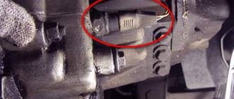
| The connection point for the negative terminal of the battery to the engine block is connected to the upper stud of the thermostat, if you look behind the air filter. The cross-section of the wire was chosen based on the large current consumption of the starter; this wire can easily be traced by hand if it is led from the battery. The starter current flows through this wire, charging the battery, some sensors screwed into the engine block are connected through it |
| Nearby there is another ground connection point to the engine block, it is slightly higher and to the left. The 2112 engine has two brown wires connected to this place - this is the mass of the ECM, that is, the mass of the sensors, ignition module, ECU and cooling fan. The arrow below shows the engine (starter) ground wire from the battery. |
| The mass point under the adsorber - Miha suggested that this is the mass of the right headlight and the mass of the right fog lamp. |
xn--2111-43da1a8c.xn--p1ai