The VAZ-1111 and 11113 Oka are equipped with all the necessary electrical equipment necessary to ensure traffic safety and create minimally comfortable conditions for the driver and passengers. All electrical appliances installed on a small car are connected by a single electrical network.
The on-board network used on Oka is 12-volt, DC, single-wire. The role of the second wire is performed by the car body and a number of components and mechanisms - the power plant, gearbox.
General scheme
The general diagram of the electrical equipment of the VAZ 11113 is presented below:
1 – turn signal repeater; 2 – front turn signal; 3 – headlight; 4 – el. fan motor with cooling; 5 – signal; 6 – fan switching sensor; 7 – el. washer pump motor; 8 – spark supply moment sensor; 9 – battery; 10 – starter; 11 – switch; 12 – candles; 13 – coil; 14 – generator; 15 – temperature sensor; 16 – oil pressure sensor; 17 – 12 V socket; 18 – windshield wiper relay; 19 – brake fluid level sensor; 20 – brake light switch; 21 – el. windshield wiper motor; 22 – el. carburetor magnetic valve; 23 – reverse light switch; 24 – starter relay; 25 – low beam relay; 26 – high beam relay; 27 – alarm relay; 28 – cigarette lighter; 29 – electric switch. stove motor; 30 – extra electric resistor stove motor; 31 — lighting switch; 32 – safety block; 33 — PTF power supply fuse; 34 – relay for turning on the rear window heater; 35 – electric switching relay. fan motor with cooling; 36 – parking brake control relay; 37 – rear window heater and washer switch; 38 – rear window heater switch; 39 – rear PTF switch; 40 – carburetor suction control; 41 – alarm switch; 42 – ignition switch; 43 – ignition relay; 44 – el. stove motor; 45 – fuel sensor; 46 – lamp switch; 47 – dashboard; 48 – windshield wiper switch; 49 – glass washer pump switch; 50 – signal switch; 51 – light switch; 52 – turn signal switch; 53 – brake light switch; 54 – interior lamp; 55 – carburetor suction control switch; 56 – el. rear window washer motor.
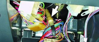
For ease of maintenance and troubleshooting, the wiring connecting the components of electrical equipment is color coded. Connecting devices to wires is carried out in different ways - through blocks, clamping with nuts, using sockets (light bulbs). In all cases, disconnecting the wiring is easy and does not particularly complicate the dismantling of electrical appliances during maintenance.
An electrical circuit combines all components related to electrical equipment. All components can be divided among themselves according to two criteria:
Peculiarity. An electrical circuit is the interweaving of certain sections of power circuits, especially the fuse box. That is, one fuse may be responsible for the operation of electrical appliances that do not interact with each other in any way.
Turn relay: the basis of car light signaling
All vehicles must be equipped with intermittent turn signal lights. Correct operation of turn signals is ensured by special relay-interrupters - read all about these devices, their types, design and operation, as well as selection and replacement in this article.
What is a turn relay?
Turn relay (turn signal breaker relay, current breaker) is an electrical or electronic device designed to close and open the circuit of a vehicle's light direction indicators in order to generate an intermittent signal to warn that the vehicle is performing certain maneuvers.
This device has four main functions:
- Formation of an intermittent signal from the direction indicator lights on one side of the car (on the right or left) when performing the corresponding maneuvers;
- Formation of an intermittent signal of all direction indicator lights when the hazard warning lights are turned on;
- Formation of an intermittent signal from the corresponding warning lamp on the dashboard;
- Generating an intermittent sound signal informing the driver that the direction indicators are on.
The breaker relay is part of three electrical circuits: two turn signal light circuits on the right and left sides of the vehicle, and one hazard warning circuit (which includes turn signal lights on both sides of the vehicle). To turn on the light alarm, the relay is connected to the corresponding circuit using the steering column switch. Therefore, usually only one turn relay is installed on vehicles.
Current traffic rules and standards establish that all motor vehicles operating on the territory of the Russian Federation must be equipped with direction indicators, and the use of this signaling is mandatory when performing any maneuvers. If the light alarm is not working, it is necessary to take measures to eliminate the malfunction; most often, repairs come down to simply replacing the turn signal breaker relay. But before you buy and change a relay, you need to understand the types of these devices that exist today, their design and characteristics.
Classification, design and principle of operation of the turn relay
Two main types of relays are used on cars, tractors and other equipment:
- Electromagnetic thermal;
- Electronic.
Design of electromagnetic thermal relay
Devices of these types differ in the physical operating principles embedded in them and, accordingly, in their design.
Electromagnetic thermal current interrupters. These are turn relays of an old design, which have been used on cars for several decades, but thanks to their simple design and reliability, they have not yet lost their relevance.
The basis of this device is an electromagnetic core with a coil and two steel armatures with contact groups. One armature is pulled away from its contact by a thin string of nichrome (a metal with high resistivity and a high coefficient of thermal expansion), the second armature is held at some distance from its contact by a springy bronze plate. The operation of this type of relay is quite simple.
When the turn indicators are turned on, current flows through the core winding, nichrome string and resistor, the resistance of this circuit is high, so the lamps glow at full intensity. Within a short time, the string heats up and, due to thermal expansion, lengthens - the armature is attracted to its contact and closes the circuit - in this case, the current flows bypassing the string and the resistor, the turn signal lamps glow at full intensity.
The de-energized string quickly cools, shortens and pulls the armature away from the contact - the circuit breaks, the current flows along the string again and the process repeats.
At the moment the contacts close, a large current flows through the electromagnetic core, a magnetic field is formed around it, which attracts the second armature - the second group of contacts is closed, which turns on the lamp on the dashboard. Thanks to this, the operation of the direction indicators is duplicated by the intermittent operation of the lamp on the dashboard. The described processes can occur with a frequency of 60-120 times per minute (that is, each cycle of heating and cooling of the string takes from 0.5 to 1 second).
Electromagnetic-thermal type relays are usually housed in a cylindrical metal housing with screw or blade contacts and can be mounted in the engine compartment or under the dashboard.
Electronic turn switches. These are modern devices that are used on all new cars. Today there are two types of electronic relays:
• With an electromagnetic relay for connecting the load (turn indicator lamps); • With an electronic key for connecting the load.
In the first case, the turn relay consists of two functional blocks - a simple electromagnetic relay and an electronic key on a semiconductor device (transistor or microcircuit). The electronic key acts as a clock generator, which, at a preset frequency, supplies current to the winding of the electromagnetic relay, and the relay contacts, by closing and opening, ensure that the direction indicators are turned on and off.
In the second case, instead of an electromagnetic relay, an electronic key with a powerful transistor is used, which ensures the connection and disconnection of the direction indicators with the required frequency.
Separation by purpose
By purpose, the equipment is divided into:
- Power supplies;
- Protective means;
- Controls;
- Instrumentation;
- Actuators;
Some circuit components have dual purposes. These include relays, which are both control elements and protective devices.
Power supplies
Power sources include the battery and generator. The battery powers the electricity. devices and ensures their operation when the power unit is turned off. After starting the engine, the on-board network is powered from the generator, which also ensures that the battery is recharged.
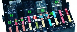
Protective components
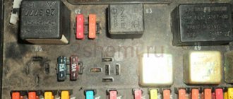
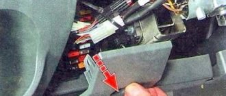
Protective means prevent burnout of electrical appliances and electrical circuits during short circuits. The main protective elements are fuses. For convenience, all protective elements are collected in one place - the fuse box, which in Oka is located under the front panel on the driver’s side.
Controls
Control elements include all components responsible for turning on, switching and turning off electrical appliances. This category combines the ignition switch, all kinds of switches and switches. Most of these elements are located within direct reach of the driver - on the front panel, steering column. But there are switches that the driver acts on through certain components - brake light switches, a sensor for turning on the choke warning light, etc.
Control and measuring devices provide the driver with information about the operation of certain components and mechanisms, operational indicators - fuel level, coolant temperature, oil pressure, etc. Some types of these devices display accurate information, while others are presented in the form of warning lamps that are triggered only when an emergency occurs. malfunctions.
Measuring instruments combine sensors installed on the required components and mechanisms, and signal elements located on the dashboard.
Actuating devices
Actuators are components that perform one or another function - they illuminate, operate components, etc. These include electric motors, lighting lamps, a sound signal, a cigarette lighter, etc.
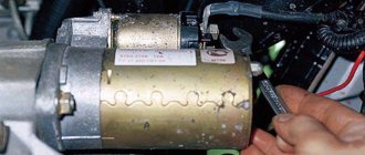
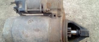
Main malfunctions and why the starter does not turn?
Malfunctions of the Oka starter, as well as the power electric motors of cars, are divided into two categories - mechanical and electrical. The first includes:
The most common mechanical failure is wear of the support bushings, which subsequently becomes the cause of other breakdowns. Due to significant wear of the bushings, the position of the armature and, accordingly, the bendix are disrupted. As a result, it is more difficult for the gear to engage, the wear rate of the teeth increases, and they may crumble.
Electrical faults include:
To this category of breakdowns you can also add problems with the power circuits of the electric motor and relay.
Malfunctions of the Oka starter manifest themselves in different ways:
If such signs occur, the unit should be repaired.
Division by function
As for functions, all electrical equipment is divided into systems that perform specific tasks:
- Take part in the operation of the engine;
- Ensure traffic safety;
- Create comfortable conditions;
There are also systems that are aimed at maintaining the functionality of the electrical circuit itself.
Systems responsible for engine operation
The ignition system takes part in the operation of the power unit and its task is to generate a spark in the engine cylinders to ignite the air-fuel mixture. The components of this system are a switch, a spark torque sensor, a coil and spark plugs. The system is turned on using the ignition switch. All of these components are connected by one circuit, the diagram of which is shown below:
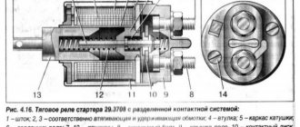
The second system related to electrical equipment and working with the engine is the starting system. To start the engine, a power electric motor is used - a starter, controlled from the same ignition switch. Its scheme is as follows:
Maintenance, repair
Of all the car’s electrical appliances, only power supplies require maintenance:
- Battery (periodic recharging using chargers, monitoring the level and density of the electrolyte);
- Generator (periodic check of drive tension, replacement of worn graphite brushes).
It is also important to monitor the condition of the wire insulation and prevent it from being damaged to avoid a short circuit. Oxidation of contacts often occurs at the wiring junctions, which can lead to failure of electrical appliances.
Most of the electrical network components are maintenance-free and must be replaced if they fail. Such elements include light bulbs, small electric motors, switches, relays, fuses, and sensors.
In the starter, generator, electric. In the heater and cooling system fan motors, mechanical breakdowns may occur - wear of bearings, bushings, brushes. All these components are repairable and it is often possible to restore their functionality by disassembling, troubleshooting and installing new parts to replace worn ones.
Replacement and size of bushings
Those car enthusiasts who have no desire to redo anything to eliminate armature play will have to change the bushings.
There will be no problems with the interior, since it is installed in the back cover and it is not difficult to get it out after removing and disassembling the starter. But the bushing, which is installed in a recess in the block, is difficult to get.
There are several options for extracting it:
If everything is clear with the first two methods, then the third should be considered in more detail. The method is based on the property of a liquid not to compress.
The extrusion technology is quite interesting - we select a rod whose diameter exactly matches the hole in the sleeve. Next, fill the bushing completely with grease (for example, “Solidol”). Then we insert the rod into the hole and hammer it inside. Due to compression, Solidol will penetrate under the bushing and begin to squeeze it out.
After removing the worn bushing, we install it in its place with a new one, after which all that remains is to put the starter in place.
Fuse box diagnostics (video)
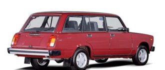
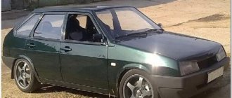
We present to your attention the electrical circuits of equipment for the VAZ-1111, also known as OKA, 1988-2003. 4-seater hatchback of a particularly small class with a transverse engine and front-wheel drive. Production of the Oka began in 1989 at the Volzhsky Automobile Plant. The engine is a two-cylinder with a displacement of 650 cc, in 1997 it was increased to 750 cc. volume. Currently, the production of Oka cars has been transferred to the Kama Automobile Plant, as well as the Serpukhov Automobile Plant. In addition to the basic models KamAZ-11113 and SeAZ-11113, manual control options are available for disabled people. Due to its very low price, it is of interest for export. This small car was developed at the Volzhsky Automobile Production Plant at three factories - VAZ, KamAZ and SeAZ - in a disabled version, and has been produced since 1990.
Electrical diagram for OKA
1 - side turn signal repeater 31 - exterior lighting switch 2 - front turn signal 32 - fuse block 3 - headlight 33 - fog light circuit fuse 4 - cooling fan motor 34 - rear window heating relay 5 - horn 35 - power relay cooling system fan electric motor 6 – fan electric motor activation sensor 36 – parking brake warning lamp relay-breaker 7 – windshield washer motor 37 – rear window wiper and washer switch 8 – spark torque sensor 38 – rear window heating switch 9 – battery 39 - rear fog lamp switch 10 - starter 40 - carburetor choke control lamp 11 - switch 41 - hazard warning switch 12 - spark plugs 42 - ignition switch 13 - ignition coil 43 - ignition relay 14 - generator 44 - heater fan motor 15 - coolant temperature gauge sensor 45 - fuel level gauge sensor 16 - low oil pressure warning lamp sensor 46 - courtesy light switch in the door pillar 17 - socket for a portable lamp 47 - instrument cluster 18 - windshield wiper relay 48 - windshield wiper switch 19 - level sensor brake fluid 49 – windshield washer switch 20 – brake signal switch 50 – horn switch 21 – windshield wiper motor 51 – headlight switch 22 – carburetor solenoid valve 52 – turn signal switch 23 – reverse light switch 53 – warning lamp switch parking brake activation 24 – starter activation relay 54 – interior lamp 25 – headlight low beam relay 55 – carburetor choke control lamp switch 26 – headlight high beam relay 56 – rear door glass washer motor 27 – alarm breaker relay and direction indicators 57 - rear light 28 - cigarette lighter 58 - rear fog light 29 - heater fan switch 59 - license plate light 30 - additional heater motor resistor 60 - rear door glass heating element 61 - rear door glass wiper motor A - numbering order contacts in connecting blocks
The principle of operation of turn signals
Turn signals (direction indicators) are an essential part of the lighting equipment of any vehicle. On each vehicle they must be installed on both sides, front and rear (on trailers - only the rear) and are orange lights (in some countries red is allowed). Before starting the maneuver (the exact distance or time is not regulated by traffic regulations), the driver must turn on these lights on the side in which the turn will be made (in addition to the function of indicating a change in direction of movement, the turning lights provide an emergency signal).
The lamps should operate in flashing mode. This requirement is related to the peculiarities of human perception - we better notice not the intensity (brightness) of the signal, but its change. Therefore, a flashing flashlight quickly attracts attention, even if it is visible in peripheral vision. In addition, it is more difficult to confuse it with marker lights or other lighting equipment. Intermittent lighting in the most modern cars is provided using electronic units that include other operating functions. In machines developed in previous years (and they are the majority), the blinking function is provided by relay interrupters.
How should a relay work correctly?
The main requirement for the breaker relay is to generate an intermittent electrical signal with a frequency of 30-12 Hz to supply the turn signal lamps. Additional features are also desirable:
- control of the warning lamp on the instrument panel;
- monitoring the serviceability of lamp filaments;
- generation of a sound signal for audio monitoring of the turned on state of the turn signals.
In breakers built on electromagnetic relays, the sound is produced by itself - characteristic clicks occur during operation. In relays made on solid-state switches, additional elements are provided for this function.
Electrical diagram of VAZ-1111 and VAZ-11113 cars
Oka cars use a single-wire circuit for connecting electrical equipment, i.e., only one wire is suitable for all electricity consumers. The second “wire” connecting consumers to sources of electricity is the car body, or “ground”. This scheme allows you to significantly reduce the number of wires and simplify their installation. The negative terminals of the electricity sources are connected to ground. With this connection, the corrosion of metal body parts due to electrochemical corrosion is reduced.
The sources of electricity in a car are a generator and a battery connected in parallel. The rated operating voltage of electricity sources and consumers is 12 V. However, the voltage in the electrical equipment system, depending on specific conditions, can range from 11 to 14.5 V, and within these limits, consumers remain operational.
Repair of starter retractor relay VAZ Lada Oka 1111 in auto repair shops in Moscow
18 car repair companies
- TTS Motors
- Pyatnitskoe highway, 2
- +7 (495) 24… show all
- The site of the company
- Lorant
- Atlant-m
- Motorway
- Lexus on the market
- Auto-rad
- Technical center gm east
- Auto complex
- Ddcar
- Nivus
- Bers-auto
- Master motors
Popular companies