Greetings, friends! About a month ago, two weeks before my vacation, I decided to clean my air conditioner using a foam cleaner. I did everything according to the instructions, after which I got behind the wheel and discovered that the heater fan did not turn off, worked at half power in the “off” position, and responded adequately to an increase in power. First of all, I decided to check the control transistor (aka resistor, aka rheostat) located in a very good place - and I was right, it was all covered in liquid.
After cleaning everything with a degreaser and drying it thoroughly, I install it back - and, voila, everything works!
A week and a half passes, I, having packed to capacity, leave on Friday at 19.00 in the direction of the Crimea and discover that the stove fan is not spinning. I remove the transistor again - I immediately smell the specific smell of burnt PCB, and immediately start calling all the stores operating in my city. Naturally, the result is practically zero - out of stock, they will deliver it on Monday, which is categorically not satisfactory. I start looking around the showrooms in St. Petersburg, I find it in Euroauto (not advertising! and you will soon understand why!), they are open until 21.00, at 20 o’clock. I call a friend, outline the situation, transfer him 2 tr. for transistor + 1 tr. for your concern and I'm waiting. He rushes to the store, picks up the pre-booked part, takes it to the Peter-Pskov minibus and hands me the spare parts with the driver. At 6.00 I pick up the spare part, install it in place, and... and it doesn’t work. I go home, pick up a soldering iron, disassemble the original rheostat, and discover a cracked field-effect transistor. Having read the markings on the body of the field worker, I rush to the only radio parts store open at 9.00, where the girl tells me that they don’t even have anything similar. I’m driving home, I smoke online, I pick up a field pot with a similar value but a different size, I’m already on my way to the store closest to me, it’s 10.00. Luckily for me, I find it in stock and take three at once. It’s worth noting here that they really differ significantly in size - the analogue is much smaller, its legs are shorter, they have to be bent, and because of this there is no way to screw it to the radiator. Having started soldering, I find a blown thermal fuse, put a jumper, solder in an analog transistor, don’t put it on the radiator, go check it - everything works, hurray! So you need to come up with something and do it right. I'm on my way to get thermal fuses, the clock says 12.00. The salesperson in store No. 1 has changed, I decide to ask him about the transistor, and what do you think?! There is, just “the same one, only on a different collective farm” I drove 6 thousand km, with the air conditioning almost always on, so the spare parts I bought were never useful.
Upon arrival home, without haste, it was decided to restore the rheostat to its nominal value, so I’ll tell you how to do it.
An electrical circuit is impossible without the presence of resistance in it, which is confirmed by Ohm's law. That is why the resistor is rightfully considered the most common radio component. This state of affairs suggests that knowledge of testing such elements can always be useful when repairing electrical equipment. Let's consider the key issues related to how to check a regular resistor for serviceability using a tester or multimeter.
Main stages of testing
Despite the variety of resistors, conventional elements of this class have a linear current-voltage characteristic, which greatly simplifies the test, reducing it to three stages:
- visual inspection;
- the radio component is tested for breakage;
- Compliance with the nominal value is checked.
If everything is clear with the first and second points, then with the last there are nuances, namely, you need to find out the nominal resistance. Having a schematic diagram, this will not be difficult to do, but the trouble is that modern household appliances are rarely equipped with technical documentation. You can get out of this situation by determining the denomination from the markings. We'll briefly tell you how to do this.
Replacing the heater (heater) resistor — Lada Priora Sedan, 1.6 l., 2007 on DRIVE2
Good day)))
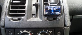
The first blog is about repairing the stove, namely replacing the heater resistor. I woke up one winter morning to go to work and decided to go by car. I started the car and went to wash myself. I checked the heating temperature of the car, the engine got hot, but the minus in the cabin remained the same. I think I forgot to turn on the stove. I went out early while I think I’ll sweep away the snow at the same time and the interior will warm up. But it’s not like the stove is in position 1, but it’s not blowing, I switched to position 2 with zero emotions, in position 3 it’s the same story, but in position 4 it blows well. Time is running out, I ran to the bus and decided to leave the problem for the evening. At work, the thought of a non-working stove would not leave me alone. At lunchtime I went online and searched the forums, everyone was unanimously talking about the heater resistor. They say the prior is sick. At the same time, the interior was replaced. This was the first time I encountered this, and at the end there were a couple of other photos about the repair))))) For any questions, please PM me)))
Pee...don’t throw tomatoes at me for the first time as I’m writing this)))))
Color designation
Now color marking has been adopted, representing from three to six rings of different colors (see Fig. 2). There is no need to see this as the machinations of enemies, since this method allows you to set the denomination even on a heavily damaged part. And this is a significant factor, given that modern household electrical appliances are not equipped with circuit diagrams.
Rice. 2. Example of color marking
Information on decoding this designation on components is easy to find on the Internet, so it makes no sense to present it within the framework of this article. There are also many calculator programs (including online) that allow you to obtain the necessary information.
Types of markings
On components produced during the Soviet Union, it was customary to indicate the denomination on the body of the part (see Fig. 1). This option did not require decoding, but if the integrity of the structure was damaged or the paint burned out, problems with text recognition could arise. In such cases, you could always turn to the circuit diagram that supplied all household appliances.
Figure 1. “ULI” resistor, the part rating and tolerance are visible on the body
Marking of SMD elements
Surface-mounted components (for example, SMD resistor, diode, capacitor, etc.) began to be marked with numbers, but due to the small size of the parts, this information needed to be encrypted. For resistances, in most cases, a designation of three numbers is accepted, where the first two are the value, and the last is the multiplier (see Fig. 3).
Rice. 3. An example of decoding the value of an SMD resistor
Resistor characteristics
Resistance values are standardized in series and cannot take any value. For them, permissible deviations from the nominal value are specified, depending on the manufacturing accuracy, ambient temperature and other factors. The cheaper the resistor, the greater the tolerance. If, during measurement, the resistance value goes beyond its limits, the element is considered faulty.
Another important parameter is the power of the resistor. One of the reasons for premature failure of a part is its incorrect selection according to this parameter. Power is measured in watts. It is chosen the one for which it is designed. In the symbol diagram, the power of the resistor is determined by the signs:
- 0.125 W - double slash;
- 0.5 W - straight longitudinal line;
- Roman numeral - power value, W.
The replacement resistor is selected according to the same parameters as the faulty one.
Visual inspection
Violation of the normal operating mode causes overheating of the part, therefore, in most cases, the problematic element can be identified by its appearance. This can be either a change in the color of the case or its complete or partial destruction. In such cases, it is necessary to replace the burnt element.
Figure 4. A clear example of how a resistor can burn out
Pay attention to the photo above, the component clearly needs to be replaced, while the neighboring parts “2” and “3” may be working, but they need to be checked.
Operating principle
The operating principle of all rheostats is similar. The slider rheostat has the simplest design and visually clear principle of operation. It is connected to the circuit through the lower and upper terminals. The design is made in such a way that the current does not pass across the turns, but through the entire length of the wire selected by the slider. This occurs due to reliable insulation between the conductors.
Slider positions
In most slider positions, only part of the rheostat is activated. In this case, changing the length of the conductor leads to regulation of the current strength in the circuit. To reduce wear on the turns, the slider has a sliding contact, often made of a graphite rod or wheel.
Slider rheostat device
This is interesting: Technical characteristics of 4A GE 1.6 l / 115 - 240 l. With.
The rheostat has the ability to operate in potentiometer mode. To do this, when making a connection, you must use all three terminals. The bottom two are used as an entrance. They are connected to a voltage source. The top and one of the bottom terminals are output. When you move the slider, the voltage between them is adjusted.
Rheostat used as a voltage divider
In addition to the potentiometer, a ballast mode of operation of the rheostat is also possible, when it is necessary to create an active load for energy consumption. In this case, it is necessary to take into account what scattering abilities the device has. Excessive heat can damage the device, so it is recommended to connect the rheostat to the network, having previously calculated the power dissipation and, if necessary, ensure sufficient cooling.
Checking for a break
Actions are performed in the following order:
- We turn on the device in the “dialing” mode. In Figure 5 this position is marked as “1”.
Rice. 5. Setting the mode (1) and connecting probes (2 and 3) - We connect the probes to sockets “2” and “3” (see Fig. 5). Despite the fact that in our testing polarity does not matter, it is better to immediately train yourself to connect the probes correctly. Therefore, we connect the red wire (+) to socket “2”, and the black wire (-) to “3”.
If the model of the device you are using differs from the one shown in the figure, read the instructions that came with the multimeter.
- We touch the pins of the problematic element on the board with the probes. If the part “does not ring” (the multimeter will show the number 1, that is, an infinitely large resistance), we can state that the test showed a break in the resistor.
Please note that this testing can be carried out without desoldering the element from the board, but this does not guarantee a 100% result, since the tester can show communication through other components of the circuit.
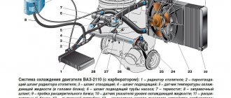
Cooling system
So, the load resistor is used in the car’s cooling system, or more precisely, in the radiator fan power circuit.
It is worth noting that previously this electrical element was not used in this circuit, and everything worked very simply - when a certain coolant temperature was reached, the temperature sensor closed the contacts of the fan power circuit, and it started working.
The use of a resistor made it possible to make the fan motor operate in two or even three modes.
The process of supplying power to the fan has changed somewhat. Relays have also been added to the system, and in modern cars the electronic control unit is already responsible for turning on the fan.
That is, the electronic unit analyzes the temperature readings of the sensor and sends a signal to the relay.
Depending on the temperature, the relay directs electricity through a specific circuit. If the coolant temperature is slightly exceeded, but it is already required to be reduced, and a signal from the ECU is received, the relay directs electricity through a load resistor, which creates resistance, and the fan begins to rotate at low speed.
Validation check
If the part is soldered, then this stage will guarantee its functionality. For testing we need to know the denomination. How to identify it by markings was written above.
The algorithm of our actions is as follows:
- We connect the probes as in the previous testing.
- We turn on the resistance measurement (the range is shown in Figure 6) in a mode greater than the nominal value, but as close as possible to it. For example, we need to test a 47 kOhm resistor, therefore, we need to select the “200K” range.
Figure 6. Resistance measurement ranges (marked in red) - We touch the terminals with the probes, take readings and compare them with the nominal value. If they do not match, and this can be guaranteed with a probability close to 100%, do not despair. Both the error of the device and the tolerance of the element itself should be taken into account. A little clarification is necessary here.
Purpose of rheostats
According to their purpose, rheostats are divided into the following types:
- starting ones, used to reduce the starting current when starting the electric motor;
- ballasts, used primarily in DC motors, as well as with alternating voltage in the case of an asynchronous electric motor with a wound rotor;
- load, creating resistance in the electrical circuit;
- ballast, necessary to absorb excess energy that occurs, for example, when braking an electric motor.
Rheostats are also used to limit the current in the excitation winding of DC electrical machines. Thanks to this, it is possible to achieve a reduction in electrical current surges and dynamic overloads that can damage both the drive itself and the mechanism connected to it. The use of resistance at start-up extends the life of the brushes and commutator.
A special type of rheostat is a potentiometer. This is a voltage divider based on a variable resistor. Thanks to it, electronic circuits can use different voltages without using additional transformers or power supplies. Adjusting the current strength using a rheostat is widely used in radio engineering, for example, to change the volume of a speaker.
What is clearance and how important is it?
This value shows the possible deviation of a given series from the specified nominal value. A correctly calculated circuit must take this indicator into account, or appropriate adjustments are made after assembly. As you understand, our friends from the Celestial Empire do not bother themselves with this, which has a positive effect on the cost of their goods.
The result of such a policy was shown in Figure 4; the part works for some time until the limit of its safety margin is reached.
- We make a decision by comparing the readings of the multimeter with the nominal value; if the discrepancy goes beyond the error limits, the part definitely needs to be replaced.
How to check a resistor without desoldering: visual check
The process of checking a resistor for functionality directly on the board without completely desoldering is a rather labor-intensive task, so you can first determine the burnt part visually. First of all, inspect the case for damage and chips, and the reliability of fastening the terminals. Malfunctions are indicated by:
- Darkening of the body. A burnt resistor has a darkened surface - completely or partially in the form of rings. Slight darkening does not indicate a malfunction, but only overheating, which did not lead to complete failure of the part.
- The appearance of a characteristic odor.
- Erasing markings.
- Presence of burnt tracks on the board
If conditions allow, the faulty resistor is soldered off, and a new one with the same rating is soldered in its place.
Inspection does not guarantee an accurate determination of serviceability; the resistor may look like new even with a broken contact.
How to test a variable resistor?
The principle of operation in this case is not very different; we will describe them using the example of the part shown in Figure 7.
Rice. 7. Trimmer resistor (internal circuit marked with red circle)
The algorithm is as follows:
- We take a measurement between legs “1” and “3” (see Fig. 7) and compare the resulting value with the nominal value.
- We connect the probes to terminals “2” and any of the remaining ones (“1” or “3”, it doesn’t matter).
- We rotate the adjustment knob and observe the readings of the device; they should change in the range from 0 to the value obtained in step 1.
Toyota Corona › Logbook › Resistor and power transistor for the heater fan.
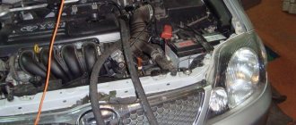
A few days ago, after turning on the heater fan, I found out that the fan only works at max. rpm I've seen problems like this on other cars before. I opened the diagram and saw that at max. voltage is applied bypassing the resistor and transistor. It means it’s in them, I found in catalogs where these things are schematically located. Above the cabin filter window are both elements.
I unscrewed the resistor and the thermal protection triggered. no question - soldered
I put it in place and the first speed appeared)) on the first, second and third button, on the fourth max... I remove the transistor, disassemble it...
Transistor 2SD1460 TOSHIBA and thermal fuse 2A and temp. actuation 114 gr.ts.
I call the fuse and there is no continuity. I go to the radio parts store, buy 2 fuses (slightly different type and operating temperature 115), find out the price of the transistor and if it even exists... yes, 104 rubles. I take it just in case, and crimp it
th: 104+25+25+8+8+6+6=182 rub. I am assembling an old transistor with axil thermal paste, for better heat dissipation, the main thing is to prevent the paste from getting on the legs of the transistor when squeezing, so as not to short-circuit
I check, everything works, but the speed seems a little low, I take it apart, put it back together with a new one, it’s better,
much better))) New transistor (assembled) 88750-20020, costs from 1500 rubles, saved 1318 rubles. There are a couple of buts left: 1. the resistor gets very hot, of course it should get hot, but there’s something I don’t like, it’s non-separable - ceramic, there should be nichrome springs under it... I didn’t bother picking, the price of a new one is 396.52 (87138-20230), The original is from the Emirates, will arrive on June 14. 2. why both thermal protections were turned off... the impeller of the stove fan is clean (I have a dust pre-filter), i.e. it couldn’t stall, maybe it’s the resistor... I don’t like it when the root cause is not found(
What tools should be used for diagnosis?
You can check the power supply to the engine connector with a regular test. But when carrying out full diagnostics and identifying faults of a high degree of complexity, a multimeter is needed. If you have knowledge of using a multimeter, you can easily measure the power on the connectors and check the resistance, which will make it possible to quickly troubleshoot wiring problems or identify problems with resistors.
In addition, measuring resistance and diagnosing wires in this mode will greatly facilitate the search for a short circuit.
You can diagnose PWM controllers for electrical systems that control fan speed using an oscilloscope. But purchasing this device for diagnostics is not advisable due to its high cost.
Isn’t it better to use the diagnostic methods listed below, which in most cases will help identify the sources of malfunctions in the stove fan without expensive equipment. So let's get started.
If it is impossible to start the fan , this situation occurs due to:
- worn brushes. When performing the functions of a conventional DC motor for a stove fan, the main problem is the abrasion of the brushes, with the help of which voltage is supplied to the commutator. With strong abrasion of the copper-graphite brushes, the pressing spring force that creates the contact is reduced, which in turn leads to the fan operating at a variable frequency. For example, it turns on when you hit the front panel or hit potholes in the road.
- faulty electrical control circuits. The source of the problem is contacts that have been sealed off due to strong heating;
- break in wires, oxidized contact;
- blown fuse element. If a fuse constantly blows (after replacing it), the technician must find a section of the circuit with a short circuit.
Where is the stove rheostat located?
Theme Options
Replacing and checking the heater fan motor speed resistor (rheostat)
Replacement and revision of the heater fan motor speed rheostat resistor
(rheostat) stove fan speed. I climbed in to look and there was a collective farm there. There is a ceramic resistor, the ceramics have practically crumbled, a non-original connector is screwed on. In general, I bought a used resistor along with a connector and a stub of wires. I installed it - there is no first speed, so I decided to revise it. The audit does not take much time and does not present any difficulties.
This is the resistor (rheostat) I bought:
To check we use a regular multimeter. I check the first speed - a break. It is clear that the breaking resistor, which is located under the metal plate, is broken. I remove the plate, clean everything with alcohol, and solder the breakage area. By the way, you need to solder not with ordinary flux or rosin, but with soldering acid or, if it’s hard to find, then use an acetyl tablet (aspirin) as a flux. Solder is standard.
At the end of the work, I wipe everything with alcohol, clean the contacts with zero, and go to put it in place. There is no need to remove the glove compartment) I screwed it with ordinary long, construction self-tapping gnomes.
That's it, I turn on the ignition, everything is in good order - the stove blows in all positions
Last edited by ROW111; 02/06/2014 at 07:10.
Sometimes I like to read about equipment repairs, so I decided to share my experience. This time we are fixing a malfunction of the engine speed controller of a car heater. I am sure it will be useful to many, since the design of the breaking element is identical in the vast majority of cars, from VAZs to foreign cars.
Symptoms: the heater regulator does not work at speeds 1, 2, 3, but works at the highest - speed 4.
Diagnosis: the thermal fuse of the stove speed control resistor has burned out.
1. Replacement of the entire resistor. The price of a spare part is on average $7-15. Replacing it yourself takes 5-10 minutes.
2. Self-repair - replacing the thermal fuse. Spare part price $0.3-0.4 Self-replacement - 10-15 minutes. Do you feel the difference?
Repair procedure for example Ford Torneo Connect.
We open the glove compartment. To the left of the stove body there are two bundles of wires, one of which goes down to the connector in the air duct housing.
Disconnect the connector (from the resistor). The resistor itself is screwed into the air duct with one self-tapping screw. There it is blown with cold air, since it has a fairly high operating temperature.
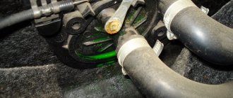
Unscrew the screw and remove the resistor (the green one). There is usually no visible damage on it.
With a tester, just in case, we ring the rheostat plates (those that are embedded in a green insulator). Then we call the thermal fuse located at the end. If it does not ring, it means it is burnt out and must be replaced.
We buy the same thermal fuse, or a little higher according to the temperature indicators indicated on its body. In my case, at 250V 10A with a temperature of 223 degrees (standard 216 degrees).
You can't solder - it will fall off. Either spot welding (you can ask for this service on the radio market), or connect the terminals of the resistor with the terminals of a thermal fuse by crimping them using short pieces of a thick-walled copper tube or using a screw clamp cut in half from an electrical divisible block with a hole of a suitable diameter (from the block, like on the picture).
We install the resistor in the car, connect it and enjoy the results of our work.
Sprinter W901-W905. Electrics. Club of fans of minibuses and minivans
- Unanswered topics
- Active topics
- SearchMobile version
Sprinter W901-W905. Electrics ⇒ Where is the heater fan rheostat for the 312 Sprinter?
Moderators: ka750, Edison
Post by SLy » Apr 09, 2012, 00:01
Post by Serg4180 » 09 Apr 2012, 10:28
Post by SLy » 09 Apr 2012, 14:12
Post by Serg4180 » 09 Apr 2012, 20:09
Self-diagnosis of stove malfunction
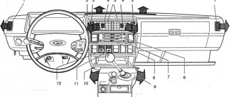
If the safety elements are intact, you need to check how efficient the fan is by first opening its power supply connector. The electric motor in the stove is located either in the space under the hood (behind the engine shield near the passenger compartment), or under the dashboard of the car interior.
The location of the heating fan and how to open it are in the vehicle operating instructions. There is also a circuit for starting the fan.
When studying the circuit, you need to find out which of the connector pins of the electric motor is positive when starting the first speed of the fan. Next, any contact of the control device is connected to this pin, another of its contacts is shorted to ground, the ignition system is turned on and the fan switch is turned to any position. If the control lamp turns on, then the cause of the fan malfunction is the electric motor. Otherwise, fan malfunctions occur due to a break in the wiring leading to the heating switch.
Heater fan not working
It is quite simple to understand that the car's heater fan is faulty. To do this, just start the car and switch the heater operating mode. If during the switching process no additional sounds appear in the vehicle interior, this means that the heating system fan is not working. At the same time, if the fan does not spin only at certain speeds, then the problem is not in the fan itself, but either in the resistor or in the heating intensity toggle switch.
The stove fan does not work - the main reasons
There are six main reasons why the stove fan may not work:
1. The fuse has blown.
This is the most banal and simple reason, but at the same time the most problematic. The thing is that replacing a fuse is a very simple procedure that anyone, even the least experienced car owner, can handle. But it’s very difficult to identify the short circuit that caused it to burn out. To do this, you will have to go through the entire electrical circuit of the car's interior heating system.
Video. The fan on the VAZ 2110 does not work
It is worth noting that the fuse marked F7, which has a current strength of 30 amperes, is responsible for the operation of the stove. Note that the same fuse is responsible for the glove compartment lighting, the cigarette lighter, the rear window heating system, as well as the electric headlight washer motor. This means that if you do not find the cause of the short circuit in the electrical circuit of the heater, you will have to go through almost the entire wiring of the vehicle.
2. Poor quality contact inside the mounting block.
Oxidation of the contacts inside the mounting block is a very common cause of stove fan malfunction. To make sure of this, you need to move the block on which the flagella are attached; if the fan starts working, then remove it and clean the contacts.
3. Flooding the relay of the vehicle ignition system.
This problem is diagnosed quite simply. If your heater starts working only after the car has “warmed up”, then the reason is in the ignition relay. The only way to fix this problem is to replace the relay. It is located under the dashboard.
The main reasons for the failure of the stove fan
There are many more reasons for failure, they arise for a variety of reasons, we will look at the most basic causes of failure, which even an ordinary car enthusiast who is not involved in professional repairs can eliminate.
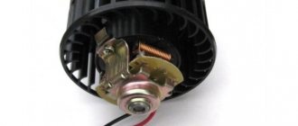
The stove brushes are worn out or damaged
In such a situation, you need to disassemble the stove motor and be sure to replace the brushes. To do this, the impeller wheel is removed from the electric motor housing (it is usually secured with latches). If the catalog of automobile spare parts does not contain the necessary brushes, then you can unsolder the old analogues and replace them with identical ones in size. As a last resort, graphite-copper brushes are filed using a needle file.
Naturally, soldering brushes cannot be done without solder, rosin and a soldering device. After replacing the brushes when assembling the electric motor, it is necessary to clean its insides from the wear product of the outdated brushes.
If squeaking or noisy sounds occur during operation of the fan, it is necessary to lubricate the bushings with a lithol solution when repairing it. To do this, a small portion of lubricant is placed on the bushing (its end) and then heated to ensure it flows inside. When the fan operates silently, lubrication of its bushings is excluded, since the lubricating solution, trapping dust, turns it into a viscous paste, making it difficult for the fans to operate .
The fan runs at maximum speed or does not switch.
If the fan only operates at maximum speed or it is impossible to switch to one of its speeds, this problem occurs due to damaged additional resistors used in the electrical circuits on most machines.
How to test a resistor?
Additional resistors are checked using a multimeter. The diagnostic process consists of measuring the resistance value of the terminals of this electrical element, as well as comparing the obtained values with the resistor values specified in the instructions for a particular machine. In this case, it is worth checking the condition of the thermal fuse, which can burn out if there is a short circuit. Sometimes a problem arises when the resistor is desoldered due to its high heat. A new resistor with identical parameters is selected on the radio market.
The automatic heating control system does not function.
The sources of the problem are the temperature sensor, the sensor that fixes the position of the air dampers, the control electrical circuit, as well as the automatic electronic control module unit. Using the above information, you can easily determine the cause of the stove fan failure, and if you have experience working with electricity, you can repair this element yourself.
Resistor ® is a passive element of electrical circuits that limits the voltage or current in a certain section of the circuit due to its resistance. Resistors are the most common parts in electrical and electronics. Many novice radio amateurs are wondering how to test a resistor with a multimeter. To determine the resistance value, digital and dial multimeters, or testers, are used.
About the stove fan, about the rheostat and self-repair. [ChinaWiki]
One morning, when starting the car, the heater fan blew out to full capacity and flatly refused to obey the control unit buttons. Turning off the ignition did not help either; the fan went out only when the terminals were disconnected from the battery. It looks like my stove was visited by a white fluffy animal. There is a lot of information on the forum, but it is scattered and poorly systematized. Well, I’ll take this opportunity to describe in detail the solution to the problem in relation to Gzhelts.
Let me start with the fact that there are many types of stove control units. The fan speed is adjusted through RHEOSTAT, which either contains a set of wire resistances (8104200-D01, 8107130-D07), or an electronic module with a field-effect transistor (switch) 8107200-F00. What is the difference can be seen in the photo at the link: https://www.chinamobil.ru/bb/files/_0001_773.jpg https://www.chinamobil.ru/bb/files/_0002_924.jpg The block with resistance wires must only be changed assembled - nichrome cannot be soldered with ordinary solder. The Gzhel is equipped with a power supply unit with electronic fan speed control; its full name, according to the diagram, sounds like AIR FLOW SPEED CONTROL MODULE. There is a connection diagram in the next VIKI thread. The PCB generates a signal that is supplied to this module and, depending on the voltage, the key transistor causes the stove motor to change its speed.
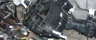
So, in order: Getting to the rheostat is not easy, it is hidden deep in the bowels of the torpedo, and this was done this way because the key transistor gets quite hot during operation, so they placed it closer to the fan impeller, sacrificing accessibility. In this case, the value of its permissible current decreases linearly when heated. So if you decide to move it, think twice!
We completely remove the glove box and see this:
We remove both controllers and preferably the fuse panel. Remove the fan housing with the recirculation curtain:
And here is the larger connector you are looking for:
Getting to the distant screw that secures the rheostat, of course, is still the same. I was helped out by the pieces of hardware at hand:
Many more photos from the forum
IMPORTANT NOTICE! Let’s agree in advance that the PCU is serviceable, how it was checked: by replacement or by testing is a separate topic. In my case, the screen glowed and the curtains changed their positions when the buttons were pressed. Only the fan was making noise all the time at maximum speed.
Make sure that the battery terminals are not loose or oxidized!!! A bad contact of the negative terminal can easily send another key transistor in the rheostat into the world. The rheostat itself is quite reliable. Almost the same one was installed on a bunch of foreign cars, so the Chinese were not original, but stupidly ripped off the finished module from a used sample.
On the left is 8107200-F00, on the right is its brother from NISSAN-MAZDA, the circuits are similar. By the way, on the Japanese it burns in exactly the same way and because of the same problems, so before repair I strongly recommend checking the condition of the connectors and the heater motor itself. The module starts to burn when the load current increases or there is a short circuit in the wires (connectors). The stove motor connector very often melts, which leads to a short circuit between the terminals. Before undertaking repairs, it is initially necessary to exclude these reasons .
We remove and disassemble the stove motor for inspection. The motor should not jam, the impeller should not catch on the housing, the brushes should be of normal length and move freely. The standard motor is made quite decently; there is even a balancing weight on the impeller. If the shaft is not crooked or jammed, the armature is not short-circuited, etc., then to be honest, I don’t understand the desire to buy something in return with an unguaranteed result. Worn brushes are no longer a reason; they are replaced with an analogue one.
But this should not happen:
It should be like this:
Pay attention to the connector of the stove - it gets very hot when operating at full load and has already begun to melt, it won’t be long before it shorts out. He was saved even earlier by a burnt-out key transistor.
We blow, clean and assemble the fan.
Now let's move on to the rheostat. From the connector side, the module board looks like this. The white crap on the transistor and radiator is KPT-8 thermal paste, it improves heat dissipation and is a must for use!
The arrows indicate the places where the thermal fuse is soldered; before disassembling, it is advisable to desolder the legs, otherwise there is a possibility of tearing them off. Its purpose is to protect the key transistor when the permissible current or temperature of the crystal is exceeded - when it burns out, it breaks the control circuit of the PCB and the transistor is locked. Although quite often its performance is not enough and the transistor manages to burn out. It is checked like a regular fuse and checked with an ohmmeter. It looks something like this:
An alternative can be an ordinary paperclip, but you must be aware that a bug in the protected circuit does not really add reliability to the node.
Module board from the side of the mounted elements:
Photos of connectors. It shows that the PLUS (gray with a blue stripe) is permanently connected to the stove motor through a 30A fuse and is not turned off by the ignition switch. Orange with a green stripe is power switching. The blue wire carries a control signal from the PCB. MINUS (black) is connected via a rheostat, or bypass via a relay (in the photo it is at the very bottom of the block). Absence or poor contact between the black wire and the ground of the car is not allowed!
The key transistor is closed in good condition, the relay is de-energized - the motor is motionless. When a signal is supplied from the PCU, the transistor opens slightly and causes an increase or decrease in engine speed. When the relay is turned on, battery voltage is supplied to both motor terminals, the speed is maximum. If the transistor is broken, then MINUS is constantly applied to the second terminal of the motor and the speed is not regulated.
ANOTHER IMPORTANT NOTE! For many types of field-effect transistors, the middle terminal is not isolated from the metal substrate; accordingly, voltage is also present on the rheostat radiator - therefore it should not come into contact with metal parts of the body. Field-effect transistors are very sensitive to static electricity, so it is better to solder them using a soldering station, or by tying the terminals with wire or foil - naturally, remove the wire after soldering. If there is poor contact with the battery terminals when starting the internal combustion engine, a pulse noise may occur in the on-board network. It can be very short-lived (a needle on the oscilloscope screen) - it cannot be tracked with a multimeter, but... If at the peak it exceeds 20 volts, the field worker is guaranteed a mess, and the owner is guaranteed a headache in the form of another rheostat repair. Practice shows that this situation is quite real. Be sure to apply KPT-8 thermal paste (sold in radio stores) to the transistor substrate and radiator. Here is a detailed link on how to check a field-effect transistor: https://elektrik24.net/instrumentyi/izmeritelnyie/multimetr/kak-proverit-polevoj-tranzistor.html
The standard field-effect transistor 2SK2313 is specific and is not used here because of a design whim. It is not cheap, and it is not available everywhere, so it makes sense to look for close analogues. There are a lot of them at different prices, so the final choice is up to the owner; the parameters should be no worse than the standard one.
Technical parameters 2SK2313 : n-channel Maximum drain-source voltage Usi, 60V (more is better) Maximum drain-source current at 25 C Isi max., 60A (more is better) Maximum gate-source voltage Usi max., ±20V Channel open resistance Rsi on, 8 mOhm (less is better) Threshold switching voltage of the transistor Vth., 0.8-2.0 V (more is worse) Maximum power dissipation Psi max., 150 W (more is better) Housing type sc65 (similar to247ac - power dissipation up to 75 watts; to220ab is possible - but the body is too small, up to 50 watts) Price is also important, obviously
Repeated repair of the unit somewhat changed the view of the problem. Considerations on this matter are posted here
IRFP3206PBF (IRFP3306PBF), for example, more than covers these parameters for a very reasonable price. IRFP064NPBF will also do. Well, etc., etc., depending on the taste and color... The pin legs of the analogues are a little shorter, but if you bend them carefully, it’s quite enough. On the Chip and Dip website, for example, there is a very convenient selection according to parameters. Go for it
SilverSafe
great_wall/great_wall_safe/remont_ventiljatora_pechki.txt · Last changes: 2019/11/08 07:08 (external change)
Determination using a multimeter
Before measuring the resistor, it is necessary to visually determine its integrity: inspect it for burnt outer coating - paint or varnish, and also check the inscriptions on the body, if they are visible. You can determine the denomination using tables of rows or color codes , after which you can measure the resistance using a multimeter.
For testing, you can use a simple measuring device, for example, DT-830B. First of all, you need to set the measurement switch to the minimum resistance test mode - 200 Ohms, and then connect the probes to each other. The device indicator with the probes connected should show the minimum value R, which tends to zero, for example, 0.03 Ohm. After the so-called calibration, you can begin measurements.
Power dissipation
In addition to resistance, the resistor has another important parameter - power dissipation.
Any resistor acts as a kind of limiter and, due to its resistance, conducts only a certain voltage and current through itself. At the same time, the excess that it did not miss does not accumulate in itself, but converts it into thermal energy and dissipates it.
Therefore, resistors are designated by power dissipation.
The discrepancy between this element and its dissipation power will lead to its overheating and destruction. Power dissipation is measured in Watts.
The power dissipation can be determined both by the voltage passing through it and by the current strength.
As for voltage, the formula for calculation looks like this:
- P – power;
- U – voltage in the circuit;
- R is the resistance of the resistor.
To calculate the current strength, the formula looks like this:
- P – power;
- I is the current passing through the resistor;
- R – resistance.
An important condition when choosing a resistor for this parameter is that its power dissipation should be twice as large as that obtained in the calculations.
For example, we have a current of 0.1 A and a resistor resistance of 100 Ohms.
Based on the formula, we obtain a dissipation power of 1 Watt (0.1 2 * 100 = 1), but for normal operation of the element we select a resistor with a dissipation power of 2 Watt.
Note that all manufactured resistors have a strictly defined power dissipation value, which makes their selection easier.
In addition, you can even visually determine what power dissipation the resistor has. Everything is simple here, the larger the element, the higher the value.
Here we looked at resistors - one of the most common elements in any electrical circuit of a car. After all, they allow you to control the basic parameters of electrical energy by influencing just one of its characteristics.
Finally, we note that during calculations it is necessary to monitor the dimension of the parameters. That is, use only amperes, volts and ohms, and if it is indicated that the current is 20 mA, then you should convert this value into amperes, obtaining a value of 0.02 A for calculations.
The device by which the resistance changes is called a rheostat. It can consist of a set of resistors connected in steps, or have an almost continuous change in resistance. There are devices that allow smooth adjustment without interrupting the network. Since the current strength of the circuit depends on the source voltage and resistance, by changing the number of connected rheostat sections, you can indirectly influence all the main parameters of the electrical circuit.
Checking the resistance on the board
Elements with an ohmic resistance of up to 200 Ohms must be tested in this measurement range. If the instrument readings indicate infinity, it is necessary to increase the measured range with a switch from 200 Ohms to 2000 Ohms (2 kOhms) and higher, depending on the rating being tested. Before checking a resistor with a multimeter without desoldering it, you need to:
- turn off the power source;
- unsolder one pin R, since due to the mixed connection of elements in the circuit there may be differences between the nominal value of the element and the readings of its actual value in the overall circuit during measurement;
- make a measurement.
Only low-resistance resistances can be ringed on the board, ranging from one ohm to tens of ohms. Starting from 100 Ohms and above, it becomes difficult to measure them, since the circuit may use radioelements that have a lower resistance than the resistor itself.
In addition to fixed resistors, there are the following types of elements:
- variable (rheostat);
- tuning;
- thermistor or negative temperature coefficient thermistor;
- posistor with positive temperature coefficient;
- The varistor changes its values depending on the voltage applied to it;
- the photoresistor changes its values depending on the light flux directed at it.
Types of rheostats
A popular type of rheostat used in industry and electric vehicles, for example, trams, is a device made in the form of a torus. Regulation occurs when the slider rotates around its axis. At the same time, it slides along windings located toroidally.
Toroidal view
A rheostat in the form of a torus changes resistance practically without creating a break in the circuit. In complete contrast to it is the lever view. The resistors are located on a special frame and are selected using a lever. Any switching is accompanied by a circuit break. In addition, in circuits with a lever rheostat there is no possibility of smoothly adjusting the resistance. All switchings lead to stepwise changes in network parameters. The discreteness of steps depends on the number of resistors on the frame and the control range.
Lever view
Like lever rheostats, plug-in rheostats regulate resistance in steps. A distinctive feature is changing network parameters without breaking the circuit. When the plug is in the jumper, most of the current flows beyond the resistance. The number of possible inclusion options depends on the size of the store. Pulling out the plug redirects the current to the resistor.
Plug rheostat
Specific types include lamp devices and liquid rheostats. Due to a number of shortcomings, these devices are not widely used. Liquid rheostats can only be found in explosive environments, where they perform engine control functions. Tube ones can be found in laboratories and in physics lessons, since their reliability and accuracy are not sufficient for widespread use.
This is interesting: A few words about 4JB1
How to determine the health of SMD resistors
SMD resistors are surface-mount components, the main difference of which is the absence of holes in the board. The components are installed on the current-carrying contacts of the printed circuit board. The advantage of SMD components is their small dimensions , which makes it possible to reduce the weight and size of printed circuit boards.
Testing SMD resistors with a multimeter becomes more difficult due to the small size of the components and their labels. The resistance value on SMD components is indicated as a code in special tables, for example, the designation 100 or 10R0 corresponds to 10 Ohms, 102 indicates 1 kOhm. Four-digit designations may occur, for example 7920, where 792 is the value and 0 is the multiplier, which corresponds to 792 ohms.
A surface mount resistor can be checked with a multimeter by completely desoldering it from the circuit, leaving one end soldered on the board and lifting the other with tweezers. After this, a measurement is carried out.
Hi all. I didn’t think that I would have to write the next entry so soon, but circumstances force me to.
Even when I bought the car, not all heater positions worked for me. I don’t remember exactly how it worked, it seems like only positions 2 and 4. Sometimes the 1st one could work, but this is rare. I don’t even know how the speeds worked in the last year.
Since the interior was disassembled and the dampers were being glued, I decided to check the heater resistor so that I wouldn’t have to get into it after assembling the interior.
But my fan only spins in one position, in the rest it just spins and stops, doing everything after a pause, watch the video:
That is, I understand correctly, the resistor is not working and you can try re-soldering the thermal fuse? For information, the power supply took 12 Volts and 5 Amps.
Thanks in advance for your answers :)
UPD! The test was carried out correctly, the motor stops in the video due to a weak power supply. A test on the battery showed that all speeds were working. We will look at the tracks on the stove control knob
Do-it-yourself temporary repair of the stove rheostat. — Great Wall Hover, 2.4 l., 2011 on DRIVE2
The other day I discovered that the stove refused to work at any speed other than the maximum, only at high speeds. A quick search on well-known forums showed that the reason is the rheostat. I unscrewed it and it took me 3 minutes to get home. At home, a ringing signal showed that the thermal fuse had failed. I soldered the jumper, installed it in the morning, and everything works. It is very simple to call to determine the cause of the fault, in the places where I have a soldered jumper we poke the tester, if it is not closed, then the thermal fuse is faulty, but if it is closed, then most likely the fault came to the transistor. You can do this testing procedure in the car by throwing a jumper and it will immediately be clear whether the stove is working or not working at low speeds, but I decided at home, it’s warmer at home)))
Full size
The jumper is soldered (red wire)
Since I’m not very good at electrical engineering and I don’t know all the consequences of such a temporary repair, but I assume that there’s nothing good and it’s better to solder a working thermal fuse, but for now you can drive around for a few days))) I ordered a thermal fuse from “CHIP and DIP”
Thermal fuse TZV-130 136°C, 3A, 250V
As soon as I receive the thermal fuse, I will immediately solder it in its place.
Pys pys:
how the soldering iron ordered on AliExpress arrived on time on November 11, 11, 14 the courier brought it and tested it at the same time! the soldering iron is of course super)))
Full size
Cxg E60W Electric Soldering Iron, LED, Digital
Well, that's all for now, Peace, Goodness and Full Tanks to everyone!
Price: 72 ₽ Mileage: 77,100 km