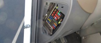
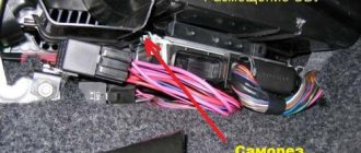
Fuse and relay box in the interior of Lada Kalina 2
The unit is located on the left side of the instrument panel under the steering wheel. To access the unit, pull the lower left corner of the cover to release the left locking point, then the middle and two right locking points. Then release the upper locking points and remove the cover.
Fuse diagram Lada Kalina 2
The table shows a set of fuses for the maximum configuration of the “luxury” version (depending on the set of options, individual fuses from this set may not be used in the “Normal” configuration).
| Number and current* | “Standard” package | Equipment “Norma” and “Lux” |
| F1 (15A) | Ignition Coils, Injectors, Engine Control System Controller | |
| F2 (10/30A) | Daytime Running Lights | Power supply for the body electronics central unit, Driver's door module. |
| F3 (10/15A) | Alarm | Automatic transmission controller power supply, Automatic transmission control drive. |
| F4 (15A) | Airbag system controller | |
| F5 (7.5A) | Terminal 15 devices | |
| F6 (7.5A) | Reversing light | Reverse Light, Automatic Transmission Controller |
| F7 (7.5A) | Canister purge valve, mass air flow sensor/pressure sensor, DC | Canister purge valve, mass air flow sensor/pressure sensor, phase sensor, DC. |
| F8 (7.5A/-) | Direction indicators | Reserve |
| F9 (5A) | Side lights on the starboard side. | |
| F10 (5A) | Parking lights on the left side, Illumination of instruments and keys, License plate lights, Luggage and glove box lighting. | |
| F11 (5A) | Rear PTFs. | |
| F12 (10A) | Low beam and power supply for starboard electric corrector. | |
| F13 (10A) | Low beam and power supply for the left side electric corrector. | |
| F14 | Reserve | |
| F15 (10A) | Rear window washer, Rear window wiper | |
| F16 (-/5A) | Reserve | Driver door module |
| F17 | Reserve | Reserve |
| F18 | Reserve | Reserve |
| F19 (20A/-) | Door lock | Reserve |
| F20 | Reserve | |
| F21 (10A) | High beam, right headlight | |
| F22 (10A) | High beam, left headlight | |
| F23 (-/10A) | Reserve | Right fog lamp |
| F24 (-/10A) | Reserve | Left fog lamp |
| F25 (15A) | Heated front seats | |
| F26 (5A) | Anti-lock brake control unit | |
| F27 (15A) | Cigarette lighter | |
| F28 (15A) | Fuel pump | |
| F29 (20A) | Windshield washer | Windshield washer, Central body electronics unit |
| F30 | Reserve | |
| F31 (-/7.2A) | Reserve | Air conditioning compressor clutch, Automatic climate control system controller |
| F32 (7.5A) | Brake lights, Interior lighting | |
| F33 (25A) | Anti-lock brake control unit | |
| F34 (5A) | Instrument cluster, Diagnostic connector | |
| F35 (-/10A) | Reserve | Central body electronics unit |
| F36 (10A) | Sound signal | |
| F37 (10A) | Radio/Multimedia system | |
| F38 | Reserve | |
| F39 | Reserve | |
| F40 | Reserve | |
| F41 | Reserve | |
| F42 (30A/-) | Electric windows | Reserve |
| F43 (-/50A) | Reserve | AMT controller |
| F44 (30A) | Electric heater fan | Electric heater fan, Automatic climate control system controller |
| F45 (25A) | Heated rear window | |
| F46 | Reserve | |
* — the first value for the “standard” configuration, the second for “norm” and “luxury”.
Fuses located in the mounting block of the vehicle interior with the ERA-GLONASS function (in a variant):
| № | Current strength | Protected Circuits |
| F1 | 15A | Minimum speed radiator fan relay K18 (version with air conditioning or climate control) |
| Maximum speed radiator fan relay K4 | ||
| Air conditioning compressor clutch relay K10 (version with air conditioning or climate control) | ||
| Engine Control System Controller | ||
| Cylinder injectors | ||
| Ignition coils (for 16-valve internal combustion engines) | ||
| F2 | 7.5A | Intake pipe damper valve (for 16-valve internal combustion engine 21127) |
| Canister purge valve | ||
| Oxygen sensors | ||
| Phase sensor (for 16-valve internal combustion engine) | ||
| Mass air flow sensor (for 8-valve internal combustion engine or 16-valve internal combustion engine 21126) | ||
| AMT selector (version with AMT controller) | ||
| Tire pressure monitoring system control unit (terminal 30) (for EURO-6 vehicles) | ||
| F3 | 5A | Anti-Lock Brake Controller / Stability Control Controller |
| F4 | 15A | Airbag system control controller |
| F5 | 7.5A | Starter Relay K2/Automatic Transmission Controller |
| Unloading relay of ignition switch K1 | ||
| Rear window heating relay K6 | ||
| Seat heating relay K13 (optional) | ||
| Heated windshield relay K14 (optional) | ||
| Fuel pump relay K12 | ||
| Engine Control System Controller | ||
| Audio system | ||
| Electric Power Steering Controller | ||
| Wiper switch | ||
| Central body electronics unit (optional) | ||
| Terminal block "ERA-GLONASS" | ||
| Clutch pedal switch (for manual transmission) | ||
| Brake pedal switch | ||
| Instrument cluster | ||
| Door lock system control unit (optional) | ||
| Driver's door lock switch | ||
| Air conditioner switch (optional) | ||
| Automatic transmission speed sensor (optional) | ||
| Automatic transmission mode switch (optional) | ||
| AMT controller (optional) | ||
| Tire pressure monitoring system control unit (for EURO-6 vehicles) | ||
| F6 | 7.5A | Reversing light |
| Direction indicators | ||
| Parking system control unit (optional) | ||
| F7 | 10A | Starboard high beam |
| F8 | 10A | Left side high beam |
| F9 | 5A | Side lights on the starboard side |
| F10 | 5A | Left side marker lights |
| License plate lights | ||
| Trunk light | ||
| Illumination of instruments and keys | ||
| F11 | 5A | Rear fog lights |
| F12 | 10A | Starboard low beam |
| F13 | 10A | Left side low beam |
| Headlight electric adjustment control (optional) | ||
| F14 | 20A | Central body electronics unit: |
| (Windshield wiper) (optional) | ||
| Windshield washer | ||
| Windshield wiper | ||
| Steering column wiper switch | ||
| F15 | 10A | Rear window wiper |
| Rear window washer | ||
| F16 | RESERVE | |
| F17 | RESERVE | |
| F18 | RESERVE | |
| F19 | RESERVE | |
| F20 | RESERVE | |
| F21 | 15A | Fuel pump motor |
| F22 | 7.5A | Brake light switch |
| Brake lights | ||
| Additional brake signal | ||
| Anti-Lock Brake Controller/ Stability Control Controller | ||
| AMT controller (optional) | ||
| F23 | 5A | Instrument cluster |
| Diagnostic connector | ||
| F24 | 10A | Horn relay K8 |
| Sound signal | ||
| F25 | 15A | Socket for connecting additional consumers in the cabin |
| F26 | 5A | Terminal block "ERA-GLONASS" |
| F27 | 10A | Starboard fog lamp (optional) |
| F28 | 10A | Left side fog lamp (optional) |
| F29 | 15A | Heated front seats (optional) |
| F30 | 10A | Audio system |
| F31 | 10A | Central body electronics unit: (Direction indicators; Power supply for body electronics unit) (optional) |
| F32 | 30A | Central body electronics unit: (Power windows; Door and trunk locks; Rain sensor; Glove box light; Trunk light; Interior light unit; Daytime running lights) (in a variant) |
| F33 | 5A | Driver door module |
| F34 | 7.5A | Air conditioning compressor clutch (version with air conditioning or climate control) |
| Controller for automatic climate control system (optional) | ||
| F35 | 15A | Automatic transmission controller (optional) |
| Automatic transmission control drive (optional) | ||
| F36 | 15A | Alarm |
| F37 | 15A | Trunk lock actuator switch |
| Door lock control unit | ||
| 5A | Trunk lock actuator switch | |
| F38 | 10A | Daytime Running Lights |
| F39 | 15A | Cartridge for connecting additional consumers in the trunk |
| F40 | 10A | To the trailer lighting connector |
| F41 | 50A | Heated windshield (optional) |
| F42 | 30A | Heated exterior mirrors (optional) |
| Heated rear window | ||
| F43 | 50A | AMT controller (optional) |
| F44 | 30A | Electric heater fan |
| Controller for automatic climate control system (optional) | ||
| F45 | 30A | Power windows for front doors |
| F46 | RESERVE |
Typical faults
Fuse diagram and relay for Lada Kalina
The reasons why the cigarette lighter does not work can be different. One of them is a blown fuse. It may burn out due to connected devices, such as a compressor or splitter. To eliminate the problem, you need to open the mounting block, remove the burnt fuse and insert a new one. A regular 15 or 20 Amp fuse will do.
The second no less popular malfunction is the antenna contacts that are bent inside the device. If you use the charger frequently, the metal tendrils will unbend over time. To return the device to functionality, the antennae should be slightly bent using a flat-head screwdriver (video author: Andrei Che).
Relay diagram Lada Kalina 2
A set of relays is indicated for the maximum configuration of the “luxury” version (depending on the set of options, individual relays from this set may not be used in the “Normal” configuration).
| Number | Current* | “Standard” package | Equipment “Norma” and “Lux” |
| K1 | 50A | Unloading relay | |
| K2 | 30A | Additional starter relay | |
| K3 | 30/40A | Wiper relay | Radiator cooling fan relay |
| K4 | 30A | Radiator cooling fan relay | |
| K5 | 30A | Turn signal relay | A/C compressor clutch relay |
| K6 | 30A | Power window relay | Heated rear window relay |
| K7 | 20A | High beam relay | |
| K8 | 20A | Horn relay | |
| K9 | 20A | Low beam relay | |
| K10 | -/20A | Reserve | Reverse light relay (in versions with automatic transmission) |
| K11 | 20A | ECM main relay | |
| K12 | 20A | Fuel pump relay | |
| K13 | 20A | Seat heating relay | |
| K14 | 30/70A | Alarm relay | Heated windshield relay |
| K15 | 30A/- | Heated rear window relay | — |
| K16 | 30A/- | Additional alarm relay | — |
* — the first value for the “standard” configuration, the second for “norm” and “luxury”.
Relays located in the mounting block of the car interior with the ERA-GLONASS function (in a variant):
| # | Denomination | Relay purpose |
| K1 | 50A | Ignition switch unloading relay |
| K2 | 30A | Additional starter relay |
| K3 | 30A | Windshield wiper relay (optional) / Auto start relay |
| K4 | 30A | Maximum speed radiator fan relay (optional) |
| K5 | 30A | Turn and hazard warning relay (optional) |
| K6 | 30A | Heated rear window relay |
| K7 | 20A | High beam relay |
| K8 | 20A | Horn relay |
| K9 | 20A | Low beam relay |
| K10 | 20A | Air conditioning compressor clutch relay (version with air conditioning or climate control) |
| K11 | 20A | ECM main relay |
| K12 | 20A | Fuel pump relay |
| K13 | 20A | Seat heating relay (optional) |
| K14 | 70A | Heated windshield relay (optional) |
| K15 | 20A | Alarm relay |
| K16 | 30A | Hazard power relay/reverse light relay (optional) |
| K17 | 30A | Power window power relay/radiator fan relay in auto start mode |
| K18 | 30A | Minimum speed radiator fan relay (optional) |
Why doesn't the cigarette lighter work?
Perhaps the fuse was blown due to too much load from the compressor, charger or cigarette lighter splitter. This is one of the most common and easily fixed problems. You will need to open the fuse compartment cover to the left of the steering wheel and replace the blown one. Typically used before. 15 or 20A regular flag.
Another common reason for the cigarette lighter not to work is the unbending of the metal contacts inside it. For example, you often use a charger or power strip. Because of this, the contacts inside the cigarette lighter are unbent. In order for it to work again, you just need to bend them. This must be done carefully using a thin flat-head screwdriver without shorting the contacts, otherwise the fuse will be blown out.
If you decide to completely replace the cigarette lighter, you will need to dismantle the console from the handbrake to the dashboard with the gearbox casing, only then can you remove the cigarette lighter.
Mounting block of fuses and relays in the engine compartment of Lada Kalina 2
A set of fuses is indicated for the “luxury” version. In other versions, individual fuses from this set may not be used.
| Fuse no. | Current strength | Protected Circuits |
| FF1 | 50A | Heated windshield |
| FF2 | 60A | Generator |
| FF3 | 60A | Generator |
| FF4 | 40A (without air conditioning - 30A) | Electric radiator cooling fan |
| FF5 | 50A | Electromechanical power steering |
| FF6 | 40A | Anti-lock brake control unit |
Fuses located in the fuse box of the engine compartment of a car with the ERA-GLONASS function (in a variant):
| # | Denomination | Protected circuit |
| FF1 | 60A | Generator |
| FF2 | 60A | Generator |
| FF3 | 30A | Electric radiator cooling fan |
| 40A | Electric radiator cooling fan (version with air conditioning or climate control) | |
| FF4 | 40A | Anti-Lock Brake Controller / Stability Control Controller |
| FF5 | 25A | Anti-Lock Brake Controller / Stability Control Controller |
| FF6 | 50A | Electric Power Steering Controller |
Attention!
The relay and fuse diagram may differ depending on the configuration and production date of the vehicle.
Plato personal account: login using login and password
“Platon” (short for “payment per ton”) is a system of collecting compensation for the movement of trucks on federal highways. The measure is mandatory and applies to heavy vehicles with a capacity of 12 tons or more. In simple terms, truck drivers must pay money to the treasury for damaging roads; this money goes towards repairing these roads. To make it convenient, owners of heavy trucks need a Plato personal account. We will explain in detail how to get it and why you need it in this article below.
Registration in your personal account
To register, the user will need a valid phone number and email. To start the procedure, you need to click the “Register” icon on the page lk.platon.ru
The system will prompt you to select your country of residence and type of client:
- individual
- individual entrepreneur
- legal organization
The package of documents required when filling out a personal application form will depend on the payer’s status.
By clicking the “Next” button, the user will be redirected to the “Vehicle Owner Data” section.
1) Individual When filling out a personal questionnaire, the Federal Law indicates the following information:
- last name and first name of the vehicle owner;
- TIN (indicated in the certificate of registration with the tax authorities);
- valid e-mail;
- contact number.
Nothing to burn
If the starter is spinning and sparks are flying, your no-start problem may be related to the fuel system. If your car is fuel injected, there are a number of subsystems that could be the culprit. It's a lot of diagnostic work to figure this out, but there are some things you can check in the garage that can save you money short of a trip to the repair shop.
Here's what you need to check:
Electrical connections:
There are many electrical connections in the fuel injection system. Each fuel injector has a connector on the top. There are connections on the air side of the intake and on the cylinder heads. In general, you should check every electrical connection you can find under the hood to make sure there is a connection.
Fuel pump and relay:
To check your fuel pump, you can do a fuel system pressure test - if you have the equipment. Since most of us don't have this kind of thing, we check the electrical connections first. Check the positive side of the fuel pump with a circuit tester. Be sure the key is in the "On" position. If there is current, proceed to the next step. If not, you should check the fuse. If the fuse is good, your problem is the fuel pump relay.
Fuel filter:
If the fuel pump is working properly and fuel is still not getting into the engine, the fuel filter may be clogged. You should replace the fuel filter every 30,000 km or so anyway, so if you suspect it may be clogged, replace it.
There are many more reasons for engine failure, they will be described shortly.
Source
How to check wiring
You can diagnose electrical equipment using a voltmeter, ohmmeter or multimeter, or special diagnostic stands. Computer diagnostics are also carried out, during which error codes and main indicators of the machine’s on-board network are read. To independently check circuits and troubleshoot electrical faults, one multimeter or signal lamp is enough.
We use a multimeter
Fuses in the on-board network are considered the “weakest” link in terms of durability. In case of emergency situations (for example, in the event of a short circuit), the safety elements “take the blow”, protecting the rest of the electrics and electrical equipment of the machine. Fuses cannot be restored and must be replaced during repairs.
Checking the voltage
Before checking the wiring in the car, it is necessary to measure the voltage of the electrical circuit between individual components and electrical equipment. You can call like this:
- Set the multimeter to voltmeter mode.
- Connect one probe of the measuring device to the “minus” of the battery or to the ground of the machine.
- Connect the second probe to the supply wire of the circuit.
If a certain value appears on the device display, then there is voltage in this section of the electrical circuit. You can compare the values with those required according to the vehicle's owner's manual.
Looking for a short circuit
After measuring the voltage, search for short circuits. This will require either a multimeter or a pilot light. As for the lamp, if the wiring is in good condition and there is no short circuit, it should not light up.
A short circuit in the wiring, as well as a lack of voltage (zero or infinite resistance in the electrical circuit), indicates a malfunction in one of 2 components:
- Consumer - electrical equipment, devices, fuses, blocks.
- Wiring – broken or shorted wires, poor wiring contacts at the point of connection with the consumer.
Checking for a short circuit can also be done in voltmeter mode. To do this, it is necessary to remove all fuses in the area being tested and connect the probe to the terminals of the fuse element. The value “0” on the screen indicates the presence of a short circuit in the circuit. If, when you try to move the wires, voltage appears in the circuit, then the short circuit is caused by the wiring and the wires will need to be replaced.
Checking the quality of grounding
Cars use a single-wire wiring diagram - this means that the “minus” goes to the ground (body) of the car. However, corrosion of metal parts, their oxidation and destruction, “loosening” lead to grounding failure and, as a consequence, to disruption of on-board circuit contacts.
Read more: Transmission oil for walk-behind tractor Neva MB 2
Checking the grounding, as well as other electrical elements of the car, is carried out using a multimeter. The procedure is as follows:
- Disconnecting the battery.
- Connecting one multimeter probe to the body (metal parts) of the car.
- Connecting the second probe to the grounding element or wiring connection.
The value displayed on the device screen should be compared with the factory data (car operating manual). If the values diverge greatly, then it is necessary to restore the grounding - clean the metal at the connection point, check the reliability of the fastening.
Checking the integrity of the circuit
The connection of wires in the electrical circuit of cars is one of the most vulnerable points in the entire electrical system of the car. In addition to the destruction of insulation, loss of integrity and breaks at the connection points, oxidation of the contacts also often occurs here. Defects can be determined not only using a measuring device, but also visually. If the integrity of the circuit is broken precisely at the connection point, then soldering of wires with connectors will be required. Otherwise, you need to find the damaged area, which will require a signal lamp or multimeter.
Toyota Vista SV35, 4WD Full Time › Logbook › Checking fuses with a multimeter
Today was not a good day. I went on business, quite far from home. As soon as everything was done, I got into the car “chick-chick”, that’s it, we arrived. The car won't start. The starter does not work, there is no such “vzhzh, vzhzh”. I can only hear the fan working, the dash lights are on, I hear the fuel pump, it’s trying to pump.
I cleaned the terminals because... The same thing happened once because the terminals were oxidized. Did not help. Next I looked at the fuses. I looked in the car, the main ones seem to be intact.
Cabin fuse diagram:
Underhood fuse diagram:
I checked the fuses, they all seem to be intact, because... I remember that if the fuse died, then there will be a picture like this:
I’m thinking what to do, is it really possible that somewhere the wiring in the dashboard has burned out or a contact, what? I'm calling corefan, because... I remember the other day the same crap happened to him. He says to check the starter fuse again. It is located in the engine compartment, under number 6, at 10A. I checked, it's intact. I decided to replace it with another one that was in the glove compartment, voila - the car started up darling =)
So this method of determining whether a fuse is working is not always good.
I came home and decided to measure it with a multimeter. So, you need to measure by the mustache from above, this is mandatory.
Glushnyak, the fuse died.