Where is the diagnostic connector located on a Chevrolet Niva?
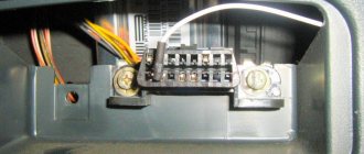
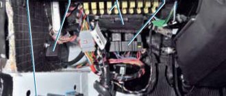
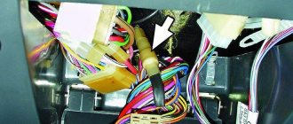
The classic location of the diagnostic connector block in most cars is behind the steering wheel near the ignition switch . Chevy Niva is no exception. The OBD type pinout is used. On-board diagnostics of the first generation was developed back in 1991 with the purpose of reading information on the state of the ECU (electronic control unit). This system is responsible for all engine functions.
The first copies of Niva Chevrolet used a 12-pin OBD1 connector . Since 2002, it was changed to 16-pin OBD2. To select the correct diagnostic equipment for the on-board computer, you need to find out in advance what type of pinout is in a particular Chevrolet Niva.
Additional Information
On some Chevrolet Niva models there is a 12-pin block, this is due to the fact that these models are equipped with other control units of older models. Modern car scanners are mainly based on the OBD2 connector, so to connect to 12 PINs you will need a special adapter purchased or made independently.
The correct connection diagram for a 12 PIN block with a 16 PIN adapter
OBD 1 pinout
To correct the operation of electronic systems, OBD equipment was invented. The first generation pinout has a rectangular shape with 12 pins.
Each element of the nest has its own purpose:
- pin A transmits mass information;
- B corresponds to the diagnostic L-line;
- D—CO potentiometer;
- contact G is responsible for the fuel pump control functions;
- H—food;
- M - K-Line diagnostics.
At the bottom of the pinout there is a “Key” , which is responsible for maintaining the correct design of the equipment. This element is designed to ensure the correct orientation of the plug and connector in the car.
Car brands and years of manufacture
Any injection model before 2002 has an OBD1 pinout. When determining the type of diagnostic connector for 2002 cars, it is worth considering that some may already use OBD2. They can be easily distinguished by their “rosette” shape .
OBD 2 pinout
The 12-pin OBD1 in the Chevrolet Niva has been replaced by OBD2 . This is due to the introduction of new standards in Europe since 2001. This solution has significantly expanded the possibilities of car diagnostics.
The first copies of the equipment showed general error information. Using OBD2, the car owner can independently obtain complete information on the state of the ECU by using a scanning device or adapter. 16-pin connector. Its shape has changed: now it is a trapezoid with a narrowing downwards.
The plug contacts are responsible for the following diagnostic elements:
- pin 2 - bus+ (via J1850);
- 4 — body grounding;
- 5 - signal grounding;
- 6 - CAN-High line (via J-2284 protocol);
- 7 - K-Line;
- 10 — bus- (via J1850);
- 14 - CAN-Low line (via J-2284 protocol);
- 15 — L-line;
- 16 - battery powered.
Car brands and years of manufacture
OBDII has been used in cars since 1996 in the USA. In Europe, standards changed in 2001. In the Chevrolet Niva, new diagnostic connectors first appeared in the 2002-2019 models . These cars work with control systems BOSCH MP7.0 Euro-3, BOSCH M7.9.7, January-7.2, January-7.3.
Access and location
The location remains unchanged : at the ignition switch. OBDII is partially hidden behind the steering wheel cover.
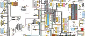
Electrical diagram of Lada 4×4 (VAZ 21213, 21214)
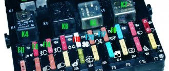
05 November 2015 Lada.Online 166 555 During the operation of the car, problems may arise that can only be solved after studying the electrical circuits. The article presents detailed wiring diagrams for the Lada 4×4 SUV (VAZ 2121), which will help you not only repair the car, but will also be useful when installing additional electrical equipment, for example, a car alarm, DVR and other accessories..
Electrical diagram of VAZ-21213
1 — headlights; 2 — side direction indicators; 3 — electric motor for windshield washer; 4 — headlight washer motor*; 5 - switch; 6 - battery; 7 - starter; 8 - generator; 9 — headlights; 10 — gearmotors for headlight cleaners*; 11 — sound signal; 12 — spark plugs; 13 — carburetor limit switch; 14 — carburetor solenoid valve; 15 — ignition coil; 16 — windshield wiper gearmotor; 17 — carburetor solenoid valve control unit; 18 — ignition distributor sensor; 19 — coolant temperature indicator sensor; 20-oil pressure warning lamp sensor; 21 — plug socket for a portable lamp**; 22 — brake fluid level warning lamp sensor; 23 — windshield wiper relay; 24 — relay for turning on the rear fog light***; 25 — relay for turning on the heated rear window; 26 — relay for turning on headlight cleaners and washer*; 27 — relay for turning on low beam headlights; 28 — relay for turning on the high beam headlights; 29 — ignition relay; 30 — starter activation relay; 31 — relay-breaker for alarm and direction indicators; 32 — heater electric motor; 33 — additional resistor of the heater electric motor; 34 — backlight lamps for heater control levers; 35 — external lighting switch; 36 — main fuse block; 37 — additional fuse block; 38 — reverse light switch; 39 — brake light switch; 40 — instrument lighting regulator; 41 — ignition switch; 42 — three-lever switch; 43 — alarm switch; 44 — tailgate glass cleaner and washer switch*; 45 — heater motor switch; 46 — switch for heating the rear door glass; 47 — rear fog light switch; 48 — lamp switches located in the door pillars; 49 — interior lamps; 50 - cigarette lighter; 51 — switch for the warning lamp for covering the carburetor air damper; 52 — control lamp for covering the carburetor air damper; 53 - switch for differential lock warning lamp; 54 — parking brake warning lamp switch; 55 — sensor for level indicator and fuel reserve; 56 — instrument cluster; 57 — tailgate glass washer motor; 58 — rear lights; 59 — block for connecting additional brake lights; 60 — blocks for connecting side marker indicators; 61 — pads for connecting to the heated glass element of the tailgate; 62 — license plate lights; 63 — gear motor for tailgate glass cleaner.
The order of conditional numbering of plugs in the blocks : a - windshield wipers, headlights and tailgate glass, windshield wiper relay breaker; b — ignition distributor sensor; c — relay-interrupter for alarm and direction indicators; g - switch; d — three-lever switch; e — alarm switch; g — relay for turning on the rear fog light; h — rear lights (numbering of terminals in order from top to bottom); and — instrument clusters.
In the instrument panel wiring harness, the second ends of the white wires are brought together to one point, which is connected to the instrument lighting control. The second ends of the black wires are also brought together to a point connected to ground. The second ends of the yellow wires with a blue stripe are brought together to a point connected to terminal “A” of the main fuse block. And the second ends of the orange wires are also brought together to a point connected to terminal “B” of the main fuse block.
* Installed on parts of manufactured cars; **not installed since 2000; *** installed since 2001. Previously, the rear fog light was switched on directly by switch 47, powered by fuse 3 of the additional fuse box.
Electrical diagram of VAZ-2121
1 — headlights; 2 — side direction indicators; 3 — headlight washer motor*; 4 - voltage regulator; 5 — battery charge warning lamp relay; 6 - battery; 7 - starter; 8 - generator; 9 — headlights; 10 — gearmotors for headlight cleaners*; 11 — sound signals; 12-spark plugs; 13 — carburetor solenoid valve; 14 — ignition coil; 15 — windshield wiper gearmotor; 16 — coolant temperature indicator sensor; 17 — ignition distributor; 18 — windshield washer electric motor; 19 — oil pressure indicator sensor; 20 — oil pressure warning lamp sensor; 21 — brake fluid level warning lamp sensor; 22 — plug socket for a portable lamp; 23 — relay for turning on headlight cleaners and washer*; 24 — relay for turning on low beam headlights; 25 — relay for turning on the high beam headlights; 26 — windshield wiper relay; 27 — additional fuse block; 28 — main fuse block; 29 — additional resistor of the heater electric motor; 30 — reverse light switch; 31 — brake light switch; 32 — heater electric motor; 33 — relay-interrupter for alarm and direction indicators; 34 — parking brake warning lamp switch; 35 — alarm switch**; 36 — cigarette lighter; 37 — switch for cleaners and headlight washers*; 38 — heater motor switch; 39- external lighting switch; 40 — three-lever switch; 41 — ignition switch; 42 — instrument lighting switch; 43 — lamp switches located in the door pillars; 44 — interior lamps; 45 — oil pressure gauge with insufficient pressure warning lamp; 46 — fuel level indicator with reserve warning lamp; 47 — tachometer; 48 — parking brake warning lamp; 49 — battery charge indicator lamp; 50 — control lamp for the carburetor air damper; 51 — side light indicator lamp; 52 — turn signal indicator lamp; 53 — control lamp for high beam headlights; 54 — speedometer; 55 — carburetor air damper warning lamp switch; 56 — relay-interrupter for the parking brake warning lamp; 57 — coolant temperature indicator; 58 — brake fluid level warning lamp; 59 — differential lock warning lamp; 60 - switch for differential lock warning lamp; 61 — rear lights; 62 — license plate lights; 63-sensor for level indicator and fuel reserve.
Diagnostic connector pins for used protocols
The OBDII standard suggests the possibility of using 5 diagnostic protocols . Chevrolet Niva uses 3 of them:
- J1850 PWM. High-speed protocol with a performance of 41.6 Kb/sec. Transmits signals via pins 2, 4, 5, 10, 16.
- J1850 VPW. (The principle) of transmitting signals via pins 2, 4, 5, 16 is the same, but the speed is 10.4 Mb/s.
- ISO 9141-2. The simplest protocol that does not require complex communication microprocesses (unlike the above). Performs pulse transmission using pins 4, 5, 7, 15, 16
Features: The ISO 9141-2 protocol is easy to determine, thanks to pin 7, as well as the exclusion of pin 2 (10) on the Chevy Niva diagnostic connector.
If the system does not have pin 7, the SAE J1850 VPW (Variable Pulse Width Modulation or Pulse Width Modulation) protocol is used.
The specified signal transmission protocols function properly via a standard OBD-II J1962 connector cable.
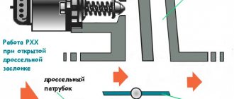
Wiring diagram of the VAZ Niva, the part responsible for powering the head optics
- 1 – main lighting device;
- 2 – fuse box;
- 3 – headlight switching regulator;
- 4 – part of turning off the ignition;
- 5 – headlight switches;
- 6 – designation in the instrument cluster of the area responsible for turning on the high beam;
- K4/5 – protective relays for turning on the high- and low-range modes of the head optics;
- A – terminal pins going to the circuit’s power source.
( 1 rating, average 5 out of 5 )
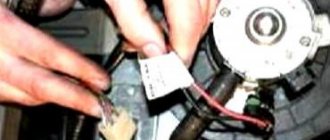
Selecting equipment for diagnosing Niva Chevrolet
The first step when choosing a cable for reading information from an on-board computer is determining the type of connector.
The main difference between OBDI and OBDII (besides the year of manufacture of the vehicle in which it is installed) is the shape of the connector. How to determine what type of pinout is used in a particular car is described in detail above. It is also possible to connect the K-Line connector to the OBD connector on the Niva Chevrolet. In this way, special diagnostic equipment is installed.
To read information from the OCU you will need:
- a scanning device that supports the required type of connections (currently, in addition to traditional equipment operating via a USB cable, there are items that support wi-fi and bluetooth functions);
- laptop;
- adapter (if necessary);
- appropriate software for diagnostics (for the Russian automotive industry, the ScanMaster ELM 2.1 and OpenDiagPro programs are recommended).
Important! The computer must support the same types of information transfer as the adapter. Otherwise, connection will not be possible.
There is a wide range of diagnostic equipment on the modern market . It is divided into the following types:
- "amateur" equipment;
- multi-brand (multifunctional) devices;
- professional equipment.
The last two categories are used for work at service stations and dealerships . For self-diagnosis, it is enough to purchase a simple adapter for beginners based on the ELM327 chip.
Even the most minimally functional equipment is capable of performing all basic tasks (detecting an error, correcting it, transmitting information about the state of the ECU to the PC screen). Such a service in service centers costs up to 1,500 rubles. Purchasing an adapter will save the Niva owner from the need to contact specialists and save money.
Carefully! There are cases when the controller generates an error even though it is fully operational. The reason is the failure of the scanning device itself.
Self-diagnosis
The function involves shutting down the system in which the breakdown occurred, followed by enabling a bypass program . A "Check Engine" light on the dashboard should worry the owner of a Chevrolet Niva. The developers have provided a standard self-diagnosis function. This option is useful in cases where there is a short-term failure in the program, but the machine continues to operate as normal. You can identify an “accident” using self-diagnosis.