Installing an emergency warning light on a VAZ 2101 Many people wondered how to install an emergency warning light on a VAZ 2101 and its modified versions, since serial “hazard warning lights” began to be installed on cars of the Volzhsky Automobile Plant only starting with later models.
Emergency button for VAZ 2101
But sometimes you simply cannot do without this simple device on the road. In addition to its direct purpose, the hazard warning light can be used to thank the driver who let you pass, to park for a short time without formally violating traffic rules, and in general it helps to do all sorts of useful things. So, if you have finally decided to take this significant step for you and your car, then first, here is a list of necessary materials and accessories:
Lada 2101 (yomobile) › Logbook › Emergency light on VAZ 2101
In this material I will try to help owners of classic Lada models 2101, 2102 and 2103 acquire such a useful and necessary thing as an Emergency Light Alarm, or in common parlance - an emergency gang! For some reason, the manufacturer itself deprived these models of this device. But the problem can be solved. Searching for solutions on the Internet only led to advice to take circuits 2101 and 2106 and do the same. But not everyone has these two diagrams at hand, and many simply don’t want to figure out what’s there and how. I will present the finished version with pictures and photographs. I have not found such material.
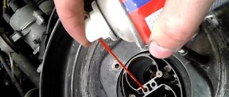
First, we remove the instrument cluster in order to get to the turn signal relay.
And remove the old relay (looks like a silver barrel)
three wires are connected to it: purple, blue and double orange
We mark and secure the wires so as not to lose them
Next, we take a new relay (I recommend 494.3747 as a more modern digital one, as opposed to the analog 231.3747)
this relay has four legs
Additional items
Under the hood
Additional headlight wiper fuses (2A rating) protect the motor windings. They are located on the supply wires next to the gearmotors.
p, blockquote 18,0,0,0,0 —>
p, blockquote 19,0,0,0,0 —>
The starter activation relay 113.3747 or 90.3747-10 is located in the engine compartment on the right mudguard.
p, blockquote 20,0,0,0,0 —>
p, blockquote 21,0,0,1,0 —>
In the cabin
The windshield wiper relay (PC-514) is mounted under the panel on the left under the trim.
p, blockquote 22,0,0,0,0 —>
p, blockquote 23,0,0,0,0 —>
The ignition relay and the hazard warning and turn signal relays are installed on the front panel behind the instrument panel. The ignition relay (113.3747-10 or 90.3747-10) and the hazard warning and turn signal relays (23.3747 or 231.3747) have a bracket for direct mounting on the body.
p, blockquote 24,0,0,0,0 —>
p, blockquote 25,0,0,0,0 —>
The fog lamp fuse is located in the gear shift compartment, not far from the radio.
p, blockquote 26,0,0,0,0 —>
p, blockquote 27,0,0,0,0 —>
Turn relay VAZ 2101 connection diagram.
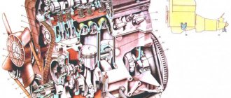
The turning pattern of the VAZ 2101 is based on the electromagnetic-thermal RS57. The principle of connecting the VAZ 2101 turn relay is quite simple and applied to all cars that were produced in those years. The VAZ 2101 electromagnetic-thermal turn relay, type RS57, consists of a core with a winding, a panel, two armatures, a nichrome string, a resistance and two pairs of contacts. The left armature with a pair of contacts opens and closes the circuit of signal lamps, and the right armature with its contacts ensures the operation of the indicator lamp.
Fuse and relay box
The main block with fuses and relays is located under the hood and can be made in 2 versions (old and new). The current diagram will be printed on the block cover.
p, blockquote 3,0,0,0,0 —>
Option 1
p, blockquote 4,0,0,0,0 —>
Scheme
p, blockquote 5,0,0,0,0 —>
p, blockquote 6,0,0,0,0 —>
Option 2
Installed on cars of early production years, here the fuses are cylindrical.
p, blockquote 7,0,1,0,0 —>
p, blockquote 8,0,0,0,0 —>
Scheme
p, blockquote 9,0,0,0,0 —>
p, blockquote 10,0,0,0,0 —>
Description
Circuit breakers
p, blockquote 11,0,0,0,0 —>
| 1 | 8/10A Heater motor Reversing light lamps Rear window heating switch on Rear window heating switch relay (winding) Rear window wiper motor (2104) Rear window washer pump motor (2104) |
| 2 | 8/10A Windshield wiper and washer motor Headlight wiper and washer motor Windshield wiper relay Headlight wiper and washer relay |
| 3 | 8/10A Reserve |
| 4 | 8/10A Reserve |
| 5 | 16/20A Rear window heating element and heating relay |
| 6 | 8/10A Cigarette lighter Socket for portable lamp Clock |
| 7 | 16/20A Sound signals Signal relay Electric radiator cooling fan relay (contacts) Radiator cooling fan electric motor |
| 8 | 8/10A Hazard switch with warning lamp Relay-breaker for direction indicators and hazard lights Turn signal indicator (in hazard mode) Turn indicators (in hazard mode) |
| 9 | 8/10A Generator Voltage Regulator |
| 9 | 8/7.5A Rear fog lamps and their indicator |
| 10 | 8/10A Turn signals (in turn signal mode) Relay - turn signal switch Turn signal indicator Pneumatic valve control system Tachometer Fuel gauge Fuel reserve indicator Parking brake indicator Insufficient oil pressure indicator in the engine lubrication system Coolant temperature indicator Voltmeter Service brake emergency indicator systems Battery charge indicator Carburetor air damper closed indicator Electric fan relay (winding) Electric fan thermal switch Generator excitation winding (generator 37.3701) |
| 11 | 8/10A Interior lamp Brake lamp Luggage compartment lamp |
| 12 | 8/10A High beam headlights (right headlight) Relay for windshield wipers and headlight washers (relay coil) |
| 13 | 8/10A High beam headlights (left headlight) High beam indicator |
| 14 | 8/10A Front side light (left headlight) Rear side light (right light) License plate lights Engine compartment lamp Side light indicator |
| 15 | 8/10A Front side light (right headlight) Rear side light (left light) Cigarette lighter lamp Instrument lighting lamp Glove box lighting lamp Clock (lighting lamp) |
| 16 | 8/10A Low beam headlights (right headlight unit) Relay for windshield wipers and headlight washers (relay coil) |
| 17 | 8/10A Low beam headlights (left block headlight) |
| 18 | Spare |
| 19 | Spare |
| 20 | Spare |
| 21 | Spare |
The cigarette lighter is controlled by fuse number 6 at 8 or 10A.
Relay
Installation and connection of emergency lights on the Kopeyka - VAZ 2101: recommendations + diagram
All modern cars are equipped with hazard warning lights, which cannot be said about older cars. For example, in this article we will talk about the legendary Russian “Kopeyka” - VAZ 2101. Since these cars are not equipped with a warning light, car owners have to install it themselves. What is the wiring diagram for the emergency lights on the VAZ 2101 and how to correctly carry out this task - read on.
VAZ turn signal relay - do-it-yourself diagnostics and replacement
Turn signals are perhaps a very important part of any vehicle. Carrying out maneuvers on the road becomes quite a dangerous task if the turn signals do not work. The VAZ 2107 turn signal and hazard warning relay is responsible for the correct operation of the direction indicators. This device is used on all cars of the classic family. Let's consider why a turn signal relay is needed, how is a relay malfunction determined and how is it replaced?
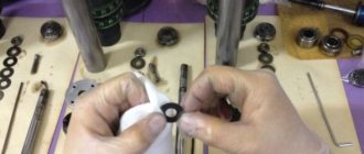
Materials:
1. Electrical tape (preferably blue, as it is especially durable) 2. Four-pin turn signal relay from VAZ 2106 3. Relay connector 4. Six-pin alarm switch off button 5. Connector for the button 6. Wire for mounting and connecting the above. Tools: 1. Pliers with wire cutters 2. Flat-head screwdrivers 3. Phillips screwdrivers 4. Open-end wrench 10 5. Knife For those who want to save money at the expense of manufacturability: you can use the original relay from the VAZ 2101, but in this case it will work adequately not guaranteed as this relay is very sensitive to load changes. For this reason, the following installation method involves replacing the relay with a more modern one. Let's get started, unscrew the nut securing the turn signal relay and disconnect three multi-colored wires from it. Next, we determine where to install the hazard warning button. Here we give freedom to our imagination, but a lot also depends on what kind of panel is installed in your car. To the second contact of the relay we connect the wire removed from the contact of the old relay, marked with the letter “L”, and connect all this to the seventh contact of the alarm button. We connect the first contact of the emergency light relay to the fourth contact of the button. We connect the third contact of the relay with the wire removed from the “P” contact of the old relay. We attach the wire coming from the fourth contact of the relay to the car body. The optimal solution would be to secure the wire under the fastening nut of our relay.
Scheme of emergency lights (hazard warning lights) for VAZ 2101 → Get useful materials for VAZ 2101-2110 Thank you for subscribing!
Now tighten the relay mounting nut with moderate force so as not to break the plastic mount. Then we connect the second contact of the button to the positive wire of the old relay. We connect the first and third contacts of the button to the steering column turn signal switches in any order. The eighth contact of the button is connected to a constant “plus” (independent of the position of the key in the ignition switch). It is advisable to protect this circuit with a fuse. The most suitable would be to install a fuse rated 8A. Next, you should wrap the wires with electrical tape and secure them so that they do not dangle, and install all the previously removed casings and panels. Now we have a full-fledged alarm system and can live a new, full life. The entire procedure for installing an alarm system on a VAZ 2101 takes 2-3 hours.
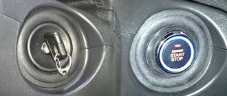
Installation and configuration instructions
Installing emergency lights on a VAZ 2101 is not a particularly difficult task; almost anyone can cope with it. To properly connect the emergency lights to a VAZ 2101 with your own hands, you need to prepare everything you may need to complete the task.
Set of tools and materials
So, what you need to prepare before starting the process:
- Locksmith tools, including wrenches, screwdrivers, pliers, etc.
- Insulating tape.
- Four-contact light signal relay from the “Six”.
- Six-pin button for activation.
- Five meters of installation wire (video by Alex Gordon).
Work execution algorithm
So, let's start the process:
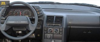
- First you need to remove the center console. To do this, you need to unscrew the bolts that secure the trim to the steering column. You will also need to remove the side trims of the windshield pillars.
- Having done this, you can remove the instrument cluster. Be careful not to damage the device.
- Next, disconnect the wires from the light bulb that illuminates the glove compartment. Then unscrew the bolts that secure the sides of the glove compartment to the control panel, as well as the bolts that secure its lower part. After unscrewing all the screws, the glove compartment itself can be removed.
- Now you need to remove the screws that secure the bottom of the dash to the front cross member. Then the nuts of the upper fastening are unscrewed; it is best to reach them through the technological opening of the glove compartment.
- After completing these steps, you can remove the handles from the stove control panel. To do this, at the junction of the lever with the handle, use a screwdriver to bend the lower part of the upper handle, and at the lower handle, you need to bend the upper part.
- Next, you need to disconnect the connectors with wires from the control panel backlight switches, side lights, and also the stove. Then, using a wrench, you need to unscrew two more bolts that secure the fastenings of the stove control levers. After completing these steps, you will be able to dismantle the control panel.
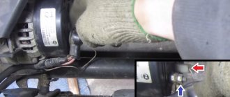
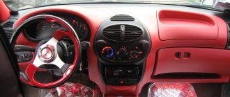
- Now let's move on to installing and connecting the main elements. First, decide on the location of installation of the system power button. It should be installed on the center console so that the driver can reach it as quickly as possible if necessary. It’s still too early to install the button, but you need to decide on the installation location now, since this will determine how much wire you need. Now remove the old turn signal relay from the car and disconnect the three cables from it - usually they are colored black, gray-white and orange.
- Next, take a new six-wheel relay. The second contact of the relay must be connected to the wire that was removed from contact L on the turn signal relay, as well as to output 7 of the button.
- The first contact of the relay must be connected to the fourth contact on the button itself. The third contact is connected to the cable disconnected from contact P on the turn signal relay. Then you need to connect the cable from the fourth contact to ground, that is, the body of the vehicle - it is best to connect it to the relay fixing nut.
- The next step is to connect the button itself. The fourth contact of the button should be connected to the first contact of the relay used. Its second contact must be connected to the cable that was disconnected from the positive contact of the rotary relay. The seventh contact is connected to the second contact of the relay, and the first and third contacts are connected to the steering column turn signal switch; in this case, the order of connection does not matter.
- Now all you have to do is connect the eighth pin to any positive cable; alternatively, you can wedge it into the electrical circuit from the cigarette lighter. If you decide to connect the plus directly to the battery or generator unit, the circuit will need to be protected with a fuse.
- At this point, the installation procedure can be considered complete. All you have to do is securely fix the wiring to prevent chafing of the cables. Reinstall all previously removed interior trim elements, center console, glove compartment, etc.
Photo gallery "Electrical circuits"
1. Relay connection diagram
2. Diagram of a penny turn switch
Price issue
The cost of an emergency warning button for a Kopeyka ranges from 100 to 400 rubles on average. As for the relay, its cost varies around 200-400 rubles.
Have you encountered problems with wiring in your car?
Survey
- Yes
- No
- I don’t know (I don’t repair my car)
Loading …
Turning relay VAZ 2101 replacement with an electronic relay.
If desired, you can replace the electromagnetic-thermal relays of the VAZ 2101 with an electronic relay used on VAZs of subsequent brands. The connection is made in almost the same way. In addition to the standard wires, it is necessary to add only one wire connecting the electronic relay to the vehicle ground. In this case, you can also connect an alarm button.
admin 26/11/2013
“If you notice an error in the text, please highlight this place with the mouse and press CTRL+ENTER” “If the article was useful to you, share the link to it on social networks”
Installation of alarm systems on VAZ 2101 and their modifications
Installation of alarm systems on VAZ 2101 and their modifications.
I think that many people have had the desire to equip their car with an alarm system. After all, if anyone doesn’t know, the emergency warning system began to be installed on cars of the VAZ family starting with model 2103. But you must admit that sometimes you want to flash the emergency lights to the person who let you pass in a traffic jam, wink at a pretty girl, or simply, almost legally, stop at public transport stop in front of the trolleybus and run to the stall almost without violating traffic rules...
So, for those who are interested in all of the above...
Replacing turn signal and hazard warning relays (+ Video)
After detecting any of the listed malfunctions, the turn signal relay must be replaced. Depending on the modification (carburetor or injector), the location of the breaker relay may differ noticeably. Carburetor VAZ 2107 vehicles require installation of the relay behind the dashboard in the vehicle interior. However, starting with an injection engine, the relay can be located in a mounting block in the engine compartment.
In order to remove the relay located in the mounting block, you just need to pry it up and pull it up. After this, a new element is installed in its place.