The operation of electrical equipment in any modern car directly depends on the performance and integrity of the wiring. That is why every car owner must understand the electrical circuit of the car. In particular, we are talking about the legendary domestic UAZ cars. What the electrical circuit of the old-style UAZ-3303 is and what malfunctions are typical for it - we will talk about this below.
Nuances of electrical equipment
The electrical circuit of the on-board wiring for the UAZ 390945 includes the following systems:
- Ignition. This system consists of different elements - a distributor, a coil, spark plugs, high-voltage wires through which the charge is transmitted.
- Safety block. This unit is a set of safety devices designed to protect the electrical circuits of installed devices and electrical equipment.
- Glass washer. The washer system consists of windshield wiper blades, a trapezoid, an electric pump, an expansion tank, a gearbox and other components. The main purpose is to ensure high-quality cleaning of the windshield.
- Acoustics. Its presence is not relevant for all vehicles. The acoustic audio system includes a car radio, speakers, and an antenna adapter.
- Rear window heating system.
- Optics.
The operation of any circuit involves the use of a battery, as well as a generator device. The first is used to provide power to all equipment when the engine is turned off, and the second is used to power the battery, as well as power electrical devices when the engine is running (the author of the video is the Protect Your Interests channel).
Electrical equipment UAZ 3151, 2206
Rice. 7.5. Electrical diagram of a UAZ-33036 car without multifunctional steering column switches: 1, 6 – front lights;
2, 5 – headlights; 3, 4 – fog lights; 7 – switch for warning lamp for brake system malfunction; 8 – sound signal; 9 – windshield wiper;
10 – brake light switch; 11 – direction indicator switch;
12 – electric washer; 13 – heater resistance; 14 – fog lamp relay; 15, 16 – headlight switching relay; 17 – fuse for fog lights 10 A; 18 – relay for direction indicators and hazard warning lights;
19 – headlight switch; 20 – heater electric motor; 21 – cigarette lighter; 22 – cigarette lighter fuse 16 A; 23 – windshield wiper switch; 24 – sound signal button; 25 – cabin light switch; 26 – thermal fuse 20 A; 27 – fuse block; 28 – plug socket; 29 – cabin heater switch; 30 – external lighting switch; 31 – rheostat for instrument lighting; 32 – speedometer; 33 – voltage indicator; 34 – oil pressure indicator; 35 – coolant temperature indicator; 36 – fuel level indicator; 37 – rear fog lamp switch; 38 – control lamp for high beam headlights;
39 – indicator lamp for direction indicators; 40 – indicator lamp for turning on the parking brake; 41 – warning lamp for brake system malfunction; 42 – warning lamp for emergency oil pressure; 43 – warning lamp for emergency coolant temperature; 44 – ignition switch;
45 – control unit EPPH; 46 – fog lamp switch; 47 – alarm switch; 48 – cabin lighting; 49 – generator; 50 – emergency oil pressure sensor; 51 – oil pressure sensor; 52 – coolant temperature sensor; 53 – emergency coolant temperature sensor; 54 – transistor switch; 55 – emergency vibrator; 56 – parking brake warning lamp switch; 57 – additional resistance; 58 – starter relay; 59 – electromagnetic valve EPPH;
60 – unbalance solenoid valve; 61 – microswitch;
62, 63, 64, 65 – spark plugs; 66 – sensor-distributor; 67 – ignition coil; 68 – side repeater; 69 – fuel level sensor switch;
70 – starter; 71 – battery; 72 – ground switch; 73 – reverse light switch; 74 – side repeater; 75, 76 – fuel level sensors; 77, 82 – rear lights; 78, 79 – license plate lights;
Possible wiring problems
What can lead to wiring problems:
- Broken wires or damaged insulation. In both cases, the only option is to replace the damaged section of the electrical circuit. An open circuit, as well as chafing of cables, can be caused by external factors, for example, if the wiring was laid where there are rubbing mechanisms. Before replacing the cable, it is necessary to eliminate the cause, otherwise the problem will soon occur again. Solving the problem of insulation chafing by wrapping several layers of insulating tape onto the cable is also impractical.
- Short circuit in the system. Such a malfunction can only be determined by diagnosing the electrical circuit using a tester - a multimeter. A short circuit can also be caused by chafing of power cables.
- Voltage surges. Such malfunctions may be caused by the use of too powerful energy consumers. Let's consider the simplest example: you installed a splitter into several sockets into the cigarette lighter socket. When the voltage consumers are turned on, a higher current charge is supplied to each socket of the cigarette lighter. The cigarette lighter socket is designed for a certain voltage, and if instead of one device two or three devices are powered, then, accordingly, the voltage passing through the socket will be several times higher. This contributes to the appearance of differences in the operation of the electrical system.
- Failure of the safety device. If the fuse blows, it is necessary to replace the failed element. But if burnout occurs too often, then you need to check the socket in which the part is installed. Perhaps the reason lies in voltage surges, so the fuse blows prematurely. The cause of the difference must be eliminated.
- Generator unit malfunction. Problems in its operation can be identified by reduced voltage in the on-board network, as well as dim headlights. Moreover, when the driver presses the gas pedal, the brightness of the optics increases noticeably. This usually indicates a failure of the voltage regulator or worn brushes.
- Oxidation of contacts at the ends of wires. Due to oxidation or damaged contacts, power to electrical equipment is disrupted because charge cannot flow to the device. The problem of contact oxidation may be a consequence of exposure to moisture on the wiring. This problem can be resolved by cleaning the contacts or replacing them. You can use fine-grit sandpaper for cleaning.
Schematic features
UAZ 390345, 315314 and analogues in the general wiring have high-quality and reliable components. These are the following types of alarms:
- parking brake;
- level of brake fluid used;
- turning on headlights for high beam;
- switching on for turn signals;
- cooler overheating;
- emergency oil pressure;
- coolant temperature;
- oil pressure and fuel level readings.
All of them are distinguished by a high level of reliability, quality, and durability of use. The wiring includes a microswitch for the carburetor (for model 390994, an injector and the necessary sensors for it), an EPHH valve of the electromagnetic type. The following sections of the circuit are provided for lighting:
- central light switch;
- interior lamp;
- right, left steering column switch;
- fuel level sensors, rear light;
- fog rear lights;
- license plate light;
- reversing lights.
Separately, the electrical circuit of the UAZ 390994 (315314) has such points as power for the cigarette lighter, trailer socket, bimetallic (that is, thermal) fuse. It must be remembered that such wiring for the UAZ 390945 trailer socket is not available on all models, but only on some. If necessary, you can connect additional equipment.
How to determine the malfunction?
If there are problems with the electrical wiring, this can be determined by the following symptoms:
- The generator unit has stopped producing charging current. That is, the electrical equipment has either stopped being powered, or the current in the network is too low. Such a malfunction may be accompanied by noise during the operation of bearing devices.
- There are malfunctions in the operation of the starter mechanism. Now the device cannot crank the engine crankshaft, the rotor assembly can rotate, but the crankshaft does not turn. When you try to start the power unit, relay clicks may be heard. Also, the inoperability of the starter may manifest itself in the fact that the car engine starts, but after that the starter unit does not turn off.
- Another symptom of a wiring malfunction is the rapid discharge of the car battery. If the battery is relatively new and has not yet exhausted its service life, then its rapid discharge should alert the car owner. If after the next charge the battery still quickly discharges, you need to look for the reason. A malfunction in the operation of the battery can be indicated by a decrease in the volume of working fluid in the jars and an increase in its density during charging.
Electrical circuit elements
The electrical circuit of the domestic UAZ is simple, since it is of the single-wire type. The standard wiring diagram for a UAZ “loaf” with a carburetor has the following features:
- the car body serves as a mass,
- The electrical diagram of the UAZ loaf with a carburetor and the actuators are equipped with a negative terminal connected to the housing.
The second feature is considered by experts to be an imperfection of this scheme.
Meet UAZ 452
The car was a cargo-passenger version of an off-road vehicle with a 4x4 wheel arrangement. The Ulyanovsk Automobile Plant mastered production of the model back in 1965.
You can evaluate its capabilities by watching the following video:
The UAZ 452 is capable of transporting cargo weighing up to 700 kg in the back. In addition, it can tow a trailer weighing 850 kg. The vehicle became very popular not only in Russian off-road conditions, but was also successfully used in large cities in various capacities (pictured in the article).
In particular:
- Like a traffic police car;
- As a fire engine;
- Ambulance car;
- Grocery store;
- Utility vehicle, etc.
The famous Barefoot on the basis of UAZ 452 - a road train in the Izmailovo Central Park of Culture and Culture
Electronic components
Modern color wiring diagram of the UAZ 452
The electrical wiring of the UAZ 452 was a simple single-wire circuit.
Structurally, it had the following solutions:
- The role of the second wire was played by the metal body and the components and assemblies attached to it;
- All electronic components and actuators had a “-” displayed on the housing. The cost of such a solution justified the imperfection of the scheme.
For reference: The instructions provided for regular checking of contacts. When oxidized, they should have been cleaned with sandpaper.
Power unit
The engine compartment is located directly inside the car, as this is due to its design.
Access to components and assemblies is also provided from the passenger compartment by removing the cover, which:
- Provided protection for the driver and passengers from the penetration of exhaust gases;
- Protected from dust and dirt;
- Served as an additional heating element (passive - from heating).
The high layout of the engine contributes to the vehicle's cross-country ability in off-road conditions.
The previously used engine from the Pobeda was replaced with a more modern engine from the 21st Volga. This was facilitated by the launch of a production line at the Zavolzhsky Motor Plant in 1964.
Note! Despite some skepticism regarding the inconvenience of servicing a cabover car with your own hands, years of operation have proven that there are no difficulties.
Passive vehicle safety
The design of the "Baton" with a cabover layout also initially raised a number of questions regarding safety. However, a series of crash tests conducted back in 1971 at the Dmitrov test site proved that in most emergency situations the driver and passengers of the UAZ 452 have a chance to avoid injury.
A striking example of comprehensive testing of “Tablets”
Features of the equipment in the diagram
The start of production of the UAZ automobile was complicated for the designers of the Ulyanovsk plant in the search for high-quality components. This problem especially applies to lighting and ignition systems, so the company’s engineers were forced to use non-standard solutions to establish mass production.
Therefore, the wiring diagram of a UAZ loaf with a carburetor includes an optics switch from an older GAZ-69 car.
Domestic cars from time to time puzzle users with problems with electrical equipment. If the electrical wiring of your UAZ is not functioning correctly, you will have to check not only it, but also the other elements of the circuit.
First of all, the functionality of the fuses located in the installation unit is checked. Then the integrity of the lamps is checked, and the tester rings the electrical part.
I have a 1989 car, originally it had a contactless ignition system. Later it was converted to contact, which in principle I do not regret. And each has its own pros and cons. We’re not talking about them. I had to use the old-style UAZ 3303 wiring diagram, of course, with a carburetor.
The plant immediately warns about the possibility of making changes to the electrical circuit. Since the car is almost 30 years old, there are such changes. I will give several diagrams with contact and non-contact ignition systems for different UAZ vehicles. But since in those days there were no special differences, I consider them similar with some differences.
Features of the modification with multifunctional control
Variations with the car body did not greatly affect its technical equipment. But when changes affected the governing bodies, they underwent modernization:
- Interior wiring for UAZ;
- Steering column control unit for turns and exterior lighting;
- Control unit for the operation of electric windshield wipers on the instrument panel.
Reason for modernization
For reference: according to pan-European safety requirements, when activating light and sound devices while driving, the driver of the vehicle must not remove his hands from the steering wheel. Based on this principle, the wiring diagram for the VAZ 2112 and other models of the Tolyatti Automobile Plant is built.
On cars of the UAZ family, the windshield wiper control unit was located on the instrument panel. And since this did not meet safety requirements, then on all subsequent modifications:
- it was replaced with a more modern multifunctional unit located directly on the steering wheel;
- They began installing a new instrument panel.
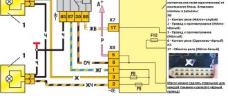
Electrical wiring diagram
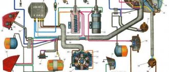
The top picture shows a non-contact version of the car's electrical wiring in color; the bottom picture shows an older model.
Old style UAZ 3303 wiring diagram
The electrical circuit of the UAZ 3303 generator shown separately is shown above.
The circuit having an ignition system with contacts is taken from 469. There is a radio receiver on the circuit, this is interesting.
Electrical circuit of UAZ 469 similar to 3303 with contact ignition system
In conclusion, I present another one from an onboard UAZ 33036 that is newer, but not yet fuel-injected.
