07/19/2021 26 319 VAZ Niva
Author: Ivan Baranov
If any equipment on a car fails, the first thing you need to do is check whether the fuse is intact. This is not difficult to do and even a novice motorist can do it, and there is no point in going to a service station for this. A simple replacement can cost you a pretty penny. To do this, just find the VAZ 2121 Niva fuse box, which the designers placed in a very accessible place.
Electrical fuses on cars are changed if they blow out, without fail observing their rating. But other situations also happen on a VAZ 2121 Niva. For example, many motorists complain that sometimes electrical fuses simply fall out of the block. That is why it is recommended to replace the old unit with a new one, in which the safety elements hold up much better.
VAZ 2121 – Niva [Hide]
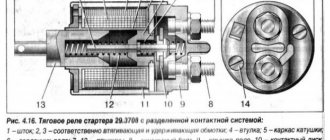
Fuses and relays Niva 2121
The cars Niva 2121, Niva 21213, Niva 21214 carburetor, injector were considered.
another name for VAZ 2121, VAZ 21213, VAZ 21214, Niva 4x4.
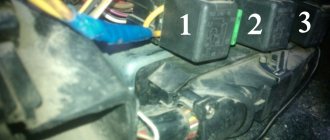
Location of fuses and relays Niva.
The main fuse box is located in the passenger compartment under the instrument panel, to the left of the steering wheel.
1 — engine control system fuse block; 2 — windshield wiper relay; 3 — fuse blocks; 4 - engine control system relay block
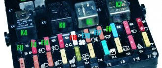
Main and additional fuse box Niva.
To access the blocks, pull the latch located on top of the blocks and remove the cover.
Fuse designation (rated current, A)
Heater Blower Motor Switch, Tailgate Defroster Switch, Tailgate Wiper Motor, Tailgate Wiper/Washer Switch (Windshield Washer Pump)
Steering column switch, windshield wiper motor, hazard warning switch, breaker relay (in turn signal mode), reverse light switch, instrument cluster (coolant temperature gauge, fuel level gauge, tachometer, indicator lamps: turn indicators, differential locks, parking brake, emergency condition of the service brake system, insufficient oil pressure, fuel reserve, battery charge)
Left headlight (high beam), high beam indicator lamp
Right headlight (high beam)
Left headlight (low beam)
Right headlight (low beam)
Side light lamps in the left front and left rear lights, license plate lights, side light indicator lamp
Side light lamps in the right front and right rear lamps, backlight lamps for the instrument cluster, cigarette lighter, switches, heating and ventilation control unit
Hazard switch, breaker relay (in hazard mode), heated tailgate glass relay contacts
Sound signal, interior lamps, brake lamps in the rear lights
Fog light relay contacts in rear lights
Source
Where is the DTOZH of the VAZ 2123 engine?
The coolant temperature sensor is an electrical resistor with a built-in thermometer. The device is called a thermistor. The principle of operation is simple: when the temperature changes, the resistance changes, which affects the executive part of the system. To measure the thermistor, use a multimeter set to resistance.
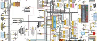
Connection diagram of the VAZ-21214 engine management system with central fuel injection under US-83 toxicity standards with controller 21214-1411010 (EFI-4 type) on VAZ-21214 vehicles: 1 - “CHECK ENGINE” control lamp; 2 — instrument cluster (fragments); 3 — electric fans of the engine cooling system*;
4 — electric heater of the intake pipe; 5 — air temperature sensor; 6 — absolute pressure sensor; 7 — coolant temperature sensor; 8 — block connected to the throttle position sensor; 9 — central fuel injection unit; 10 — block connected to the idle speed regulator;
11 — block connected to the nozzle; 12 — diagnostic block; 13 - controller; 14 — knock sensor; 15 — speed sensor; 16 — oxygen concentration sensor; 17 - adsorber; 18 — battery; 19 - main relay; 20 — fuse block of the engine control system; 21 — relay for turning on the electric fuel pump;
22 — relay for turning on the electric fan*; 23 — relay for turning on the electric heater of the inlet pipe; 24 — electric heater protection fuse; 25 — starter activation relay; 26 — ignition relay; 27 — main car fuse box (fragment); 28 — spark plugs; 29 — tachometer; 30 — electric fuel pump with fuel level sensor;
31 — ignition module; 32 — crankshaft position sensor; 33 - courtesy light switch, located on the driver's door pillar; 34 — control unit of the automobile anti-theft system**; 35 — status indicator of the car anti-theft system**; A - wire going to plug “50” of the ignition switch;
The order of conditional numbering of plugs in the blocks: a - controller; b — control unit of the automobile anti-theft system; c — indicator of the state of the automobile anti-theft system; g — speed sensor; d — central fuel injection unit; e — electric fuel pump and oxygen concentration sensor; g — ignition module; h - absolute pressure sensor.
Connection diagram of the VAZ-21214 engine management system with distributed fuel injection under Euro-2 toxicity standards with controller 2123-1411020-10 (type MP 7.0) on VAZ-21214 vehicles: 1 - control lamp of the engine management system; 2 — instrument cluster (fragments); 3 — electric fans of the engine cooling system;
4 — courtesy light switch, located on the driver’s door pillar; 5 — status indicator of the car anti-theft system; 6 — control unit of the automobile anti-theft system; 7-coolant temperature sensor; 8 — air flow sensor; 9 — throttle assembly; 10 — block connected to the throttle position sensor;
11 — block connected to the idle speed regulator; 12 - controller; 13 — oxygen concentration sensor; 14 — knock sensor; 15 — crankshaft position sensor; 16 — speed sensor; 17 - adsorber; 18 — battery; 19 - main relay; 20 — diagnostic block; 21 — fuse block of the engine control system;
22 — relay for turning on the electric fuel pump; 23 — relay for turning on electric fans; 24 — main car fuse box (fragment); 25 — block connected to the additional wiring harness*; 26 — ignition module; 27 - tachometer; 28 — electric fuel pump with fuel level sensor; 29 — nozzles;
30 — spark plugs; A - rear wiring harness wire connected to switch 4; B - wires connected to plug “1” of fuse block 24 (one wire goes to plug “15” of the ignition switch, and the other to plug “85” of the ignition relay); B - rear wiring harness wires connected to the fuel level indicator.
Relay and fuse diagram for VAZ Niva
Car owners are well aware that the VAZ 21214, 21213 (Niva) fuse box is a critical detail that requires detailed study. Knowledge of the electrical circuit allows you to avoid many problems and carry out timely diagnosis of breakdowns. Since the family has existed for many decades, it has managed to go through a number of radical changes - the transition from carburetor to injection engines, for example. This did not entail a radical change in the location and content of the mounting blocks, of which there are two in the cabin and one under the hood.
VAZ Niva fuse diagram for injector
The Niva with fuel injection has today almost completely replaced the carburetor models of the family. With the transition to a new injection system, the manufacturer tried to minimize the inconvenience for the car owner and not radically change the location of the mounting blocks, as well as their filling with protective elements. Traditionally, there are two of them in the cabin. Another one, in the back, is responsible for controlling the engine.
Fuse box VAZ 21214 Niva with description
In the interior of the VAZ 21214 Niva with fuel injection there are two fuse blocks. One of them is located in the traditional place - to the left of the driver's hand and the dashboard. But the second one is located below, near the central tunnel, on the passenger side. In the updated models, it was in this block that the fuses responsible for various types of headlights were placed.
Both blocks are connected to each other. The total number of fuses in the upper one is ten, while at the bottom there are six, including reserve ones.
Removal and replacement process
In order to replace a blown electrical fuse, special knowledge and skills are not required. Everything is very simple.
Required Tools
To work, we will need the most common tools that any driver always has at hand, namely:
A set of keys that every car enthusiast should have
Stages
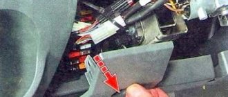
- Before starting replacement work, you need to disconnect the negative battery cable.
- Next, using a screwdriver, unscrew the screws that secure the casing and remove it.
- We look at the diagram to see where the blown fuse is located.
- We find it in the block and remove it.
- We take the same one at face value and install it in place of the extracted one.
- Attention! On the back of the block there is an electric fan fuse with a rating of 30 A, its body is painted green. The other elements are rated 15A and are blue.
- If we do not plan to change the block, then the work is finished and all we have to do is install the casing in place and secure it with screws.
- But if you decide to put the system with fuses in order and replace the old block with a new one, then we need to use an 8-mm socket to unscrew a couple of nuts that secure the block.
- Now we remove the block itself.
- Disconnect the block with wires.
- We change the block.
- We install fuses in it.
- We secure it with nuts.
- We return the casing to its place and tighten the screws.
- This completes the work with electrical fuses on the VAZ 2121 Niva.
Unscrew the screws
Removing the cover
We remove the burnt out
Unscrew the nuts
Removing the block
Diagnostic hole
Attention! If the fuse blows again, then it is necessary to look at the entire circuit, and specifically at the consumer for which this fuse element is responsible.
Never use homemade jumpers or a fuse of a different rating instead of a blown one.
This video uses the example of a VAZ six to show some reasons for replacing the block. As you can see, during operation the body was deformed and melting was noticeable.
Like the video, everything is very simple in terms of time; such work will take no more than half an hour, instead of two or three hours of standing at a service station and spending extra money.
Have you blown fuses on your car?
Survey
- Yes
- No
- First time I've heard about them
Main and additional fuse blocks
Heater fan, rear window defroster, rear wiper and washer system, windshield washer pump
Steering column switch, windshield wipers, hazard warning lights, breaker relay (in turn signal mode), reverse light, instrument cluster (coolant temperature gauge, fuel level gauge, tachometer, warning lights: turn indicators, differential lock, parking brake, emergency condition of the working brake system, insufficient oil pressure, fuel reserve, battery charge)
Left headlight (high beam), high beam indicator lamp
Right headlight (high beam)
Left headlight (low beam)
Right headlight (low beam)
Side light lamps in the left front and left rear lights, license plate lights, side light indicator lamp
Side light lamps in the right front and right rear lamps, backlight lamps for the instrument cluster, cigarette lighter, switches, heating and ventilation control unit
Hazard switch, breaker relay (in hazard mode), heated tailgate glass relay contacts
Sound signal, interior lamps, brake lamps in the rear lights
Fog light relay contacts in rear lights
| F11 (8A) | Turn signal lamps and relay-breaker for turn signals and hazard warning lights (in hazard warning mode) |
| F12 (8A) | Daytime running light relay, daytime running light bulbs |
| F13 (8A) | Rear Fog Lamps and Relays |
| F14 (16A) | Cigarette lighter |
| F15 (16A) | Spare |
| F16 (8A) | Spare |
Additional fuse circuits in the Urban package:
Fuse number and rating
Electric windows for front doors Electric side mirrors
Air conditioning fan, air conditioning compressor
Side mirror heaters
Central interior lamp
Air conditioning fan, air conditioning compressor
Dashboard
For subsequent modifications of the VAZ 2121, the instrument panel was thoroughly redesigned. In particular, the design and location of the warning lamps have changed, and new scales have appeared on the instrument panel indicators.
Original wiring diagram for VAZ 21214 – instrument panel and warning lamp harness
All control devices are interconnected. This combination consists in particular of:
- speedometer;
- tachometer;
- coolant temperature indicator;
- 12 indicator lamps;
- battery charge sensor;
- fuel level indicator.
DETAILS: VAZ 2131 Niva: price of VAZ 2131 Niva, technical characteristics of VAZ 2131 Niva, photos, reviews, video
All of them are located on the panel.
The schematic diagram shows the combinations available on the instrument panel:
- tachometer (1);
- stabilizer (2);
- panel illumination (3);
- coolant heating indicator (4);
- gasoline level (5);
- toxicity reduction systems (6);
- heated luggage door glass (7);
- fog lights (8);
- high beam (9);
- outdoor lighting (10);
- turn signals (11);
- TG level (13);
- oil pressure (14);
- differential locks (15);
- fuel reserve (16);
- seat belts (17);
- parking brake (18).
D1, D2 are diodes (type IN4002).
Cars manufactured before 1996 also have a voltmeter (12 in the diagram).
Finally, there are two resistors:
- R1 – at 470 Ohm (0.25 W);
- R2 –51 Ohm, (5 W).
Engine control system fuses
It is located on the left side of the body, under the instrument panel, next to the diagnostic block. Consists of four fuses:
| F1 (30A) | Right electric fan relay contacts |
| F2 (30A) | Left electric fan relay contacts |
| F3 (15A) | Relay windings of the right and left electric fans, controller, injectors, ignition coil |
| F4 (15A) | Heating elements for control and diagnostic oxygen concentration sensors, phase sensor, mass air flow sensor, canister purge valve |
Engine Control Relay Box
Below the main and additional fuse blocks there is a relay block for the engine management system, which consists of five relays and one fuse:
| №1 | Ignition relay |
| №2 | Main relay |
| №3 | Right cooling fan relay |
| №4 | Left cooling fan relay |
| №5 | Fuel pump relay (fuel) |
| №6 | Fuel pump fuse F5, 15A |
On some vehicle versions, a starter relay may be located under the additional unit next to the ignition relay.
Relay block diagram above the gas pedal
| №1 | Rear fog lamp relay |
| №2 | Rear window heating relay |
| №3 | Low beam relay |
| №4 | High beam relay |
Diagram for switching on the dimensions of the Niva 21213 car |
Scheme for switching on the external lighting (dimensions) of the Niva 21213 car
Elements of the diagram for switching on the dimensions of the Niva 21213 car
1. Side lamps in the front lights of the car. 2.Fuse block. 3.Outdoor lighting switch. 4. Instrument lighting switch. 5. Indicator lamp for turning on the dimensions in the instrument cluster. 6.License plate lights. 7. Side light lamps in the rear lights.
A - to the lighting lamps of the instrument cluster, switches and backlight display.
Notes and additions
More diagrams of the Niva 21213 car
— Connection diagram for low and high beam headlights Niva 21213
— Wires for the rear lights of the Niva 21213 car, diagram
— Connection diagram for generator 9412.3701 for Niva 21214
— Body clearances of the Niva 21213 car, diagram
— Connection diagram for direction indicators Niva 21213
Mounting blocks for Lada 4×4 2021
The main and additional units are located in the cabin to the left of the steering wheel, under the instrument panel. The blocks contain fuses of the “Cylinder” size, ten and six fuses, respectively. The ratings and purpose of the fuses are indicated in Table 4 “Circuits protected by fuses”:
Fuse block of standard size “Standard”. The block is located on the left side under the upholstery and contains fuses that are designed to protect engine control system devices. The ratings and purpose of the fuses are shown in Table 5:
The fuse and relay box is located on the left side of the steering column under the instrument panel. The block contains two “Standard” size fuses, which are designed to protect the circuits of the electric fuel pump, electric windows and electric mirrors. The ratings and purpose of the fuses are shown in Table 6:
The fuse and relay box is located on the right side of the steering column under the instrument panel. The block contains one “Maxi” size fuse and two “Standard” size fuses, which are designed to protect the circuits of the hydraulic unit of the anti-lock braking system. The ratings and purpose of the fuses are shown in Table 7:
Mounting blocks for Lada 4×4 2021
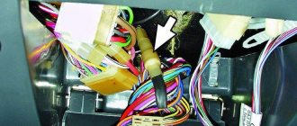
Turn signal relay
(part number 8450082700, 9-pin), as well as the windshield wiper relay, are located under the trim in the driver’s feet, to the left of the fuse mounting block. Also, the turn signal relay can be located behind the instrument cluster, or under the center console closer to the left side.
Why does a fuse or light relay or any other constantly blow out? Before replacing it with a similar one, you must first find and eliminate the cause of its burnout. This could be a short circuit, incorrectly selected rated current, etc. Use electrical circuit diagrams to troubleshoot problems. Questions on this topic can be asked on the forum.
Source
Location
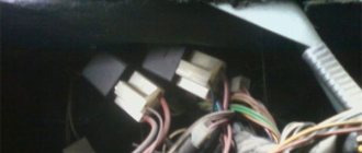
All fuses are located in a special block, which is located under the dashboard on the driver's side. In order to gain access to them, you need to remove the cover, which is secured with two screws, removing which you can see 8 electromagnetic relays and 20 protective elements. The main task of the relay is to relieve the switch contact of the device, since they consume current for which the switches are not designed.
Before installing a new element, it is necessary to understand the reason why it failed and eliminate it, otherwise they will constantly burn out. This can be done using a special tester, as well as an electrical circuit diagram. If you do not have the necessary device or do not understand the circuit, then it is better to contact a specialist.
Let's take a closer look at what each device is responsible for:
The Niva Chevrolet mounting block also has relays that are responsible for:
- K1 is usually not used and a special jumper is placed in its place
- K2 is responsible for turning on the wipers
- K3 thanks to it the emergency lights and turn signals are turned on
- K4 is responsible for turning on the low beam
- K5 provides power to the low light
- K6 relay for heated rear window, ventilation and heating system, washer
- K7 heated rear window
- K8 is a backup
There is also a separate block that controls the operation of the engine and has the following circuit:
Every driver should have a printed Chevrolet Niva fuse diagram in his car, this will make it possible to reduce the time of searching for the right device.
Niva 2121 / Lada 4×4 - fuses and relays
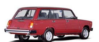
Niva SUV is known as the VAZ-2121
(VAZ 21213, VAZ 21214) and since 2006 as
Lada 4x4
.
Produced from 1977 to the present with various body modifications, mainly 3- and 5-door station wagons with gasoline engines ( carburetor, injection ). In our publication you will find a description of the fuse and relay blocks of the Niva 2121 with their locations, photo examples of execution and block diagrams. Note the fuse responsible for the cigarette lighter. In conclusion, we will offer a Niva electrical diagram for downloading.
Due to the long production period and the huge variety of designs, there is no one general description of the fuse and relay block for Niva 2121. In your car, the purpose of the fuses may differ from those presented.
All main fuse and relay boxes are located in the passenger compartment, under the instrument panel on the driver's side.
Chevrolet Niva spare parts stores in Moscow
You can select the part you are interested in for Chevrolet NIVA Chevrolet NIVA cars and order and purchase spare parts in Moscow online, as well as install them in one of our service centers according to the standards of an official dealer
Specify the make, model and VIN number of the car for a more accurate selection of spare parts or select it from the garage.
Indicate the catalog numbers of spare parts or simply write down which spare parts you need in a list, and our specialist will select the correct numbers, check prices and availability.
Pay for your order online or in our offices upon receipt. Pick it up at a car dealership convenient for you in Moscow.
Engine Control Relay Box
It is located under the main fuse box and consists of 5 relays and 1 fuse.
Scheme
Electrical diagram of the block
Decoding
The only difference between Nivas with injection and carburetor systems is due to the fact that the engine control relay unit can be located under the hood of the car in a specially designated compartment.
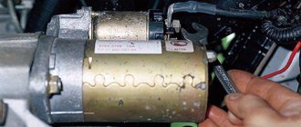
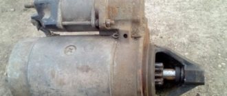
Lada 4×4 3D › Logbook › Extras. Niva starter relay
Hello friends! I wrote about my problem with starting the car earlier, the essence is simple: you turn the key, and in response there are only clicks. I didn’t know what it was, the car had this problem since it was purchased in November 2015. Since then, there have been no hypotheses, no matter what has not changed (explosive wires, starter retractor, switch), in addition, all the places where the minus is attached to the body have been cleaned. Nothing helped. We thought and wondered, consulted for a long time - what to do? I asked a question here, they gave me different advice, and so my friend and I decided to install an additional relay on the starter. Maybe it will help! And let me tell you, it helped! To solve the problem, we bought: a 4-pin 30A relay, “mothers, fathers”, 1.5 wire (taken with a reserve), heat shrink. We prepared and assembled everything according to the diagram, all that remains is installation.
Source
Additional relay block
This block is located above the gas pedal.
Scheme
Description
A little higher, above the block, a relay can be installed - a breaker for the turn signals and hazard warning lights.
Separate fuses and relays can be installed under the hood: on cars with ABS, on the left side of the engine compartment near the ABS hydraulic unit, a block with fuses is additionally installed that protect the elements of the anti-lock brake system and the starter relay not far from the starter itself.