Hello! Today I want to talk about the problem of licking the threads in the front wheel hub of the VAZ 2101 -2107, this also applies to the threads in the axle shaft. And it was like this...
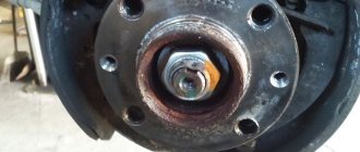
While driving, a humming noise appeared from the front right wheel. After certain tests, the cause of these sounds was identified - the hub bearings were worn out. The diagnosis is natural - the bearings and seal need to be replaced. But everything turned out to be not so simple. Upon closer inspection, it became noticeable even by eye that the hub had become a little egg-shaped, that is, oval in shape.
The wheel was difficult to remove from the hub. As we later found out, this could have happened due to jamming and excessive heating, sudden cooling occurred, as a result of which the hub began to move. I had to change that too. But another problem is where to get it in the middle of the night? And I don’t want to spend money on a new one, although this is everyone’s business.
Broken thread in the hub
As a result, a hub was found in which 3 (.) of the 4 threads in the holes were torn off. The action plan was like this:
- Take the old hub and wash it from dust and dirt.
- Drill a hole.
- Cut a thread for a bolt from a Moskvich 2141 car.
- Drill holes in the washer that fits onto the top of the brake disc.
- Take it easy!
Well, I immediately hear the cries of opponents, but within the limits of a small family budget, this is the most profitable option. And if the thread in the hub is not very good, then you can use my advice.
First of all, we bought 3 bolts from Muscovite 2141, they are thicker than the Zhiguli ones - M14, pitch 1.5. Corresponding taps, a tap holder, and a drill were also found. Taps No. 1 and No. 2 were used, the difference is in the depth of the threads on the tap, that is, the first one does not make the entire thread profile, but only outlines them, while the second one displays the full profile.
It is, of course, better to drill on a drilling machine, but you can easily get by with an electric drill and a vice in which you need to secure the hub with the broken thread. After cutting the thread, we check whether the bolt fits well. If everything is done well, the bolt should be screwed in by hand without jamming. The last step is to drill the holes in the washer.
A few photos for the article about the broken thread in the hub:
Threaded hole repair (restoring damaged threads)
Our company does not restore threads. This article is intended solely to introduce you to the thread restoration process. In our stores you can buy fittings (threaded inserts), drills, taps, thread restoration kits.
The information is intended for persons carrying out repairs in a personal garage and car repair shops. In accordance with this, the text is structured and recommendations are given. The use of this method in manufacturing enterprises involves the use of specific tools and devices, and other technology.
About the car wheel hub
Reading time: 6 minutes
Many drivers mistakenly believe that when maintaining a vehicle, it is enough to just balance the wheels and check the wheel alignment. However, the main part through which the wheel and tire rotate is the hub. It is inside this part that there is a bearing, the serviceability of which affects the rotation of the wheel, and any violation of the position of the disk or its imbalance inevitably leads to weakening and rapid wear of the hub.
Recommendations for work
Before cutting threads, you need to know certain rules for working with equipment.
If they are not followed, the turn may turn out to be bad, and the threading tool will not last long or may even be damaged during cutting. There are a number of requirements not only for the tool, but also for carrying out work of this type:
- work should always be carried out only with the help of a serviceable and fairly sharp tool;
- Before work, the iron pipe is prepared in advance - old paint, rust and dirt are removed from the cutting site. The surface is cleaned to bare metal;
- using a grinder or grinder, an external chamfer is made at the end of the pipe;
- When developing turns, it is necessary to carry out repeated lubrication of the cutters and the working surface of the pipe. For this purpose, a lubricant or a special composition is used. They are applied both before work and during the process.
Special lerks
In addition to ordinary tools, special tools can be used for cutting threads on pipes. They can be:
- metric;
- left;
- pipe;
- pipe conical.
Before cutting a thread on a pipe, you need to pay attention to the specific markings of the product.
Cutting process
So, for example, a metric tool makes turns in millimeters, and can be designated as M8, M10, etc. Accordingly, with such a tool you can cut threads on a pipe with a diameter of 8 or 10 mm.
In addition, the tenderloin is cut step by step with this tool, and each individual step corresponds to the distance between new turns.
A metric gauge can have not only the main, but also an additional turn pitch. Such thread cutting tools can be marked M 12-1.5, M 12-0.75 or M 12-0.5. The distance between the turns will decrease in proportion to the decrease in pitch.
In particular, it is worth highlighting the left-hand thread. Already from the name it is clear that the presented tool provides cutting of left-handed threads.
This variety is not as common as the usual one, but to perform them you will need a special thread-cutting tool.
Typically, a device of this type is used for cutting threads on pipe connections that will then need to rotate. This variation is distinguished by a special marking, which is designated as LN.
The pipe tool creates cylindrical threads on small tubes, studs and rods. The conical blade is irreplaceable when developing heating and water supply systems. The product is marked “K”.
Solid and sliding tray
A solid-type thread-cutting tool allows you to achieve good quality coils on a pipe. Using a one-piece tool, you can form both metric and inch threads.
Thread cutting using a solid die occurs quite quickly, and a positive result is obtained due to the high rigidity characteristics of the metal from which the tool is made.
The only significant drawback of the thread-cutting solid die is the low level of wear resistance.
Such models can be used in cases where there are no special requirements related to accuracy for the thread.
The thread-cutting tool may have little spring during operation, which will lead to insignificant changes in the diameter of the thread.
The difference can be 0.1-0.3 mm. Another drawback of a one-piece drill is its low degree of rigidity, due to which thread cutting does not always come out clean and clear.
Cutting process
The sliding type tool is equipped with special guides that greatly simplify thread cutting.
This model consists of two parts, which are attached to the frame using special screws. Screws help to regulate the characteristics of the turns cut on the pipe with the highest precision.
For more efficient work, it is recommended to acquire a whole set of dies - this will allow you to create a cut of a suitable diameter without much effort or difficulty. Before cutting the thread on the pipe, it is important to secure the sliding ladder with locking screws.
Also for this purpose, thread-cutting chucks can be used, for fastening which conical-shaped recesses and special angular-type grooves are used. The grooves are great for adjusting the accuracy of the future connection.
Types and differences
- whole;
- split;
- sliding;
- round;
- square;
- hexagonal;
- prismatic.
The thread cutting set is classified taking into account not only the shape, but also the design of the body.
Pipe thread cutting tools
The formation of round type coils is done using a tool with GOST 13536–68, cutting cylindrical threads on pipes is done with tools that comply with GOST 9740–71.
Conical notches on pipes are used with equipment made in accordance with GOST 6211–81. It is recommended to make turns using the more common round leash.
This threading tool allows you to form threads with a large pitch in metric measurement, or pipe threads with a small pitch in inch measurement.
But if the carving on the pipe requires special precision, then a round lerka will not work. This is explained by the fact that its cutting edge during manufacturing is not subjected to grinding after heat treatment.
READ How to cut threads on an Izh 250itvm machine
Cutting threads with a ruler
Another feature is the dependence of the size of the thread being cut on the external diameter of the tool. The larger the diameter of the hole in the hole, the better the removal of chips and the better the quality of the thread on the pipe.
Wheel hub device
The wheel hub is an important part in any car, the main function of which is to receive torque from the axle and transmit it to the wheel to move the car. In addition, the hub has hardware for attaching a wheel rim to it. The product is a metal blank, which includes the following elements:
Wheel hub
- The main component of the hub is its body, which is designed to install studs on it in the amount of 4, 5, 6 or 8 pieces, of different lengths and diameters, depending on the class, size and weight of a passenger car or small truck. The wheel rim is put on and fixed onto these studs, so the body of the part is made of high-strength steel and with thick walls, since it absorbs all the loads transmitted through the wheel from the road to the suspension.
- A bearing is securely hidden inside the housing, which completely reduces friction when the wheel rotates.
- Inside the bearing there is a specially machined hole on which splines are installed, and through it the elements of the CV joint axle shaft are threaded. This system is designed to receive torque from the motor and, accordingly, to set the wheels in motion.
- On modern high-class cars, with ABS, a tire pressure sensor and other useful options, all these devices are fixed on the hub and connected to the on-board computer through a system of wires and cables.
Test. Take 1
To begin with, take a stud with a diameter of 12 mm and a thread pitch of 1.25 mm. There's nothing wrong with her carving. Therefore, first, let's damage the thread - replace the threads. Let's check how serious the damage was caused. Let's try to screw a suitable nut onto the stud. We tried not in vain - the nut does not screw on. We remove it and start testing our device.
READ What do the numbers on the screwdriver in front of the chuck mean?
We clamp the damaged pin with a vice and put the required die on it. In this case, the halves of the die should be positioned so that the markings on them are on one side. We combine the threads on the stud and the die and put on the mandrel. Make sure that the two pins in the mandrel fit into the holes in the halves of the die.
Let's start spinning. In theory, we need a hexagon, but we twist it by hand with almost no effort. This is very suspicious. There is a little resistance, but not strong enough. We remove the die - it is clear that the pin was rubbing against its walls - and check whether the nut will fit. The nut is screwed on... and, having reached the damaged area, it stands up again! Conclusion: this die from the kit is not working.
The main causes of hub failure
That is why, in case of the first signs of damage, you must immediately contact the nearest service center for repairs. The main causes of part failure lie in the following factors, each of which can occur independently of each other:
- If the driver drives the car carelessly or drives at high speed on an uneven road, the studs on the hub can easily become deformed, and the bearing will crack and begin to gradually fall apart. In both cases, the car owner will feel vibration in the steering wheel and an unpleasant sound in the area of the defective wheel.
- The same thing happens when the vehicle owner rarely maintains the wheels and suspension, which causes loss of lubrication over several seasons and the bearing begins to seize, which leads to its disintegration.
- If a collapsible hub is installed on the car, and the car owner used the services of specialists to replace the bearing or carried out other routine work on the part, he needs to make sure that it is tightened with the required force and evenly. Otherwise, a distortion may occur.
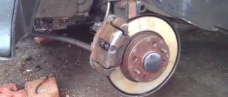
This damage will be noticeable when you press the brake pedal, since the brake discs are attached to the hub. If they deviate from the central axis, the friction material of the pads will not be able to accommodate them over the entire area, and beating will begin.
Therefore, many automobile factories prefer to supply this part assembled, since a large number of nuances during repairs can cause the entire system to malfunction, for which the manufacturer can no longer provide a guarantee.
Bearing for radial hub
- It happens that tire service technicians do not tighten the nuts properly after replacing a wheel rim or during other repairs that involve removing a wheel. In such situations, during operation, it begins to gradually become loose, which causes vibration in the steering wheel. At the same time, the hard steel begins to wear away the threads on the studs, gradually rendering them unusable, and also affecting the bearing due to the uneven distribution of masses.
- In some cases, especially in front-wheel drive cars, over the years the bearing, its seat, and the hole for the axle shaft wear out. Sooner or later, even if there are no signs of failure, these parts must be replaced every 5...7 years. Operating a car with worn elements can cause the disc to jam right on the road while driving.
Causes of internal thread wear
Damage to the thread can result from a number of reasons caused by various external irritants. They can be overload during tightening, corrosion of the material, contamination of the channels, and the most common wear. Thanks to the innovative HELICOIL plus technology, it is possible to repair damaged threads in the shortest possible time and without much effort. Threaded inserts from this brand guarantee wear resistance, high strength, and resistance to thermal stress.
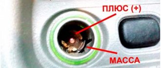
There are two “color” samples of HELICOIL plus thread inserts:
Green color is the “free running” shade. The red color is a “screwlock” shade.
The difference in color schemes makes it possible to significantly simplify the work, and then - the identification of objects after they are placed in place.
Threaded inserts from the manufacturer HELICOIL plus are widely popular in the automotive and space industries, as well as in the machine tool industry. Units in shipbuilding or aircraft manufacturing are not bypassed; in addition, they are used in electronic technologies.
Wheel hub axle VAZ 2107
The wheel hub axle for the VAZ 2107, as well as for many other models of the concern, is of particular importance for the functioning of the car.
The axle in a domestically produced car has the following functions and design features:
- The rod has a thread cut at the factory in 2 mm increments, which controls the tightening when installing and adjusting the bearings so that they are sufficiently tight, but at the same time do not interfere with the free rotation of the wheel.
- The axle also determines the maximum degree of freedom for the bearing, depending on the requirements of AvtoVAZ engineers. This data is specified in the vehicle's operating manual.
- If the rod wears out or fails, it must be replaced. Signs of such a defect will be expressed in increased play of the bearing inside the housing, which will lead to its destructuring. Of course, many experts try to sharpen it, cut new threads, and also solder an additional layer of metal, but these tricks have a short-term validity.
- If the axle on a VAZ 2107 fails, the entire suspension of the car and its bolsters are at risk. Since not only the bearing, but also shock absorbers, oil seals, ball joints and axle fork elements are subject to loads beyond their design.
- One of the main functions of the trunnion is that it acts as a plug, preventing dust, road dirt, chips from brake pads and other foreign elements from entering the bearing, which will inevitably lead to greater frictional forces, causing its overheating and deformation.
Gear repair
Wear of gears is a rather serious defect that must be eliminated immediately after detection, since further operation of the mechanism can lead to partial or complete destruction. If the teeth are worn beyond the permissible limit, the gears are replaced or repaired in the following ways:
When only one side of the teeth wears out, the spur wheel is turned over to work on the other side of the teeth. In this case, for asymmetrical wheels, the hub is cut on one side, and a bushing is attached or welded on the other.
The ring gear is cut off, a ring is made, which is pressed onto the remaining part of the wheel and locked; grind the crown and cut teeth on it.
The teeth are fused by gas or arc welding using copper templates using rods made of the appropriate material, followed by mechanical and heat treatment. For small teeth, welding is carried out in a continuous layer.
In low-impact low-speed gears, a section with a broken tooth is milled out in the wheel (rectangular or dovetail-shaped), and an insert is secured into the resulting groove with screws or welding.
To replace one of the wheels of the block, it is annealed (if necessary) and ground down, a new ring gear is made and pressed on, which is secured with screws, pins, keys or welding.
When the wheel mounting hole is worn out, it is restored by boring and pressing a repair bushing into it. Surfacing of the hole followed by boring is also possible.
When the ends of the teeth are crushed, the wheel is turned or ground from the end.
Cracks on the rim of large wheels are either welded or tightened with pads on both sides and secured with screws. If there is a crack on the hub, it is machined over a short length to press on a banding ring.
During operation of gears, wear occurs mainly along the side and end surfaces of the teeth and seats. It is also possible for teeth to break as a result of extremely heavy loads during operation.
The most common defects in the operation of gears are wear of the working tooth profile, chipping of a part of the tooth, cracks in the ring gear or gear hub, wear of the mounting hole associated with crushing of the key or splines, and dents at the ends of the teeth.
During the operation of gears, the working tooth profile is most often subject to wear. In this case, the gear wheel Moreover, if one of the gears requires replacement, then in order to maintain normal operation of the transmission, it is necessary to replace the second wheel of the pair, even if it has not been worn out.
With a one-sided load, the teeth of the gear wheel wear out only on one side, which makes it advisable when carrying out routine repairs not to replace such a wheel; it is enough to turn it so that the gear pair transmits the load with the unworn side.
READ How to Choose an Random Orbital Sander
When starting to repair gears, you should keep in mind that only those gears and racks that have a large module and large overall dimensions are restored, and the rest are replaced with new ones.
Restoring a gear by installing inserts
(when repairing non-essential low-speed gears) must be done in the following sequence:
■ mill a rectangular groove (Fig. 8.5, a) or a dovetail groove (Fig. 8.5, b) into the ring gear in place of the broken tooth (teeth);
| Rice. 8.5. Gear repair schemes: a - using an insert secured with a screw in a rectangular groove; b - welding the tooth into a dovetail groove |
■ mark the insert for installation in the groove, using the teeth of the wheel being restored as a template;
■ cut out with a chisel, saw out with a hand hacksaw (followed by filing by hand) or process the insert on a milling machine according to the markings made with an allowance of 0.2...0.5 mm for subsequent fitting in place;
■ drill a hole for a fastening screw in the cavity between the teeth of the insert (if the insert on the wheel being restored is fixed with a screw);
■ fit the insert along the groove made in the body of the wheel being restored;
■ drill a hole for the thread for the locking screw in the hub of the wheel being restored, using the hole in the insert as a guide;
■ cut the fastening thread in the hole made in the wheel hub;
■ secure the insert to the wheel being restored with a screw (Fig. 8.5, a) or weld it (Fig. 8.5, b);
■ file the insert profile first using a file according to the previously made markings;
■ check that the thickness of the insert teeth meets the requirements of the technical specifications using a caliper gauge;
■ check the main and circumferential pitch of the insert teeth using gear gauges of the main circumferential pitch;
■ check the runout of the teeth of the installed insert using a runout gauge.
Surfacing of a tooth to replace a worn one
(Fig. 8.6) must be done as follows:
■ mill a broken tooth on the ring gear of the wheel being restored to a depth exceeding the depth of the cavity between the teeth by 0.2...0.5 mm;
■ mark, using the cavity between the teeth of the wheel being restored as a template, two copper plates with a thickness equal to the width of the wheel tooth;
■ file the copper plates so that their profile is smaller than the profile between the cavities of the wheel teeth by 0.2...0.5 mm per side, which is necessary for subsequent fitting of the welded tooth to the profile;
■ prepare fastening strips for connecting copper plates by drilling holes in them for fastening screws;
■ drill holes in copper plates for mounting screws, using fastening strips with holes drilled in them as a conductor, and cut threads into them. When drilling holes for mounting screws, copper plates are installed on the rim of the wheel being restored so that their side surfaces fit tightly to the side surfaces of the teeth, the plates are fixed in this position, and then holes are drilled using the connecting plates as a jig. Simultaneously with drilling holes in the copper plates, holes are drilled for mounting screws in the wheel housing;
■ fasten the copper plates to the wheel being restored with fastening strips and screws;
■ perform metal surfacing by selecting an electrode from the appropriate metal from the reference tables;
■ remove copper plates from the restored wheel;
■ file the end surfaces of the deposited tooth flush with the end surface of the wheel;
■ mark the surface of the deposited tooth using a template corresponding to the end surface of the tooth of the wheel being restored;
■ file the deposited tooth along the marked contour;
■ check the restored wheel.
Restoration of gears worn along the tooth profile
, must be carried out in compliance with the following technological route (Fig. 8.7):
| Rice. 8.7. Technological route for restoring a gear: a - cutting off the worn ring gear; b - turning the blank of a new ring gear; c — installation of a new ring gear on the hub; g - not cutting teeth |
■ grind off the gear ring, ensuring that a seat is obtained for installing a new ring (processing is carried out on a mandrel fixed in the centers of the lathe);
■ grind a blank for a new ring gear, first processing its outer diameter, and then, using this surface as a base, machine the mounting hole in the ring gear on a lathe;
■ press the ring gear blank onto the gear hub, check it for radial and axial runout and fix the position of the ring on the hub with mounting screws;
Did you strip the threads in the hub? then this is the place for you
■ process the teeth of the ring gear on a vertical milling machine with a modular end mill or on a horizontal milling machine with a disk modular cutter (in both cases, a universal dividing head is used).
Restoration of gear blocks
carried out by replacing one or two gears of the block, connecting them to the hub with mounting screws or on a key. When connecting with mounting screws, proceed as follows:
■ grind the hub of the worn gear block to fit the fitting size of the new gears;
■ install new gears of the block on the hub machined to fit the landing size;
■ simultaneously drill holes for mounting screws in the new gears and the ring gear remaining on the hub;
■ cut threads in the hub holes for mounting bolts;
■ fasten new gears to the hub with fastening bolts (Fig. 8.8, a);
■ check the quality of the assembled gear block for runout.
When connecting with a key, you must perform the following steps:
a retaining ring into a pre-machined groove in the hub (Fig. 8.8, 6);
a lock nut on a thread pre-cut on the hub (Fig. 8.8, c);
a locking screw into a threaded hole (Fig. 8.8, d), previously prepared in the hub and new gear of the block (the axis of the hole must coincide with the generatrices of the hub and gear seats).
Restoration of the gear sector
is produced by attaching a new ring gear to it, which is cut from a pre-cut gear wheel of the corresponding module (Fig. 8.9).
Restoration of gear racks
, as well as gears, is carried out by installing an insert or surfacing a tooth.
Restoration of gear wheels with toothed rims made of polyamide materials
(Fig. 8.10) is carried out by replacing the worn crown with a new one, for the manufacture of which a mold for injection molding plastics is used.
a - cylindrical monolithic; b - cylindrical with a steel hub; c - reinforced; 1 - cover; 2 - mandrel; 3 - annular cavity for pouring gypsum; 4 — clip; 5 - master model; 6 - base; 7 — steel hub
To do this you need to do the following:
■ grind the hub 7 of the gear wheel by removing the polyamide ring gear;
■ install mandrel 2 at the base of the mold;
■ install the reference gear (master model) 5 on the mandrel;
■ fill the annular cavity 3 with gypsum solution;
■ install hub 7 of the wheel being restored on mandrel 2 of the mold;
■ close the mold with lid 1 and secure it to the holder with 4 screws (not shown in the figure);
■ place the mold into the casting machine;
■ disassemble the mold and remove the restored gear.
Worm wheel restoration
, which in most cases are made with an overhead ring gear, is made by replacing the worn ring gear with a new one.
After restoration and assembly, gears must meet the following requirements:
:
■ the working profile of the teeth should not have holes, cracks, scratches or other visible defects;
■ the ends of the teeth of the movable gear wheels that engage and provide a change in the rotation speed of the mechanism must be rounded on the side where they engage with other gear wheels;
■ deviation from parallelism and misalignment of axes should not exceed the values indicated in the technical specifications or reference tables;
■ Radial runout must also meet the requirements given in the technical documentation or reference tables.
Date added: 2015-11-26; | Copyright infringement
Types of hubs and features of their attachment to the wheel
According to the method of attachment to the wheel, axle shaft, as well as the trajectory of the load and, accordingly, the transfer of load to the suspension, they are divided into the following categories:
- Radial, classic, when the element can only perceive torque.
- Thrust, when a locking nut is placed on the bearing, which prevents the free movement of the product.
- Radial-thrust and thrust-radial hubs are combined action hubs, most often installed on modern cars from foreign manufacturers.
The stud itself, in turn, is attached to the flange, along with the brake disc, and it is already mated through a movable connection with a bearing installed in the body of the hub. If older car models have drum brakes, they are also attached to a flange that is driven as the wheels rotate.
The hub is one of the most important parts in the chassis of a car, without which its operation would be impossible. That is why car enthusiasts need to order its diagnostics on each wheel during vehicle maintenance.
This is due to the fact that early detection of a defect will help prevent serious consequences associated with expensive repairs and save the driver from unnecessary expenses. In addition, even if the product is in order, then during a banal oil change in the engine, these parts also need to be lubricated regularly, increasing their service life.
How to restore a thread with a tap while maintaining its diameter and location
If you need to restore the thread while maintaining its diameter, use one of the following methods.
Welding the hole and then cutting a new thread
This method is rarely used due to the fact that the strength of the new thread obtained using this technology will be lower. This method is also chosen in the absence of special devices (screws and spiral inserts).
This method of thread restoration includes the following steps.
Removing old threads by drilling.
Welding the hole. The choice of technologies depends on the materials of the parts.
To weld holes in steel products, electric arc or gas welding is used in protective environments.
When working with cast iron parts, gas or electric arc welding is used in a cold state or with general/local heating.
Electrodes (MNCh-1, OZCh-1, TsCh-1), cast iron rods with a high silicon content and other materials are used as additives.
Machining the hole flush with the base metal.
Cutting a new thread.
Note! When working with aluminum products, this method of thread restoration is usually not used. This is due to the fact that the metal actively absorbs gases during welding. Pores form in the deposited layers. With severe shrinkage, cracks appear.
Restoring threads using a screwdriver
Screwdrivers are special cylindrical devices that have threads of the required diameter and pitch on the inside and large threads on the outside. Such products are made from steel, brass, bronze, copper and other materials. At the final stages of production, the screws are hardened and further strengthened.
Photo No. 2: screwdriver for thread restoration
If you need to restore the thread while maintaining the diameter using a screwdriver, proceed as follows.
Drill out the hole. The drill must be selected in such a way that the diameter of the resulting hole allows cutting a thread for screwing in the screw.
Cut the thread with a tap. Follow the rules listed above.
Screw in the screwdriver. It needs to be installed flush. If this is not possible, mill the part and remove the protruding part of the fixture.
At the border of the new thread and the screw, apply notches using a core. This will prevent the device from unscrewing spontaneously.
Repairing threads using a spiral insert
Spiral (also called wire and spring) inserts are also often used to restore damaged threads.
Photo No. 3: spiral inserts for thread restoration
These devices have high-precision rhombic threaded profiles on the inside. Almost all models are equipped with special driving tongues designed for screwing in devices.
For the manufacture of such products, especially durable high-quality stainless steel is used. This guarantees the resistance of the restored thread to deformation and corrosion.
Restoring threads using a spiral insert includes 4 stages.
Drilling. Drill out the hole. Select the diameter of the cutting tool according to the table that manufacturers provide with spiral inserts.
Image #1: Drilling the hole for the spiral insert
Thread formation. Note! To cut threads, use special taps that differ from standard ones and come with spiral inserts. Follow all rules and recommendations.
Image #2: Forming a thread for a spiral insert
Installation of the device. Place the spiral insert onto the supplied special tool and screw it into the hole.
Image #3: screwing the spiral insert into the hole
Removing the drive tongue. You can get rid of it using a special tool (manufacturers also supply it). To remove tabs from large-diameter inserts, ordinary pliers are suitable.
Using professional spiral thread inserts has the following advantages.
The required tension is ensured at the insert landing site. This completely prevents twisting. The devices are located in the receiving threads with virtually no gaps. There is no need to use glue for additional fixation of products.
Due to the elasticity of the inserts, loads and stresses are distributed evenly. This creates ideal conditions for the transfer of forces between the bolts and the receiving threads.
Spiral inserts are universal. They are used not only to restore threads, but also when it is necessary to strengthen connections. Spiral inserts are used when working with products made of low-medium and high-strength metals, as well as plastic and wood.
The thread in the wheel hub is broken, what should I do?
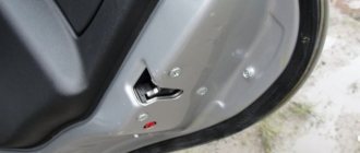
The thread was torn off, apparently on the hub. Who can answer me, whaaaaaaaaaaaaaaaaaaaaaaaaaaaaaaaaaaaaaaaaaaaaaaaaaaaaaaaaaaaaaaaaaaaaaaaaaaaaaaaaaaaaaaaaaaaaaaaaaaaaaaaaaaaaaaaaaaaaaaaaaaaaaaaaaaaaaaaaaaaaaaaaaaaaaaaaaaaaaaaaaaaaaaaaaaaaaaaaaaaaaaaaaaaaaaaaaaaaaaaaaaaaaaaaaaally she breaks down? I don’t tighten the bolts 100%; they cost 4x98 for the same hub. There was a similar problem before installing the Melbers, but short bolts were the culprit. Now the bolts are extended, everything was fine until I took off the wheel today. I put it back on, tighten it, and 2 of the 4 bolts break off, and it’s obvious that I didn’t tighten the bolts much. Maybe someone had something similar? I don't understand what's wrong. Change the hub and bearing, and how long will it take again? Use studs instead of bolts? We need to come up with some kind of solution so that they don’t just break down like that.
The photo shows that apparently the bolt was trying to cut a thread...
Repairing the threads in the wheel hub was necessary because the car owner at a service station, when changing wheels, tore off the threads on the hub for the wheel mounting bolt. How now to restore the threads in the hub?
Changing a hub due to a broken thread is expensive. We began to look for a more acceptable solution - restoring the threads on the hub. This is the situation that brought the car owner to our thread repair workshop.
When inspecting the wheel hub, it was discovered that the bolt thread in one hole had been torn off. In the place where the thread on the hub was broken, the bolt rotated freely.
Restoring wheel hub threads
We restore the broken thread in the wheel hub to the standard tightening torque. A spring insert allows the bolt to remain the same size, and our premium specialty tool ensures hole alignment. This means that when the wheel is tightened, the bolt will spin smoothly without distortion.
Thread restoration method
Damaged threads can be completely restored using the following technology:
1. Drill the threaded hole to the diameter indicated in the table below 2. special profile thread in it Screw a spiral repair insert (a durable stainless steel sleeve) into the resulting thread using a special tool.
Threaded insert
After such an operation, the thread becomes stronger than the original one in good condition. This effect is especially noticeable when the carving is made in a soft material such as aluminum. When a bolt (stud) breaks off in a threaded insert, there is no “biting” effect. A broken bolt (stud) can be easily removed.
Watch a video of how the threaded insert is used
What capabilities do threaded inserts have?
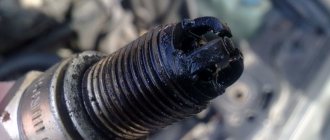
This method is especially relevant for restoring threaded holes in body parts of automobile engines, for example, a spark plug hole. The candle thread becomes very durable and reliable.
Threaded insert is screwed in Threaded insert is screwed in
If the thread for a stud is broken, sometimes they drill it out and cut the thread to the next size. In this case, you have to use a stepped stud of unknown origin and dubious quality. And not every stepped hairpin can be found at the right time. If you repair the hole using a threaded insert, you still have the option of using a standard, branded pin.
Another application for repair threaded inserts is in brass exhaust manifold nuts. The result is a nut that combines a very strong thread and the property of not “sticking” to the studs.
Owners of some foreign cars should pay attention to the possibility of replacing the M12 x 1.5 thread with an M12 x 1.25 thread. It often happens that a bolt with such a thread is damaged, and it is almost impossible to find it in a retail chain in your city (we have such bolts in our store). A turner will not turn out a decent bolt, because... The threads on factory bolts are formed by pressure (knurling), which provides the necessary strength. And on a lathe, the thread is made with a cutter, while the fibers of the steel bar are cut and the threads cannot bear the required load.
If you replace the thread in the body part with the more common in Russia M12 x 1.25, it becomes possible to select a bolt of the required size and strength from the assortment of Russian and European manufacturers of automotive fasteners presented in our catalog.
Video - how a threaded insert works, demonstration
What tools are used to restore threads?
| No. | Repairable thread sizes | Drill diameter |
| 1 | M5 x 0.8 | 5,2 |
| 2 | M6 x 1 | 6,3 |
| 3 | M8 x 1 | 8,3 |
| 4 | M8 x 1.25 | 8,4 |
| 5 | M10 x 1 | 10,25 |
| 6 | M10 x 1.25 | 10,4 |
| 7 | M10 x 1.5 | 10,5 |
| 8 | M12 x 1.25 | 12,25 |
| 9 | M12 x 1.5 | 12,5 |
| 10 | M12 x 1.75 | 12,5 |
| 11 | M14 x 2 | 14,5 |
| 12 | M14 x 1.5 | 14,5 |
| 13 | M14 x 1.25 (for a candle) | 14,25 |
To repair the spark plug hole, a stepped tap is recommended. It is centered in the old hole with its lead-in part, and immediately cuts a new thread, bypassing the drilling operation.
A stepped tap significantly reduces the risk of damage to the spark plug hole, but it is noticeably more expensive than a regular tap.
To lengthen the tap when repairing a deeply recessed spark plug hole, you can use a regular 10-point twelve-sided socket with the appropriate tool.
3.
Spindle (tool for screwing in the insert)
The working part of the spindle is similar to the threaded part of a bolt, with a hook at the end.
4.
Repair insert
Rules for cutting pipe threads using a jig
At the moment, a lecher is understood as a tool with which you can easily make turns on a water pipe or other types of similar products.
Thread cutting tool
A thread-cutting tool for creating turns is presented in the form of a nut made of strong metal, in the hole of which there are cutting teeth and edges. How to cut threads correctly with its help – we’ll figure it out below.
Operating procedure
The lathe allows you to quickly and quite efficiently form turns on any type of pipe. In order to do this, you need to know how to cut a thread correctly:
- The pipe should be firmly clamped using a vice or other device.
- The external chamfer must be removed from the already prepared and cleaned pipe.
- Insert a hole with a pre-determined diameter into the holder.
- Carefully lubricate the pipe and threading tool with lubricant.
- The lantern is attached to the pipe in this way so that its position is perpendicular to the axis of the product. If the thread-cutting tool is installed even with a slight misalignment, then the threads may break or the value of its diameter may change.
- The tool holder must be turned clockwise. This will ensure that the right cut is created on the product.
- After producing 3-5 turns, the device is untwisted in the opposite direction, during the process iron filings will be removed.
- You need to twist the tool very smoothly, and without making sudden jerks.
- It is important to keep in mind the repeated lubrication of the cutters and the internal surface of the joint with lubricant.
- After the last turn is created, the lerka returns to the top, and later goes through the completed turns again.
Please note that the connection length should not be more than 10 mm. This distance is standard for the vast majority of residential piping systems.