Porting - competent cylinder head tuning
Tuning is a popular trend among millions of car enthusiasts. Those who are dissatisfied with production cars, who seek to increase their power, resort to various types of tuning. In the matter of engine modification, tuning the cylinder head (hereinafter referred to as the cylinder head) is far from the last, but rather one of the first places, since many power indicators depend on it. Proper modification of the cylinder head allows you to achieve a significant increase in power - up to 20 horsepower, and in some cases even more. And one of the ways to increase engine power is to port the cylinder head. We will find out what this is right now.
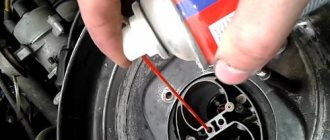
Marking the cut part on the manifold and cylinder head using a gasket.
Attach the gasket to the manifold. Anything between the edge of the hole on the gasket and the edge of the hole on the manifold needs to be ground off. You should mark this part and constantly apply a gasket so as not to remove excess. This is the most important thing - do not oversharpen.
What is porting?
Cylinder head porting is often called channel porting, since the work is specifically related to the modification of the inlet and outlet channels of the cylinder head. Exhaust gases move through the channels at a very high speed and any resistance that impedes this movement significantly affects the dynamics and power performance of the engine. Therefore, those who strive to squeeze the maximum horsepower out of the engine pay their attention even to such little things. At the same time, porting involves a colossal amount of work, and therefore costs, so let’s figure out how complicated this matter is.
Docking the collectors with the head
The need to adjust the internal surfaces of the intake and exhaust manifolds to similar channels of the block head is due to their inaccurate manufacturing and lack of adjustment during the assembly process at the manufacturer. However, a smooth transition from the manifold to the head bores is very important for good engine filling. If all the ledges are removed, the flow of the fuel-air mixture will encounter fewer obstacles on its path and a larger amount of the mixture will enter the engine cylinders.
Adjacent surface of the intake manifold
The adjacent surfaces of the intake manifold and the cylinder head must be carefully processed until a complete fit is achieved.
To begin with, it is advisable to place the manifold on pins to firmly fix the manifold relative to the block head. Next, mark the places of inconsistencies with a “marker” (alternatively, coat the surfaces with paint, separate them after drying, when broken, the places of metal protrusions on both surfaces will be visible) To prevent the marks from being erased, scratch along the contour with an awl, then treat the surfaces with cutters until a complete joint is obtained. 2 Method. Use plasticine
1. Apply plasticine to the docking area and partially inside the cylinder head channels. 2. Sprinkle with fine shavings, dust, etc. A separating material is needed to prevent the surfaces from sticking together when joining. 3. Attach the manifold to the cylinder head and tighten with bolts until the plasticine is not completely squeezed out of the crack. There should be 0.5-1mm left 4. Disconnect the manifold and the prints will show where the cylinder head material protrudes. 5. Draw a line with an awl and cut off the excess with cutters. 6. Repeat the procedure for the manifold, since the first 5 points determine the protrusion zone of the cylinder head only.
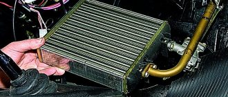
Operations to identify processing sites (metal removal), block heads for better docking with collectors.
3 Method. Use the manifold gasket. The gasket must be applied alternately to the mating surface of the cylinder head and manifold. When marking the places where metal will be removed, pay special attention to the accuracy of the alignment of the fastening holes or pins, since they are landmarks.
I’ll deviate a little from the topic and note that it would not be superfluous to dock and smooth out all the sharp ledges of all the parts located at the inlet, since they create very significant resistance to the flow of the air-fuel mixture.
Parts that create intake resistance for injection or carburetor systems:
— Steps connecting the throttle to the intake manifold and the intake manifold — Imperfect shape of the throttle valve — Imperfect shape of the mass air flow meter — Imperfect shape of the intake manifold — Corrugated intake manifold — Air filter — Carburetor junction with the intake manifold and thermal insulating insert
Exhaust manifold contact surface
If the exhaust manifold has the same internal diameters of the pipes as those on the cylinder head, then they also need to be joined. if the holes in the exhaust manifold pipes are significantly larger than the holes in the cylinder head, then there is no need to bore the head, because this measure was made specifically to limit the back pressure from the exhaust system back into the cylinders. (the exhaust gases experience significant resistance when meeting the step formed by the smaller hole on the cylinder head.)
What does cylinder head porting include?
We mentioned that porting is a modification of the cylinder head channels, and if we speak in even more detail, it is an increase in the diameter of the channels, internal processing, changing their geometry to ensure the most free movement of gases. Consequently, if the cylinder head channels have undergone changes, then new valves are needed. Those who perform cylinder head tuning prefer lightweight, T-shaped valves as an improved option. Since everything follows a chain, porting also includes modification of the valve seats, eliminating the slightest inaccuracies that can create resistance to the free movement of gases. Finally, the final stage is the modification of the combustion chamber. Refinement of the cylinder head, or porting, is a very painstaking task and requires a lot of knowledge and preliminary calculations. There are known situations when, after modification of the engine head, the engine became sluggish, and all the dynamics were felt only at high speeds. Therefore, this task should be entrusted to proven, specially trained craftsmen, since there is a high risk of not only not increasing the power, but, on the contrary, significantly reducing it as a result of a gross violation of the original characteristics.
Some historical facts
In the early 80s, the Brabham team competing in Formula 2 began using the Honda V6 engine. This motor has peak power, a weak midrange and a narrow operating range. That year, they lost outright to the 4-cylinder BMW engines. After a disastrous season, the team's engineers took a look at the engine and noticed that the intake port on the engine was too large. By simply turning it down, they immediately saw a 5% increase in maximum power (at high rpm) and a 20% improvement in mid-rpm. Porsche, for example, first built their racing engine for the 3.6 liter 911 GT3-RSR using 42 mm intake and 36 mm exhaust valves, this solution showed the best compromise for modern, small combustion chambers with 4 valves per cylinder and not large (relatively ) raising camshafts for racing engines. Subsequently, after further research and testing in 2004, they reduced the intake valve size by 1 mm (41 mm) and the exhaust valve by 2 mm (34 mm) and as a result obtained a significant improvement in engine performance. The cylinder head of each engine has its own characteristics; they are measured in air flow (flow -cfm cubic feet per minute) on special purge stands. Here is another interesting example of the Subaru WRX STI 2000cc. Indicators at the inlet to the cylinder head stock are 284 CFM (28H2O), this is a very good result. I propose to look at the characteristics of the cylinder head of the legendary Subaru WRC. At the intake duct – 265 CFM, this is quite a bit more than a stock Ford Focus (Duratek 2.0 liter) and an order of magnitude less than a stock Subaru STI 2.0. Of course, on the exhaust channel of the WRC engine, for early spool the flo was increased significantly (CFM - 218) in comparison with the stock (CFM - 174). Well, this is a different story, the stock output on the STI is far from optimal (it’s better not to compare it with a Ford turbo engine or, especially, a Mitsubishi EVO). Another example, the Duratec 2.0 engine has 255 CFM at the inlet - this is enough to produce 240 forces, why touch the head? If you want more, say 280 forces, then the standard valve size will be enough, but there are also subtleties in working with the channels; in no case should you increase their entire size (you will only spoil the performance of the motor), all effort must be directed to working with channel throat, valve and seat. If it is 300 horsepower, then it is necessary to increase the size of the intake valve by 1mm and the exhaust valve by 2mm. Any increase in the flow area of the channel will increase the air permeability (CFM indicators) and of course the maximum power, but in turn will reduce the flow speed, and therefore the compaction process (INTAKE RAMMING) will be worsened, as a result, loss of power at low and medium speeds. channels, you will not improve the efficiency of filling the cylinders, but will only shift them to higher speeds (losing the low end). The question here is whether it is better to install camshafts with large phases or to stay at the stock and open the channel (channel throat). Yes, of course, these procedures will pleasantly surprise you at high speeds, even very high. For everything to be correct, you must know exactly what you want to get. What characteristics of the engine, what maximum power, at what speeds. Miracles don’t happen if on a 2.0-liter Duratek engine the target is 280 horsepower or 1.6 fret - 220 horsepower, then of course it will not be at 7000 rpm, but somewhere at 8200-8500, and here the entire engine must be prepared (not a cheap procedure). Having set a goal, in this case you make the cylinder head specifically for this task , you need to get not more, but a specific CFM value sufficient for the task at hand (no more). All efforts must be directed toward increasing the flow, not by expanding the channel, but on optimizing the flow. Let's just say that theoretically the maximum value that can be is 146 CFM per 1 square inch (the minimum flow area, often the throat of the channel). In reality, the record holders (as of 2008) are 133 CFM/in2 for a cylinder head with 1 intake valve and 137 CFM/In2 with 2 intake valves per cylinder. Be realistic, let's say for DOHC 130-132 CFM/In2 this is a completely achievable result. The Duratek stock has a reading of 123 CFM/In2 (very cool). One of the rules for working with channels is that shape is very important, but polishing is not. A cylinder head with a rough finish, but with correctly made shapes, will always produce more power (by an order of magnitude) than a highly polished, but with incorrectly shaped bore. In general, be careful with finishing, especially the intake channel, do not use a tool for this with a grit greater than 80, otherwise the mixture formation will be impaired. In aerodynamics there is such a concept as the Boundary layer - a rough surface, unlike a mirror one, in this case this is only a plus. Polishing the exhaust channel is done in the same way as the intake channel, only in this case a little more “mirror” is needed. Exhaust gases contain carbon (carbon), it is in the form of soot, carbon deposits settle on the walls, so using an abrasive with a grain size of 240 or even 320 is welcome, this will help solve this problem. (but not more). It seems to me that it is also worth noting one of the important points that when porting the exhaust channel leads to deterioration. Very often I have seen that people try to adjust the size of the exhaust channel to the size of the exhaust runner (manifold). This operation leads to loss of power, especially at medium speeds. This may seem silly to many, but there must be a sharp jump (step) between the exhaust port and the entrance to the exhaust runner (exhaust manifold). This will help reduce the flow of exhaust gases back into the cylinders (for example, during overlap). Backflow of exhaust gases is always a problem at low speeds and, unfortunately, when installing camshafts with a larger total phase (duration), the situation only worsens. How much power you gain from a mismatch between the exhaust port and exhaust runner sizes will depend on how large the difference is, the step. But this does not mean that you should specifically choke the engine on the exhaust channel; it should be of optimal size, more precisely volume and minimum flow area. Or, conversely, use a larger diameter exhaust runner than necessary. Just make this threshold, step, do not increase the size of the exhaust port to fit the size of the exhaust manifold. For example, on a 1.6-liter racing engine, such a step can add up to 3% of maximum power and about 5% in the middle range.