- What is the purpose of the part
- How to check a diode bridge?
- In what cases is it necessary to replace a part?
- Checking and replacing the generator bridge
- Do-it-yourself replacement of the VAZ 2114 rectifier
- Useful video
A component such as the VAZ 2114 diode bridge is a key part of a car generator. You need to understand that if such a part fails, the generator will not be able to work. Also, if the electronic system breaks down, there are risks. Experts advise regularly checking the condition of the part.
How to install a diode bridge (rectifier unit)?
The diode bridge is installed in strictly reverse order.
How to replace a diode bridge without errors. Useful advice from an auto electrician.
Background:
My 140 amp generator started howling in an inhuman voice a long time ago, I removed it and sent it for diagnostics. The diode bridge was ordered to be replaced. As a result, the generator was put aside in the nightstand. My old 80-amp generator recently broke down, and I also took the battery with me... In general, I decided to repair the diode bridge on my own, since a new one costs more than 10 thousand rubles, and the auto electrician did not know where can he buy 50 amp diodes?
You can’t find diodes in Automotive stores; they are rated at a maximum of 30-35 amps, but my task was to find diodes rated at 50 amps. As a result, after surfing the CARGO online catalog, I found the ones I needed. I'm publishing the numbers.
Diode Cargo 50A - 138634 - 6 pcs. Diode Cargo 50A - 138635 - 6 pcs.
For a 140 ampere generator you need 12 diodes - 6+6, for an 80 ampere generator only 6 - 3+3.
We also need a tool, a soldering iron of at least 50 watts with all the accessories. Paint. I chose heat-resistant silicone. I applied it with a brush, so the layer is thicker. Well, my hands don’t smell too much))
Main stages:
— We dismantle the diode bridge — We remove the old diodes — We halve the diode bridge — We install the diodes (carefully hammer them into the case through a wooden spacer) — We assemble the bridge, solder the contacts — We paint carefully in several layers — We put the bridge in place
On one half of the bridge there are diodes of one type, on the other half - of a different type (different polarity). Having the most ordinary multimeter it will not be difficult to understand where each one is located.
Signs of a malfunction of the diode bridge of the VAZ 2110 generator
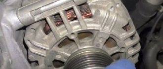
Removing the diode bridge of the generator
Frequent repairs of the rectifier unit are inevitable during extreme use of an SUV - crossing rivers, “mud baths” of the car while fishing and hunting. Therefore, this category of car owners solves the problem radically by moving the rectifier along with the voltage regulator relay to a separate unit, higher under the hood.
For example, the bottom photo shows a diode bridge of a car generator inside the air filter housing.
Rice. 14 Remote diode bridge in the filter housing
The main nuances of tuning in this case are:
- the filter housing protects the electronics from moisture;
- the cooling problem is completely solved;
- the maintainability of the unit is increased, there is no need to disassemble the generator;
- the terminals are reinforced, a larger cross-section wire is used;
- the heat-shrinkable material was not subjected to high-temperature treatment, so the bundle inside it remained soft;
- A bridge with 8 90 A diodes was used.
If necessary, the remote unit can be mounted inside the cabin, for example, behind the passenger seat.
What generator malfunctions can a car owner encounter?
- The pulley is worn out or damaged;
- Current collecting brushes wear out;
- The collector wears out;
- The voltage regulator is damaged;
- The bearing is worn out or damaged;
- The rectifier (diode bridge) is damaged;
- The charging circuit wiring is damaged.
List of the most common battery faults:
- The occurrence of short ignition of electrodes or plates;
- The battery plates are mechanically or chemically damaged;
- The geometry of the battery cells is disrupted - cracks appear on the housing due to mechanical damage or incorrect installation.
- The battery terminals are oxidized.
These malfunctions arise due to gross violations of operating rules, as well as manufacturing defects and expiration of service life. The number of generator set malfunctions is much greater, since the design of the generator is more complex than that of the battery. In order to avoid being deceived in the service if any malfunction of electrical equipment occurs, every car owner should know about the main causes of generator malfunction and a possible way to eliminate it.
To prevent unexpected breakdowns, it is necessary to carry out quarterly inspection of the vehicle's electrical systems.
There are two types of generators: AC and DC. In a modern passenger vehicle there is a generator operating as alternating current, into which a rectifier is built in. The consequences of a burned out diode bridge can be disastrous. It converts alternating current into direct current, which is necessary for the operation of electrical consumers of the car. The surface of the cover and housing of the generator set is where the diode bridge is located.
- How to increase onboard voltage - very simple
The amount of operating current depends on the voltage required for the operation of all electrical consumers of the car. The operating voltage value is usually in the range from 13.8 to 14.7 V. The operation of the generator set directly depends on the crankshaft speed, since the drive element is the belt. The relay regulator smoothes and regulates the current at the output of the generator. It stabilizes and prevents surges and dips in operating voltage. Modern generators have built-in integrated voltage regulators, popularly called “Tablets”.
How to check the generator diode bridge correctly and yourself. Autoelectronics
How to check a diode bridge with a multimeter How to check a diode bridge
Removing the diode bridge of the generator
Frequent repairs of the rectifier unit are inevitable during extreme use of an SUV - crossing rivers, “mud baths” of the car while fishing and hunting. Therefore, this category of car owners solves the problem radically by moving the rectifier along with the voltage regulator relay to a separate unit, higher under the hood.
For example, the bottom photo shows a diode bridge of a car generator inside the air filter housing.
The main nuances of tuning in this case are:
- the filter housing protects the electronics from moisture;
- the cooling problem is completely solved;
- the maintainability of the unit is increased, there is no need to disassemble the generator;
- the terminals are reinforced, a larger cross-section wire is used;
- the heat-shrinkable material was not subjected to high-temperature treatment, so the bundle inside it remained soft;
- A bridge with 8 90 A diodes was used.
If necessary, the remote unit can be mounted inside the cabin, for example, behind the passenger seat.
How to check a generator rotor with a multimeter
A faulty car alternator rotor primarily causes the charging current to disappear and the battery to discharge. This is indicated by the low battery light located on the instrument panel. The position of the voltmeter needle is near the red zone or in the zone itself. In this regard, it becomes necessary to check the generator armature with a multimeter.
When checking the voltage with a multimeter while the engine is running, its readings at the battery terminals will be less than the required 13.6 volts. In order to obtain more accurate results, it is recommended to check the battery charging from the generator in advance with a multimeter.
The main rotor malfunctions are considered to be a short circuit of the windings and a break in the leads between the field winding and the slip rings. To check, it is not necessary to remove the generator from the engine and remove the rotor from it. It is enough to remove the voltage regulator relay and perform all the necessary actions through the resulting window.
In order to check for a short to ground in the rotor field windings, you need to set the multimeter to mode and press the positive probe one by one against the slip rings. The negative probe is pressed against the mass - the generator housing. If the resistance indicator tends to infinity, then the rotor is working properly and there is no short circuit to ground. After this, you should check the generator winding with a multimeter for an open circuit. The multimeter is also set to ohmmeter mode, the positive probe is applied to one contact ring, and the negative probe to the other. A resistance value of 5 to 10 ohms indicates the serviceability of the excitation winding. In most cases, a faulty rotor must be replaced.
However, not all elements can be verified through testing. For example, it is not possible to check the generator brushes with a multimeter. This procedure involves visual diagnostics after the brush apparatus is removed. If necessary, the voltage regulator can also be removed. As a rule, brushes show uniform wear. In normal condition, the length of the brushes is 8-10 mm. If this indicator is less than 4.5 mm, then the brushes must be replaced. At the same time, carbon dust formed as a result of friction of the brushes on the rotor rings is cleaned out.
When diagnosing a generator, rotor failure is the last thing to be considered. First of all, other elements are checked that are more likely to cause malfunctions of the device. Low voltage, a burning light on the instrument panel and other symptoms can occur if the diode bridge or relay regulator fails. First they are checked, and only then the rotor itself.
Reversed and tunnel type
Here, the principle of analyzing the dependence of the current on the magnitude of the voltage applied over a specific time interval is applied. As in other cases, you will need to assemble a circuit of a certain type.
List of elements:
Checking the functionality of the generator on VAZ cars
V.D.
– tunnel modification diode under test;
Up
– galvanic unit for supplying power to the system;
Resistances: R1, R2, R3 – 600Ω.
The measurements are within certain limits - not less than the maximum current of the part being tested. The marking contains information to familiarize yourself with the necessary parameters.
The process algorithm itself consists of setting the maximum on R3, a variable resistor. Then, following the correct connection order, the part is attached, and observations are made with a smooth, rhythmic decrease in the value of R3.
Diagnostic methods
As practice shows, diode bridges periodically fail on any vehicle, regardless of make and model
It is also not fundamentally important whether you use diode bridges from Valeo, Bosch or any other manufacturer
Most often, one or several diodes burn out in a DM. As for the reasons, here we can highlight:
- dust ingress;
- negative impact of dirt;
- contact of diodes with oil;
- accumulation of moisture in the generator;
- polarity error when lighting;
- incorrect battery connection;
- overload in the electrical network;
- errors in the installation of electrical equipment;
- factory defects, etc.
If you set a goal, the bridge can be checked in normal garage conditions. For such tasks, use a light bulb or a multimeter.
Before starting work, remove the protective casing from the DM, and also do not forget to disconnect the terminals on the regulator. Remember that all bridges are positive, that is, positive diodes are equipped with red wires, and negative ones are black. Don't get confused.
Now in more detail about each of the methods.
Multimeter
If you decide to use a multimeter to check the bridge, you will need to perform several sequential procedures.
The whole process looks like this:
- the bridge is dismantled from the generator (no other way);
- each diode will need to be checked separately;
- the beeper mode is selected on the measuring device;
- This setting will allow you to hear a signal when the probe is shorted;
- if this mode is not available, select the 1kOhm position;
- the probes are brought to the edges of the diode;
- a measurement is made;
- the probes are swapped.
Now regarding the measurement results. Everything is fine with the diode, if in one position you see an infinity sign on the screen, in the second it gives a value in the range from 500 to 700 Ohms.
If the device shows a lower resistance value, or there is an infinity sign in two positions, you have found a faulty diode.
Bulb
Now let's see how the procedure is carried out using a regular light bulb. This is a good alternative for those cases when you don’t have a multimeter.
The most ordinary 12 V lamp will do the job.
- The DM housing is connected to the negative of your battery;
- the plate must fit tightly to the car generator;
- one end of the lamp is connected to the minus of the generator;
- the second to the positive terminal 30 through the battery;
- if the lamp is on, then one or several diodes have failed;
- check negative diodes;
- the minus of the lamp goes to the body of the autogenerator;
- plus to the axle mounting bolt;
- if the lamp lights up or starts blinking, the problem is with the negative diodes;
- Next, the positive diodes are checked;
- the plus goes to terminal 30, and the minus also goes to the mounting bolt;
- when the lamp is on, we conclude that the problem is with this group of diodes;
- additional bridge diodes also need to be tested;
- the minus remains in its place, and the plus goes to terminal 61;
- if the lamp is on, the problem is diagnosed again.
A very simple check of the Car Generator Stator. How to check a generator without installing it on a car. How to check a generator on a car. Basic malfunctions. Just something complicated
Checking the car battery and generator
The generator is quite stable in operation. Its failure, as a rule, occurs due to environmental factors, for example, in the form of condensing moisture on contacts and metal, causing corrosion and breakdowns, as well as as a result of mechanical wear of rotating parts.
To know how to check the charging of a generator, you need certain basic knowledge about the structure of the unit, its components and the principle diagram of the operation of some of its parts.
To measure electrical resistance, you will need a special testing and measuring device: the so-called multimeter or ohmmeter.
Before checking the generator winding with a tester, it is necessary, first of all, to inspect it for the presence of external damage to the insulation, burns in the winding resulting from short circuits. If visible damage is detected, the stator must be replaced. If no external damage is found, then we proceed to a step-by-step check of the integrity of the stator winding using an ohmmeter.
The stator must be disconnected, the winding terminals must not contact each other.
Need to check:
- no winding circuit break
- absence of short circuit of the windings with the housing.
We set the ohmmeter to test and measure the resistance.
In the first case, the ohmmeter tips are connected in turn to each of the three winding terminals. If the winding is faulty, the control device will show infinite resistance (i.e. one in the left digit of a digital multimeter and a maximum deviation to the right if the multimeter is analog).
In the second case, the ohmmeter tips are connected to the winding terminal and to the stator housing. If there is a short circuit, the test device should show low resistance.
A serviceable stator, therefore, in these two tests should show low resistance in the first case and infinitely high resistance in the second.
Rectifier design
In the literal sense, a rectifier is not able to “straighten” alternating voltage. This unit received its name because of the operating principle of the diodes included in it:
- alternating current periodically changes the direction of movement in the circuit;
- diodes pass it in only one direction and cut off currents of reverse polarity;
- so that power surges in the network are invisible to the powered consumer, 3 diodes are installed in one direction, the remaining 3 in the other.
Currently, high-power diodes have a classic design; low-power semiconductor devices of this type are made in the form of a silicon junction on a board. However, to remove high temperatures from the body or silicon junction, both modifications are either embedded in the heat sink plate or equipped with their own individual radiators.
If a silicon junction or a full-fledged diode in the housing breaks down, the diode bridge of the generator or individual semiconductors included in its composition must be replaced.
Main diode bridge
The lower figure shows sinusoids and the direction of current movement in the generator and diode bridge.
The positive value is conditionally taken to be the voltage directed to the 0 point of the stator winding. After the rectifier, the current in the consumer load flows only in the positive direction, that is, from the “+” of the generator to its mass “-”.
Therefore, the power diode bridge (main) uses large-sized 25 - 30 A diodes, the power of which can be further increased due to the additional rectifier arm discussed below.
Unlike other components of the “auto power plant”, a visual inspection does not allow us to identify any faults in the diode bridge of the generator. The rectifier requires only hardware diagnostics with a multimeter.
The diodes are located on a horseshoe-shaped heat sink plate under the back cover of the generator. On remote rectifiers, the diode bridge is located near the generator; instead of plates of the classical configuration, a regular board can be used. In this case, a finned radiator is placed on the body of each diode.
Additional diodes
The main difficulty in the design of a car generator is that the excitation winding of its armature is also a consumer of constant voltage. This coil uses the generator's own diode bridge:
- 3 additional diodes cut off the battery current when the engine is not running;
- negative diodes are taken from the main (power) bridge of the generator.
Instead of powerful semiconductor devices, small-sized 2 A diodes are used.
Zener diode
Since the amount of voltage generated by the machine’s generator directly depends on the speed of the crankshaft, which transmits torque to its pulley, “spikes” of up to 20 V are possible in the on-board network, which is harmful for consumers. To eliminate frequent repairs, the easiest way is to connect the rectifier diode bridge via a zener diode:
- this semiconductor device cuts off current of reverse polarity by analogy with a diode, but only up to a certain value called stabilization voltage;
- when the voltage from the stator windings increases to 25 - 30 V, the zener diode begins to pass excess voltage, but in the opposite direction;
- At the “+” terminal of the generator, the correct current value for the on-board network and battery charging is maintained.
When diagnosing a rectifier, checking the diode bridge of the generator with a multimeter is carried out indirectly:
- a normal diode should have “infinite” resistance in one direction, 500 - 700 Ohms in the opposite direction;
- If, when moving the tester probes, the ohmmeter readings do not change, the indicator displays 0 or infinity, the diode is broken and needs to be replaced.
The check is described in more detail in the following paragraphs of this manual.
Additional rectifier arm
Phase voltages are characterized by a deviation of the voltage graph from a sinusoid. Therefore, a generator circuit with an additional rectifier arm is only possible when the stator windings are connected in a star:
- the shape of the phase voltages in this case differs from the sinusoid by the harmonic value;
- this characteristic (third phase harmonic) is present only in phase voltage and is absent in linear voltage;
- The harmonic power can be used as an additional arm by adding diodes at the 0 point of the stator phase windings.
The magnitude of the shoulder is 5–15% of the generator power, but it occurs only at speeds above 3000 rpm. The durability of the rectifier also depends on the performance of the voltage regulator. But repairs are available to the owner of the car after disassembling the generator.
Problems with the brush assembly
The performance of the brush assembly directly depends on the electronic controller and the brushes themselves. By the way, it is possible to replace the brushes without dismantling the generator, however, this is quite inconvenient.
In order to check whether the brush assembly is working, you need to take a 12-volt light bulb and an regulated power source. Connect the light bulb to the brush, and the power regulators “+” and “-”. Thanks to this action, the light bulb should light up immediately. If the input voltage is increased to 15 Volts, the light should go out. But if it continues to burn at 16 Volts, the electronic regulator should be replaced.
The wear of the brushes themselves can be determined by the following parameters:
- complete lack of battery charge;
- The charging voltage constantly fluctuates;
- The on-board network voltage is lower than specified.
Generator bulkhead VAZ 8,9,10,11,12,13,14,15 Priora, Gazelle Volga, Sable
Diagnostic methods
As practice shows, diode bridges periodically fail on any vehicle, regardless of make and model
It is also not fundamentally important whether you use diode bridges from Valeo, Bosch or any other manufacturer
Most often, one or several diodes burn out in a DM. As for the reasons, here we can highlight:
- dust ingress;
- negative impact of dirt;
- contact of diodes with oil;
- accumulation of moisture in the generator;
- polarity error when lighting;
- incorrect battery connection;
- overload in the electrical network;
- errors in the installation of electrical equipment;
- factory defects, etc.
If you set a goal, the bridge can be checked in normal garage conditions. For such tasks, use a light bulb or a multimeter.
Before starting work, remove the protective casing from the DM, and also do not forget to disconnect the terminals on the regulator. Remember that all bridges are positive, that is, positive diodes are equipped with red wires, and negative ones are black. Don't get confused.
Now in more detail about each of the methods.
Multimeter
If you decide to use a multimeter to check the bridge, you will need to perform several sequential procedures.
When to do a wheel alignment: signs and regulations
- the bridge is dismantled from the generator (no other way);
- each diode will need to be checked separately;
- the beeper mode is selected on the measuring device;
- This setting will allow you to hear a signal when the probe is shorted;
- if this mode is not available, select the 1kOhm position;
- the probes are brought to the edges of the diode;
- a measurement is made;
- the probes are swapped.
Now regarding the measurement results. Everything is fine with the diode, if in one position you see an infinity sign on the screen, in the second it gives a value in the range from 500 to 700 Ohms.
If the device shows a lower resistance value, or there is an infinity sign in two positions, you have found a faulty diode.
The multimeter switches to resistance measurement mode (range 1 - 2 kOhm) or continuity with a sound signal. Before starting work, touching the contacts of the probes to each other controls the choice of the desired mode (reading 0 kOhm or sound signal, respectively).
Bulb
Now let's see how the procedure is carried out using a regular light bulb. This is a good alternative for those cases when you don’t have a multimeter.
The most ordinary 12 V lamp will do the job.
Snow chains or wheel bracelets: how they work
- The DM housing is connected to the negative of your battery;
- the plate must fit tightly to the car generator;
- one end of the lamp is connected to the minus of the generator;
- the second to the positive terminal 30 through the battery;
- if the lamp is on, then one or several diodes have failed;
- check negative diodes;
- the minus of the lamp goes to the body of the autogenerator;
- plus to the axle mounting bolt;
- if the lamp lights up or starts blinking, the problem is with the negative diodes;
- Next, the positive diodes are checked;
- the plus goes to terminal 30, and the minus also goes to the mounting bolt;
- when the lamp is on, we conclude that the problem is with this group of diodes;
- additional bridge diodes also need to be tested;
- the minus remains in its place, and the plus goes to terminal 61;
- if the lamp is on, the problem is diagnosed again.
To solve the identified problem, you will need to remove the problematic diode. A new one is installed in its place.
Nobody forbids you to simply buy a completely new DM and install it in place of the old one, then the question is a more substantial amount of money.
In total, checking and repairing the bridge will take no more than 2-3 hours for a technician without much experience. If you are an experienced auto mechanic, then you definitely won’t spend more than an hour of your time on such events.
Have you had any experience in repairing or simply checking diode bridges on your car? If yes, write about it, tell us what difficulties you encountered or what tricks you know.
That's all
Thank you for attention! Subscribe, leave comments, ask questions and expect a lot of new, useful and interesting materials! https://www.youtube.com/embed/UYyZf836geE
How to check a diode bridge with a multimeter
How to choose a tester?
Choosing a tester is no less important than diagnosing a rectifier, and a correctly selected device is a guarantee of successful equipment diagnostics.
If in the recent past, when purchasing a multimeter, car owners were faced with a shortage of equipment, now they can be purchased in almost every store.
Earlier we mentioned the incandescent lamp and, in fact, this is the cheapest device. Such a tester is suitable for identifying small faults in the rectifier, but is not suitable for finding more complex problems. Therefore, it is recommended to purchase modern multimeters, many of which are automatic and come with LCD screens.
In conclusion, I would like to draw attention to the following things:
- every car owner should be able to check the diode bridge on the generator, since this is considered a basic skill in servicing your own car;
- “conductivity”, “tseshka” and other testers do not always show the final result even when used correctly, so it is better to diagnose a breakdown using several devices;
- in case of replacing the generator rectifier, do not forget to protect it from moisture;
- buying parts on a spontaneous market will be cheaper than in a store, but there is a risk of buying a faulty product;
- To accurately diagnose a bridge, it is better to purchase several multimerts.
Signs of generator malfunction and ways to eliminate them
The operation of the generator is controlled by a signaling device on the instrument panel. When the ignition is turned on, the window should light up and go out after the engine starts. If this happens, then everything is fine, the generator is working.
Too bright or too weak illumination of the indicator already indicates certain malfunctions of the generator system parts. In any case, insufficient battery charge always indirectly indicates problems with the generator.
The generator does not supply charging current at all
A very common occurrence is low drive belt tension. When it slips, the generator cannot operate at full capacity, and this leads to a gradual discharge of the battery. Belt slipping can also be caused by worn alternator bearings. It must be remembered that the service life of this unit is less than that of the engine, and is about 130-160 thousand km.
If the drive belt tension is weak, the generator cannot operate at full power, which leads to a gradual discharge of the battery
Brush sticking, the second most common problem, is caused by dirt buildup on the brush holder and brushes themselves, as well as weakened brush springs. To solve the problem, it is necessary to clean the above elements and, accordingly, replace the springs with new ones. However, serious wear of the brushes may occur, which will require their replacement.
During intensive use, sometimes the so-called burning of slip rings occurs, as a result of which contact with the generator significantly deteriorates or disappears. This problem can be solved by thoroughly cleaning and grinding the rings or turning them. Additionally, it is worth inspecting the wiring connecting the generator and the battery for breaks.
Also, the reason for the lack of charging current may be a faulty voltage regulator, which must be replaced with a new one. There are frequent cases of breakage of the excitation winding; with some experience in repair work, this can be eliminated
It is also important to pay attention to the fact that there are cases of the rotor touching the surfaces surrounding it. This may lead to partial damage. The cause is usually worn out bearings or seating areas.
The cause is usually worn out bearings or seating areas.
When charging current is supplied, but the battery does not charge normally
Often the battery does not take a charge due to poor contact of the “ground” of the generator itself with the “ground” of the voltage regulator
This state of affairs may be a consequence of poor contact of the “ground” of the generator itself with the “ground” of the voltage regulator. Therefore, you need to check the reliability of the wire, as well as the tightness of the contacts. There may be a short to ground in the generator excitation circuit, which triggers the voltage regulator protection relay. It is necessary to find the location of the short circuit and fix the problem.
As in the previous case, non-working, worn brushes may also be involved here. Likewise, it makes sense to look at the slip rings; there is a possibility that they will be covered in oil or other types of contamination (it is best to degrease them with gasoline).
You should also pay attention to the serviceability of the voltage regulator; it is quite possible that it needs to be replaced with a new one. The risk of a loose drive belt should not be discounted either.
It also makes sense to check the stator - this could be either a turn short circuit or an open circuit in one of the winding phases. It is better to immediately replace the stator with a faulty winding.
Increased noise of mechanisms
It happens that the generator makes noise, which indicates wear of the bearings or their seat in the cover
Most often, noise in the area of a running generator may indicate wear of the bearing(s) or its seat in the cover. In this case, you need to replace the bearings or the generator cover. However, there are also very basic reasons such as a loose generator pulley nut. But the characteristic “howl” during operation of the device usually indicates an interturn short circuit of the stator winding, which means that the stator must be replaced.
How to check the generator voltage regulator with a multimeter
In order to ensure the normal operation of light bulbs, power windows, windshield wipers and other electrical equipment, as well as charging the battery, you need to maintain a DC value of 13.5-14.5 volts. If this figure is less, the battery will not charge, and if it exceeds this level, the on-board electrical appliances will fail. High voltage also causes some damage to the battery, shortening its service life due to overcharging.
After the battery is restored, the battery provides sufficient power supply that is not harmful to consumers. The generator operates without any extraneous noise. When replacing an alternator, you must first select an alternator with the same voltage rating as the alternator. Modification is possible if the generators have the same flow characteristics, or they are better than a new generator, passing numbers from the engine to the generators, the generator sensors and connections are sized to fit on the engine.
The generator is a fairly reliable device that can withstand increased engine vibrations, high temperatures under the hood, and the effects of wet fog, and therefore it is important to repair and maintain the generator in a timely manner. Generator diagnostics. Technical analysis of generator performance in accordance with the main parameters specified by the manufacturer to detect defective and worn components that negatively affect further operation.
Therefore, to convert the current generated by the generator, there is a special device -. With its help, the on-board network is provided with a current that maintains the required parameters, regardless of the crankshaft speed. Situations often arise when it becomes necessary to check the generator voltage with a multimeter.
Generator update. The work is carried out based on the diagnostic results, replacing predetermined inoperable and very worn parts, which negatively affects further work. At the same time, the generators are cleaned of contaminants and, in accordance with their original appearance, the surfaces of the housings and main units are renewed. The revalidation test is performed by checking all performance parameters.
Popular Generator Failures
Repair - replacement of the controller relay; Increased generator noise. Repair - replacement of generator bearings with new ones; Burning of the stator winding or short winding connection. In the event of such a malfunction, the generator sometimes catches or emits a burning smell and so on. Repair - replacement of stator windings; Illustration of a diode bank failure. Repair - replacement of diode labor; Engine wear or engine noise. Repair - replacement of a free generator pulley; Insufficient generator power when installing additional equipment. Repair - installing a higher power generator or increasing the power of your generator.
Diagnosis of a malfunction of the generator and its connections
Proper use of the generator.
- Wear of generator brushes.
- In the event of such a malfunction, the generator warning light usually lights up.
- Repair - replacing brushes with new ones; Burning or wearing slip rings.
- When spins are added, sometimes loading occurs.
- Repair - replacement of slip rings with new ones; Voltage regulator malfunction.
The generator's performance is estimated at approximately 300 thousand kilometers of vehicle mileage.
Modern relays are electronic, and their design is non-separable. If they fail, they cannot be adjusted or repaired, but require complete replacement. This is considered the only drawback of these devices, since otherwise the relays have a lot of advantages: compactness, durability, high accuracy of current parameters.
It can be compared to a running engine. However, 80% of misuse of the generator will reduce its performance several times and sometimes cause damage to it. To avoid generator repairs, you must follow a few basic rules. Keep the generator away from water.
It is clear that when it is watery, it can squeal like iron. Due to sudden cooling, the stator windings, the strength and additional diode insulation, rust of the diode bridge plate and the generator output are damaged. Over time, moisture penetrates through the cracks. There is either a short connection between the elements and ground, or the rust depression is interfering with the connector contacts. So when driving in deep water or cleaning the engine, remember the alternator and calculate how much it will cost you to repair.
- The headlights change brightness depending on engine speed.
- There is an insufficient charge of the battery or, conversely, its overcharging, accompanied by boiling off of the electrolyte.
- There may be a burning smell inside the car. Failure of the regulator can occur due to moisture, various mechanical damage, short circuit and other non-standard short-term electrical influences.
- Sometimes the regulator is initially of poor quality if it is a dubious product from unknown manufacturers.
There are different methods for checking the generator relay-regulator with a multimeter and establishing its functionality. The easiest way is to check with a multimeter, without dismantling the device. For this purpose, the voltage supplied to the battery to charge it is measured. For such a check, you will need an assistant to regulate engine speed with the accelerator pedal.
Everyone knows that the free belt slips, lifts the alternator pulley, and then breaks. However, this occurs much less frequently than belt tipping. We like to tighten our belts from the heart. Front and rear bearings are overloaded and overheated. Plastic bearings roll and roll over bearings. The generator pulley, especially the extended one, rotates and destroys the rotor shaft due to overload and deformation. Therefore, if the generator has abnormal sounds and vibrations, pay attention to it immediately, otherwise there will be no repair.
Do not mix generator poles. Usually, in two cases, plus is mixed with minus, and minus is mixed with plus. Carelessly “inflated” from another car; Battery replacement. . Because of this elementary negligence, the battery's battery passes through the diode bridge within 3 seconds. No load can be supported by any diode bridge. The diode bridge costs from 60 to 300 litas.
The verification procedure takes place in several stages:
- The car engine starts and warms up within 5 minutes.
- Open the hood while the engine is running and connect the multimeter contacts to the battery terminals. The connection must be made with correct polarity, and the switch must be set to 20 V.
- The assessment of the charging voltage coming from the generator is carried out under certain conditions. You need to check how much the generator produces with a multimeter. The low beam should be on, and all other consumers should be off. The crankshaft rotates at a speed of 1.5 to 2.5 thousand rpm. If the voltage is more than 14.8 volts, then the regulator is considered faulty and must be replaced. If the voltage is below 13.5 V, the cause of the malfunction may not be only the relay. The fault may be in the wiring or the generator itself.
- More accurate results are obtained by estimating the intensity of the current supplied by the load. This will require turning on the high beams, heater fan, windshield wiper and other consumers. In such a situation, the charging current should not be below 13.5 volts. If the indicator is still less than this value, then when all electrical equipment is turned on, the battery will not receive normal charging.
A more complete check is performed on the removed relay-regulator. Typically the electronic device sits on top of the generator, covered with a plastic cover. In some cases, the regulator may form a single unit with the brushes. To check, in addition to a multimeter, you need to prepare a 12 V test lamp with a power of no more than 3 watts and an adjustable current source. These methods are also suitable for checking the generator integral with a multimeter, that is, the integral voltage regulator.
Do not allow emergency vehicles to enter the generator. When someone tries to restore a generator, they usually don't get out of the way. It's good if you just unscrew the bolt head and cannot open the generator housing. Worse, if the wrong choice of generator leads to the collapse of the stator windings, break the housing, damage the rotor threads and the relay controller. The damage caused by such poor craftsmen sometimes exceeds the original failure several times over. Never repair a generator where it cannot be bench tested, and guarantee your work.
The wires from the current source are connected as follows: the “minus” is connected to the regulator ground, and the “plus” is connected to the terminal marked with the symbol “B”. The test lamp is connected through conductors to graphite brushes without observing polarity. First, you need to apply a voltage of 13 to 13.5V to the relay-regulator, at which the light bulb will light. If this does not happen, then the control device is faulty.
Then the light bulb remains lit, and the incoming voltage gradually increases. If the relay is working properly, the light will go out when the voltage reaches 14.2-14.5 V. If, in the event of a further increase in voltage, the control light continues to light, then there is a breakdown in the relay and it is faulty. A malfunction is also indicated by the fact that the light goes out when the voltage is below 4 V. Such a current will be clearly insufficient to provide power to all electrical appliances and to properly charge the battery.
Possible malfunctions: signs and causes
As stated above, the purpose of diode elements is to convert alternating voltage to direct voltage. If one of the diode elements fails, then its malfunction may be indicated by such a sign as a decrease in the voltage level, as well as power in the vehicle electrical network.
For what reasons may problems occur in the operation of the DM:
- Manufacturing defects. As practice shows, many modern DM manufacturers use aluminum shells of fairly low quality in their production. Accordingly, this affects their reliability as a whole. That is why it is recommended to use DM equipped with steel shells, since this directly affects the service life.
- Moisture gets inside the device. Regular exposure to moisture can cause oxidation, in particular, on the surface between the device body and diode elements.
- Engine fluid getting into the unit is one of the most common causes. Exposure to lubricant can lead to disruption of the functionality of the device as a whole, especially if it gets inside the generator unit, directly on the DM.
- Another reason why DMs on “tens” often fail is the polarity of the battery is reversed. If you connect the battery to a charger or accidentally reverse the polarity while “lighting up” the car, this will most likely cause the motor to burn out. Therefore, you should always remember that plus is connected to plus, and minus is connected to minus.
- Regular operation of a vehicle with a weak battery. If the battery does not pull the load and constantly operates under conditions of reduced charge, then the reason may be the inoperability of the DM.
Checking with a light bulb
To implement this method, you need a 12-volt low-power light bulb and three wires 1 meter long. Two of them are used to form the indicator cord. To do this, they are first connected to the contacts of the light bulb, which as a result ends up in their gap. The third wire connects one of the battery contacts to the bridge.
To check the circuit, the bridge body is connected to the battery negative with a third wire. Then one end of the indicator cord is connected to the negative terminal of the bridge, and the other end is connected to pin 30 of the bridge. The light coming on is a sign of a breakdown of the bridge, and its absence indicates a break.
To check the negative diodes, the minus voltage of the battery is applied to the bridge body. The plus of the battery is connected with an indicator cord to the fixing screw of the bridge. If the lamp lights up, it indicates a breakdown; its absence indicates a break. Testing positive diodes begins by applying the battery positive to terminal 30, and the negative is connected through the indicator cord to the bridge mounting screw. If the diodes are working properly, the lamp does not light up.
Something else useful for you:
- How to check and replace the alternator belt on a car
- Replacing the alternator belt on a Renault Logan with power steering and air conditioning
- How to quickly and easily check the generator relay regulator
Generator design on the VAZ-2114
Before you begin directly carrying out repair operations on the generator, you need to know the structure of this spare part.
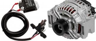
The generator for VAZ 2113-2115 cars is marked as 37.3701, and it is suitable not only for this family, but also for cars of the GAZ family. So, let's look at what parts this unit is made of.
VAZ generator device
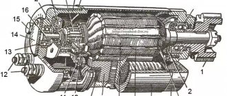
Generator 37.3701: 1 – cover on the side of the slip rings; 2 – rectifier block; 3 – rectifier block valve; 4 – screw for fastening the rectifier unit; 5 – contact ring; 6 – rear ball bearing; 7 – capacitor; 8 – rotor shaft; 9 – output “30” of the generator; 10 – output “61” of the generator; 11 – voltage regulator; 12 – terminal “B” of the voltage regulator; 13 – brush; 14 – stud securing the generator to the tension bar; 15 – pulley with fan; 16 – rotor pole piece; 17 – spacer sleeve; 18 – front ball bearing; 19 – drive side cover; 20 – rotor winding; 21 – stator; 22 – stator winding; 23 – rotor pole piece; 24 – buffer sleeve; 25 – bushing; 26 – clamping sleeve
Dismantling the generator
In order to dismantle the generator, you need to know its location. The diagram below shows not only the fastening device, but also the auxiliary fastening parts.
Layout of the generator and additional components
Removing the generator: 1 – tension bar; 2 – generator; 3 – generator mounting bracket; 4 – generator drive belt; 5 – generator drive pulley
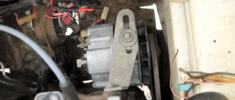
Visual location of the generator on the engine
Also, before removing the generator, it is worth understanding the diagram for connecting the part to the rest of the electrical circuit components:
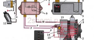
Connection diagram of the generator system 37.3701: 1 – battery; 2 – generator; 3 – mounting block; 4 – battery charge indicator lamp, located in the instrument cluster; 5 – ignition switch
Now that the basic circuits have been reviewed, you can proceed directly to the step-by-step process of removing the generator from the car. First of all, you will need tools, namely: keys for 8, 10 and 13; flat-head screwdriver. So, let's start the process:
- Disconnect the positive power cable of the generator.
Unscrew the generator power wires
Unscrew the bottom nut securing the generator
Unscrew the top nut securing the generator
Unscrew the tension bolt
Checking the serviceability of the voltage regulator in the generator
Before checking the generator voltage regulator, it must be removed and disconnected. Next, you need to make sure that the brushes are intact, have no defects or chips, and move freely in the channels of the brush holder. If brushes protrude less than 4.5 mm, the voltage regulator needs to be replaced.
The voltage regulator itself is checked using additional power sources: 12-14 V and 16-22 V.
Accordingly, the first source can be a battery, the second source can be a battery with 1.5-volt batteries connected in series to it.
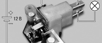
We connect the positive output of the battery to the output of the device, the negative one to the ground of the voltage regulator. A 12-volt light bulb is connected between the brushes.
If the regulator is working properly when voltage is applied:
- 12-14 V the light should be on;
- 16-22 V the light should go out.
In all other cases, the voltage regulator is faulty, cannot be repaired and must be replaced with a new one.
DIY replacement instructions
In the event of a breakdown, the repair of the DM consists of its replacement, which is done as follows:
First you need to turn off the ignition, open the hood and turn off the power to the on-board network; to do this, disconnect the battery. Once the battery terminal is reset, you will need to disconnect the pink cable responsible for activating the generator assembly. The wire itself is fixed with a bolt and nut; the nut itself will need to be unscrewed. Now you need to slightly loosen the tension on the top as well as the bottom nuts. Unscrew the tension screws and remove the strap. Inspect it - if the belt shows signs of damage - cracks, delamination - then it is better to change it immediately. If the strap is intact, set it aside. After completing these steps, you need to rotate the generator mechanism 90 degrees, this is done so that you can access the lower mounting screw. Unscrew it. Next, carefully inspect the body of the dismantled unit. If necessary, clean - there should be no dirt, especially on the connections. Dirt getting inside the generator housing can also lead to its incorrect operation and even failure.
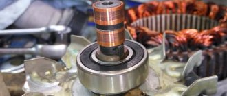
Bend the fasteners and remove the cover. Next, you need to clean the inside of the rings as carefully, but most effectively as possible. After this, all you have to do is dismantle the failed DM and replace it with a working part. When the installation is complete, the structure is reassembled in the reverse order. Do not forget to tighten the strap, just make sure that it is not overtightened, this is important
Having done this, you will need to start the engine of your car and diagnose the operation of the new DM.
replacing the diode bridge of the VAZ 2110 generator
What is the purpose of the part
It must be said that there is a diode bridge for the VAZ 2114 generator in several variations. The product may consist of 4 or 6 diodes. They are responsible for alternating current conversion. In this case, the specified pulsation frequency must be observed. If we consider the operating principle of the product, we must say that it is based on the bipolar rectification method.
Do not assume that the product plays the role solely of a converter. After all, it also acts as a valve, which is responsible for passing current in one direction. When the device is working as it should, current will flow into the system, but will not flow back to the starter. When a product malfunctions, current flows in both directions. The system will not work.
It is worth considering the advantages that the part has:
- The product may have bridge-type or half-bridge diodes.
- With the help of such a product, alternating current can be converted into direct current, and the lowest pulsation frequency will be observed. you need to understand that the lower the frequency, the better the system works.
- If necessary, you can install a special filter, which is also called a capacitor.
It is worth mentioning the issue of cost, which can vary from approximately 500 to 1100 rubles. The cost, in particular, depends on the manufacturer; you can give preference to inexpensive Chinese products or branded products, the quality of which cannot be questioned.
To decide which manufacturer to give preference to, you should ensure that the cost matches the quality. You can also look at online reviews and recommendations from experts.
Generator repair
In this manual we will look in detail at the VAZ 2107 - generator repair. For repairs, you will need a bearing puller, a mandrel for pressing and knocking out bearings in the generator cover. So let's get started:
Using a socket wrench, unscrew the nut securing the pulley and impeller, and use a screwdriver to hold the rotor from turning;
Unscrew the impeller fastening nut
We pull the pulley off the shaft, then the fan impeller, take out the key, take out the spacer washers;
We remove the pulley, impeller and spacers
We unhook the voltage regulator relay, first unscrew the fastening screws, and disconnect the wire block;
Unscrew the screws securing the relay
We take out the voltage regulator along with the brush assembly from the housing;
We take out the regulator and brushes
We unscrew the nuts securing the generator cover with a 10-mm socket and a ratchet, and remove the bolts;
Unscrew the nuts securing the cover
We rest the cover against a block of wood, helping by hitting the shaft with a rubber hammer, knocking down the front cover;
Removing the front cover
- Remove the cover and take out the spacer bushing;
- Check the condition of the front ball bearing. To do this, hold the cover tightly, turn and rock the bearing itself (the inner ring of the ball bearing) with your fingers. If excessive play is detected or the bearing is broken, it should be replaced with a new one;
- To replace a faulty ball bearing, use a size 8 wrench to unscrew the nuts securing it;
Unscrew the nuts to remove the ball bearing
We take out the bolts and washers
We select a suitable mandrel (punch) and knock out the bearing;
We take two wooden blocks, rest the edges of the back cover against them, and use a drift made of soft metal to knock out the rotor. If the surfaces of the lids are suddenly damaged, treat them with an abrasive wheel;
- We check the serviceability of the rear ball bearing using the method described in point 8;
- If replacement is required, remove it from the rotor using a puller;
Using a 8-mm socket with an extension and a ratchet, unscrew the nuts securing the diode block (diode bridge) and the leads from the stator winding;
Unscrew the diode bridge
- We take out the bolts and pull out the stator from the cover;
- We check the integrity of the stator winding. If the winding is damaged by mechanical action (scuffs, broken wires), or from overheating (blackened, burnt), then we replace the stator winding or rewind it, if time and price permit;
Pull out the stator winding
- Using a ratchet head, remove the generator output nut along with a washer made of an insulating substance;
- Now we can remove the diode bridge itself;
We take out the diode bridge
Using a Phillips screwdriver, unscrew the screw securing the capacitor and remove the capacitor. We remove the third bolt from the cover, which secures the rectifier unit.
Removing the third bolt
After completely disassembling the generator, we check the stator and rotor using a test lamp (watch the video). VAZ 2107 generator (repair and replacement) yourself is not such a difficult task, you no longer need the services of auto electricians. This will save you a lot of money.
