Let's look at what the design of a bearing puller is
A bearing puller is a device, usually made of steel, consisting of several claws and a metal rod.
This type of tool is used to firmly grip the bearing in order to remove it. The bearing removal process occurs due to tightening force. The ease of operation of the puller and the absence of the risk of injury depend on the quality of the design. Types of mechanical pullers:
- Pullers with two gripping arms.
- Pullers with three gripping arms.
- Internal pullers.
Pullers with two gripping arms are a fairly simple and reliable mechanism. Made from high strength steel alloys. Allows you to easily control the work process.
Pullers with three claws are the same pullers with two claws, but improved. As a rule, they are made of hard alloy tool steel.
Internal pullers are used to remove coupling shafts when the part is firmly attached to the structure.
There is also another unofficial type of puller - this is a special one. As a rule, it is used to remove generators, cylinders, and motors. These pullers are exclusive, made to your specific dimensions. This is the main advantage of such a product; you can be sure that the puller one hundred percent fulfills its promises.
Today we will look at how to make a reliable and, most importantly, simple puller that will help you out in difficult times. For this we need:
- A piece of thick pipe.
- Steel plate.
- Nut, bolt.
- Dye.
- Kernel.
- Welding machine.
- Bulgarian.
- Drill.
- Lathe.
- Sanding disc.
Kinds
Tools are divided into two groups.
- Hydraulic. When they operate, hydraulic traction is used; removal and landing are performed in semi-automatic mode. The main part of such a puller is a hydraulic nut, the internal cavity of which presses on a special piston. This, in turn, transfers the force to the desired part. The hydraulic model is in demand among owners of trucks and other large vehicles - with its help you can easily remove the most massive internal parts.
This is what a hydraulic bearing puller looks like
- Mechanical. They operate from human muscular strength and are in demand for mounting/dismounting wheel bearings. There are two-jaw, three-jaw and internal ones. Two-grip ones are the simplest. They are used where maximum process control is needed. Three-jaw machines are equipped with three paws and are used for working with the front hub and generator. Internal options are useful for removing ball and needle roller bearings; in addition, they can be used to dismantle various brass couplings.
This is interesting: Behind the car in Primorye
Mechanical three-jaw model
Bearing pullers can come in different sizes, but the most popular are universal ones. Their parameters can be adjusted manually, adjusting them to any diameter.
You can make different tools with your own hands, but it is best to make a universal three-jawed version - it is convenient to use.
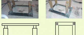
Diagram of a two-jaw puller
How a puller makes life easier for a car owner
Using this tool, you can dismantle bearings, bushings, pulleys, flanges and other components, remove or fix rings and gears, and repair chassis elements. It greatly facilitates the process of maintenance and repair of various parts of the vehicle. Using the right puller, you can quickly and easily replace a damaged element without the risk of damaging the machine elements connected to it. In addition, the tool can be used to work with hard-to-reach parts of the car, in a convenient position.
Products can have different designs, but the most common is the following - several gripping arms, which are shaped like hooks, and a threaded rod between them. Thanks to this structure, you can easily grab the required element and press the bearing out of it.
Design and principle of operation
The simplest wheel bearing remover is a device consisting of a metal rod and two gripping arms with ends bent inward attached to it. Thanks to the movable connection, it is easy to change the gripping distance. These paws can be used to lock and remove ball bearings, gears or rings. A tool with three gripping arms has more versatility because the arms can be deployed and used to remove internal elements. This device is also called an internal bearing puller. The most versatile is the combined extractor, which can be transformed from a three-legged one into a two-legged one. Its design has special clamps that make it easier to remove damaged elements.
Purpose and features of the device
If a hum or noise appears in the area of the car wheels that confuses you, this indicates that the wheel bearing has broken. It is not recommended to delay repair or replacement of this unit. If you are not a specialist in this field, then contact the nearest service station as soon as possible, where the car will be inspected and given a consultation.
However, it is not always possible to use the services of professionals; in some cases you have to act on your own. One of the most difficult repair operations is the dismantling of bearings. This requires special tools.
The most primitive wheel bearing puller is an item consisting of the following elements:
- metal rod;
- gripper arms (2 pieces) with ends curved inward.
The device has a movable connection and the gripping distance can be easily changed. The paws can be used to remove and fix the following:
- rings;
- ball bearings;
- gears.
If the tool has three gripping paws, then it has more possibilities, since the paws can be deployed and used to remove internal elements. It is called an internal bearing puller.
The most versatile device is the combined pressing tool, which has the properties of both a two-legged and a three-legged tool. Its design includes special clamps through which damaged particles can be easily removed.
Mounting and dismantling bearings requires applying manual pulling force to seat or remove one or another element. The success of your work, as well as your own safety, depends on how correctly you choose the tool.
Screw release mechanism
The second type of removable mechanism, which can be made from improvised means, is a screw release mechanism. It is perfect for replacing ball joints of classic VAZ models.
A special feature of the suspension design of these cars is that the upper and lower supports are located symmetrically to each other and the distance between them is not large.
It can be made at home only if you have a drilling machine, or you will have to go to a lathe. This puller consists of only two parts.
To make it, you will need a square or hexagonal rod with 17 or 19 key edges, the length of which is 7 cm. Using a drilling machine, we make a hole in this rod and cut a thread for a bolt of 8. Screw in the bolt and that’s it - the puller is ready.
Let's look at how it works using the VAZ-2107 as an example. To press out the upper support, you need to unscrew the lock nut, but not completely, you do not need to remove it. Then we install the manufactured puller between the pins of the supports with the bolt screwed in until it stops.
To squeeze out the finger, we take two keys - with one we hold the manufactured body, and with the second we unscrew the bolt until the finger falls off the socket. After replacing the upper support, we do the same, but with the lower one.
Screw L-shaped
The third type of removable mechanism, which you can make yourself, is also a screw mechanism, but it has shown itself to be excellent and allows you to work on any car.
To make it you will need a round metal rod with a diameter of at least 10 mm and a length of 15-17 cm.
From it you need to make an L-shaped blank with a shoulder length of 5 cm. That is, we take a rod, measure 5 cm on it, clamp it in a vice and use a hammer to bend it 90 degrees.
We cut a thread on the long part of the workpiece and select a nut.
All that remains is to make the thrust bar. It can be made in the likeness of the wedge described above. That is, we take a plate, but 0.5 cm thick. On one side we make a cut for the support pin.
If necessary, you can reduce the thickness of the plate on the cut side by grinding off the metal layer. The main thing is that the plate fits into the gap between the support body and the eye, but it is not too thin, otherwise it will bend during the pressing process.
On the other hand, from the cut we make a hole for the L-shaped workpiece. All that remains is to put the plate on the long part of the rod. If the thread is not long enough to squeeze out the finger, you can place several washers under the nut.
This puller works like this: Unscrew the nut almost completely, install the plate in the gap between the support and the eye, and turn the rod so that the short arm rests against the finger.
Then we simply tighten the nut, while the plate will act as a stop, and the short arm of the rod will squeeze out the finger.
Screw made from angle
Another screw puller can be made from a metal angle and a welding machine.
To do this, take a corner with sides 7-8 cm and the same length, and a thickness of 0.3-0.5 cm.
We make a cut in one of the sides to secure the mechanism to the eye. From sheet metal 0.3 cm thick we cut out two triangles that will act as braces. They need to be welded on the sides to the corner. This will significantly increase the strength of the structure.
We take a 17 nut and a long bolt for it. We weld the nut itself perpendicular to the cut so that its hole faces the cut.
So that in the future the bolt can be easily positioned on the same axis with the pin, before securing the nut by welding, a spacer must first be welded onto the corner.
All that remains is to screw in the bolt and the puller can be used.
These are the simplest types of removable mechanisms that you can make yourself.
In general, there are a lot of options, and with a little imagination and basic knowledge of plumbing, you can easily come up with and make your own puller.
We offer some drawings for viewing.
Tool for unscrewing the support
We will consider another type, which is used not for pressing out the finger, but for removing the support itself.
The fact is that on a number of cars (Peugeot, Citroen) the ball joint is screwed into the lever. Over time, the threaded connection sours, and it is quite difficult to unscrew this suspension element without a special tool.
But you can make the necessary puller yourself, rather than spending money on a factory one.
It is made from a 2" thick-walled pipe 8-9 cm long.
At the end of this pipe it is necessary to make 4 spikes with a width of 5 mm and a height of 7 mm, located at an angle of 90 degrees relative to each other.
That is, you should get 4 protrusions at the end of the pipe, evenly distributed around the circumference. This can be done using a hacksaw and a file, or with a grinder.
From the other end we make slits to a depth of 3 cm, dividing the circumference of the pipe into 8 parts.
Then we bend these petals to the center using a hammer, significantly reducing the diameter.
We take a 24mm nut and screw it to the end part, and then use a welding machine to seal the slots made.
It is quite convenient to work with such a puller - we put it on the support so that the spikes fit into special grooves on the support body.
In this case, the finger will pass through the manufactured tool, which will allow the locking nut to be screwed onto it, thereby securing the puller. All that remains is to use a 24mm wrench to unscrew the support using the welded nut.
Alternative method
Finally, we note that it is possible to press out the support pin or tip even if it is not possible to make a removable mechanism. But this method should be used only in extreme cases. To remove the finger you will need a pry bar and a hammer.
The pry bar is used as a lever and must be installed in such a way as to create a force to press the support or tip, for example, place it between the steering rod and the rack eye.
After creating force with the mount, it is necessary to apply powerful blows to the body of the eye with a hammer. If everything is done correctly, then after 2-3 hits the finger will pop out.
The disadvantage of this method is that the eye can be damaged due to shock loads, so it is advisable to use pullers rather than knock out the support.
Replacement methods
First way
So:
- In the first case, it is necessary to use a puller to remove the bearing;
- Simply carefully remove the bearing and replace it with a new one;
- After installation, all the steps above should be carried out in reverse order.
The main advantage of this method is the fact that the technician will not need to touch the camber adjustment bolt, which is very difficult to put in place later.
Bearing puller from the hub
If we talk about the disadvantages, we can note the following: the master will have to take a very uncomfortable position to perform actions. That is why it is necessary to prepare a lift and climb into the inspection hole.
But it is still very inconvenient for a car enthusiast to knock out the hubs in this position and press in the bearing assembly.
Second way
Consists of the following steps:
- To remove the bearing using the second method, you must carefully dismantle the steering knuckle and completely remove the hub;
- After this, the master will need to go to the workbench;
- The VAZ 2110 wheel bearing is replaced directly on the workbench;
- After this, everything is installed back, just as it was removed before.
Remove the retaining ring
Relying on the inner ring of the bearing, use a piece of pipe to knock out the bearing
Or press it out with a puller
Press a new bearing into the cleaned and lubricated hub.
This method is undoubtedly much easier than the first, but since it affects the camber, problems with adjustment cannot be avoided. Before you begin to unscrew the knuckle mounting bolts from the strut, you need to mark their position with chalk or a marker.
The first mark in this case will indicate the location of the adjusting bolt on the rack. The second mark will indicate the previous position of the fists.
After the master begins assembly, he will focus precisely on these marks. Of course, it will be difficult to achieve great accuracy and it will not be possible to return the parts to their place. But with careful work, installation errors can be minimized.
There are some steps to follow:
- The master puts marks;
- Knocks out the knuckle bolts;
- Unscrews the mounting bolts from the lower ball joint;
- The bearing must be knocked out of the hub;
- The retaining rings are dismantled;
- Using a vice, the bearings are pressed out.
Before reassembly, the space in the fists must be thoroughly and thoroughly lubricated.
This method is often used when repairing not only one bearing component, but the entire chassis. As a result of this method, it will also be possible to safely replace ball joints, silent blocks of levers and steering tips.
Third way
It is carried out in the following order:
- In this case, you will need to remove the entire rack completely;
- After all the components have been removed, the technician will need a special vice;
- The wheel bearing will be replaced at the vise and all parts will be reinstalled.
This method is the most complex and difficult because it requires the technician to dismantle the entire rack. In addition, it will be necessary to unpress the steering tip, and you also need to unscrew the fastening nuts, they secure the upper support to the body base.
Direct removal of this VAZ 2110 unit is carried out only after the entire rack has been removed from the car. And this process takes a lot of time.
Types of wheel bearing pullers
Study the summary table, which presents several main types of BSC, as well as specific recommended models.
| Type and model | Application | Average price, rub. |
| With 3 legs | Removing parts from axles and shafts, including rear hub ball bearing races. | 2000-3000 |
| With 2 legs | Removing parts from axles and shafts, including rear wheel hub bearings. | 1000-2000 |
| Cup with a set of mandrels | Removing and pressing parts into holes, including steering knuckles and front wheel hub bearings. | 6000-8000 |
What pullers are needed to remove and press in wheel bearings?
For the front and rear wheels, it is recommended to use two types of tools: with three or two legs and a cup puller - this is the minimum set of removable tools for the correct and safe removal and pressing of parts of hub units.
Wheel and bearing puller for VAZ and LADA cars
To replace the front and rear hub units on VAZs, according to the manufacturer’s recommendations, two types of removable devices are needed.
- Gripping tools are used to remove the ball bearing from the rear wheel.
- For pressing and pressing the bearing at the front wheel, cup types are used.
You can select models of these tools from the overview presented above. To select a cup puller, focus on the outer and inner diameters of your bearings, but as a rule, it is enough to read reviews and get advice from the seller.
For VAZ cars, for example, the model Force 9T0311, AV Steel AV-922722, MHRTOOLS MHR04039, NEO 11-829 are suitable. Suitable for pressing bearings into rear or front hubs, as well as into the steering knuckle. Insert the washer on the reverse side, tighten the nut, and put the key on the hold. Then rotate the stem nut clockwise.
A quick overview of wheel ball bearing pullers
It is impossible to choose a universal kit for all types of car repairs, since the range of actions is limited:
- a variety of shapes, sizes for charging to the starting position;
- limited work space.
Cup – “Forse 9T0311”
- Internal mandrels 34-80 mm.
- External mandrels 44-90 mm.
- The dimensions of the outer diameter of the cups are 44-90 mm.
- Rod (stud) with nuts.
- The plates fit a wide range of sizes.
- The steering knuckle remains in place.
- The set is included in the workshop press kit.
- Pressing-pressing takes place in one step.
Three-jaw – “KS TOOLS 630.3002”
Garage tool. Suitable for use in restricted access work areas.
- Long life if you follow the manual.
- The articulated design of the paws engages securely.
- Removing stuck parts from shafts and machine axles.
- Wide grip range - 20-230 mm.
- Maximum force - 4.5 tons.
- Screw rod dimensions: M18 x1.5 x 240.
- The dimensions of the bolts for the hinges are 19 mm.
Two-grip universal – “Kukko K-2030”
The tools from the set of the German manufacturer Kukko are well-thought-out forms of gripping mechanisms. On the traverse, the paws move along guides, and the suspension screws fix the specified position.
- Grasp the paws at an angle parallel to the axis of the tension force.
- Reliability of engagement.
- Maximum tension - 5.5 tons.
- The legs rotate 180 degrees.
- Wide grip range.
- Double acting.
- Suitable for use in confined spaces.
Read also: What is carbon steel made of?
Hydraulic pullers
You can also find hydraulic pullers on the market. The operating principle of hydraulic SSPs is similar to jacks. Designed for repair shop mechanics, no muscle power required, speeding up the repair time. Pay attention to the quality of the metal, the rotation of the screw rod, and the condition of the hinges.
- the force of influence on the pressed-in unit reaches 20 tons,
- operation time is reduced,
- the share of physical costs is reduced.
- limitation of the working area of application,
- the price is higher than a mechanical tool.
DIY bearing puller
To make a homemade product we will need:
- square metal rod;
- long bolt (screw);
- hex head mounting bolts;
- strip of metal.
First, we take a square rod and, using a grinder, cut three pieces from it. We adjust them to each other, as shown in the photo below.
Two long blanks are the gripper arms. The third blank is the connecting jumper into which the screw will be screwed.
Using a grinder, we cut out hooks at the bottom of the paws.
We drill holes in all three parts and cut the threads with a tap, and then connect them together with bolts.
You need to drill a hole in the connecting jumper for the screw. We grind the end of the screw on a grinder.
We make a bracket from a strip of metal, which we attach to one of the gripping arms of a homemade puller. You will first need to drill the mounting holes.
We also drill a hole at the end of the bracket and cut a thread in it. We screw in the bolt to limit the stroke of the second gripper arm.
Our homemade product is ready. Now you can try it out and see what happens in the end. This will require a shaft with a bearing.
The principle of operation of the device is quite simple. First, we hook the gripper paws to the bearing, and set the desired width between the paws by tightening the bolt at the end of the bracket.
Next, we rest the end of the screw against the end of the shaft on which the bearing “sits”, and begin to twist it clockwise - in the direction of twisting.
Twist until the bearing is free. This procedure usually lasts no more than 1-2 minutes.
Thus, the device turned out to be working, and the most important thing is that it is very easy to make. And no welding is needed.
For details on how to make a bearing puller for use in a workshop or garage, you can watch the video below.
A simple way to make a homemade removal device
This option is easier to implement, but the product will not be as convenient. You will need the following tools and materials:
- steel pipe, the internal diameter of which will be greater than the diameter of the bearing;
- metal plate more than 5 mm thick;
- Bulgarian;
- stud with nut or bolt with long thread;
- a few nuts.
- Cut a piece of pipe with the required parameters.
Cutting off part of the pipe - We mark all the necessary elements on a metal sheet, outline the pipe and bearing.
Marking out future details - We cut out the parts with a grinder and grind them to meet the exact parameters.
Cut parts - We drill holes for the bolt in the obtained washers.
Drilling holes for bolts - That's it, the remover is ready!
Ready puller
How to make a two-jaw wheel bearing puller: video
Let's move on to the work process itself. Stage one
The base of the puller is a piece of thick metal pipe, this is our frame. The pipe must be strong, with thick walls, otherwise it can easily bend. Pipe thickness from three millimeters. Cut off the desired piece using a grinder. Cut a window-shaped hole in the pipe. This can also be done using a grinder, but you will have to be patient; this is a long and labor-intensive process.
Second phase
We will make the lower and upper supports. We need a piece of sheet steel of maximum thickness. We cut a circle in it, you can also do it with a grinder. To simplify the work, you first need to cut a rectangle from the sheet, and then sand the sharp edges and the circle is ready. You only need two of these circles.
Finishing touches on the supports. Cut a hole for the bolt connection in the middle of the top support. The hole can easily be made using a drill and then drilled to the desired size using a lathe. Let's move on to the lower support. There you also need to drill a hole in the middle. The hole dimensions should be slightly larger than the axes from which you will remove the bearings. Then we cut out the part in the form of a triangle. At this point, the stage of work on the supports is completed.
Third stage
Now you need to weld two supports to the body. The seam must be strong and airtight. Let's start working on securing the nut. We screw the bolt into the hole and thread the nut. We secure everything with a welding seam, but do not overdo it with the current, otherwise the nut may melt. It can be attached externally or internally. With the nut located internally, the overall design of the puller seems more durable and reliable. The threaded rod will act as a handle. This makes it much easier to remove the bearings.
Fourth stage
All welds will need to be thoroughly cleaned. A sanding disc can easily handle this task. It will be convenient to collect the residual slag with a wire brush. The entire product is ready, all that remains is to coat it with special anti-corrosion paint. To ensure long service life of the structure. Before using the puller, you will need to lubricate the threads to improve the quality of work.
Let's test our homemade product. Bearings from a drill are suitable for testing. As we can see, the product copes with the task. Now you can repair your instruments without fear or risk, without fear of ruining them. The design is also suitable for removing bushings. If while using the puller you notice that the axle is too thin, you can place a stand under the bearing being removed or make a smaller puller. All in your hands.
Do-it-yourself universal bearing puller
We bring to your attention another interesting design that can be made from simple available materials.
First, cut a small piece from a square profile pipe. Or you can use a “stub” of a suitable size.
We make markings and use a grinder to cut out a triangular groove. We remove burrs.
On the opposite side of the workpiece we cut out three more grooves, but this time longitudinal.
We cut a piece of metal strip of suitable length, mark it, and drill holes in the workpiece. We weld a nut to the central hole.
We screw the threaded rod into the nut. Then you need to use two bolts and nuts to attach the metal plate to the profile pipe.
We weld a nut to the top of the stud. And to it we weld a handle made of a square rod.
Using this device, you can remove not only bearings from the shaft, but also pulleys of small diameter.
There is perhaps only one design flaw - there is no way to adjust the internal size between the hooks.
But in general, the device itself turned out to be quite good, considering that scraps of metal were used for its manufacture. Suitable for a home workshop.
For details on how to make a bearing puller with your own hands, we recommend watching the video below.
Homemade three-grip tool
This type of tool is the most difficult to manufacture, since the parts have a unique shape and require precise dimensions to mate them.
Required tools and materials:
- Grinder with cutting disc for metal;
- Sheet 1 m2 10-20 mm thick;
- Hairpin M18x1.5x 400 mm;
- Two nuts M18x1.5 height 20 mm;
- Pipe section outer diameter 89 mm, wall thickness 7 mm;
- M10 bolts for hanging the legs in the eyes;
- Welding machine.
The legs are cut from a sheet of 10-20 mm, L = 200-220 mm, the cross is made from an M18x1.5 nut, or cut out of a solid sheet with a grinder. Mark the contours of the crosspiece, cut it out, drill a hole in the center, then use an M18x1.5 tap to cut the thread.
Cup puller
The main part of the tool: M18 pin, cup and replaceable disks. A threaded bolt and nut can be picked up in a store, but the remaining parts will have to be ordered from a turner based on a sketch or drawing.
For VAZ 2108, 2109, 2110, 2111 washers are suitable - 30, 34, 37, 77 mm, bowl (ring) - 77 mm. For other car brands, find the original part number and its dimensions, and then cut out the appropriate washers and cups.
Double jaw wheel hub puller
Having amateur welding skills, two gripping devices are made from plates, nuts, and studs.
Not the easiest way to make a SSP in a garage; to assemble it you will need:
- Sheet 5 mm;
- Bolt M 14x1.5x 240;
- Bolts with nuts M6;
- Nuts M14.
Removable traverse for pressing out
This option is suitable for pressing and pressing the ball bearing out of the hub without removing it from the knuckle. The photo shows an example of such a design.
- One or two strong steel plates are taken, a hole for the bolt is drilled on top and a nut is welded.
- A second nut is welded coaxially from below.
- Next, holes are made for M10 bolts at equal intervals. The legs are cut from a 10 mm plate.
- The two plates are bolted together. Between them there is a long M16 bolt.
The only purchase is a crown to match the size of the ball bearing race. Cut the required washers from a 10 mm strip.
Tools and materials required:
- Bulgarian;
- Welding and drilling machine;
- Internal pipe section D 75 mm;
- Strip 70x30x5, 2 pieces;
- M6 bolts with nuts 4 pieces, lock nuts 8 pieces
- Thick-walled washer D 45mm.
Drawings for self-production of pullers:
Click on the drawing you are interested in to enlarge it.
FakeHeader
Comments 66
Can you just remove the hub with 2 bolts?
Yes. You just need to put washers under the nuts so that they don’t bite and you can moisten them with oil.
Hello, could you please tell me the inner diameter of the mandrel (the one into which the bearing fits)
I have a piece of 2 1/2 pipe, internal diameter 70mm, length 40mm. Outer diameter of the bearing 64mm.
Thank you! I’ll do it for myself according to your principle!
You're welcome. It is better to take a bolt with a fine thread and so that the threads are longer, otherwise putting washers in is a pain. The nut is also longer so that the load on the thread is less.
hmm, beautiful! the brain actually works as it should))))) I especially liked the device for removing the hub
long live the brain, ingenuity and GARAZhistochnyk of all the cool tools and adventurous craftsmanship hurray hurray
how complicated it is)))) the most necessary tool for repairing a car is a chisel and a sledgehammer.
The chisel and sledgehammer are already the last century, nanotechnology rules)))
Yes, an interesting solution that can be adopted. Well done, clever idea
+5 for consistency! You can immediately see the hands grow from where they need to be! And the head is in the right place! Well done!
Wouldn't it be easier to just remove the entire rack? All that remains is to remove the tip and unscrew the two nuts on top
Not easier. what the hell is this crap? And even when removing the hub assembly. (as they do at service stations) there is a chance to change the camber settings. And with the stand it’s a pain in the ass. )))
How can you reset the non-adjustable camber settings?
If it's easier for you to remove the entire rack. flag in hand. ) do.
You didn't answer) I remove stands every day according to the specifics of my work. It takes me no more than 20 minutes to remove, replace the bearing and install the strut in place from/to a Nexia/Lanos car. Of course it’s easier for me to take it off))) And respect to you for your efforts!
Should I answer you? I said everything I wanted.
You said: - "when removing the hub assembly. (as they do at service stations) there is a chance to change the camber settings.” I asked: “How can you reset the non-adjustable camber settings?”
Again. I say what is a hundred percent. remove the hub by disconnecting the steering knuckle (complete with hub) from the strut. And naturally the camber settings get lost. If you knock down the marks. I haven’t done this myself and that’s why I don’t recommend it to others... Same with the assembled stand. I didn’t do it, I don’t recommend it. What I advise is written above in the text.
Are you satisfied with my answer?
No) How can it be disconnected if it is welded? I have changed more than one thousand bearings on such a suspension and NOT ONE! I didn't do the collapse. And I didn’t unscrew the stabilizer links. And the bolts on the ball are placed with the nuts facing down.
"Again. I say what is a hundred percent. remove the hub by disconnecting the steering knuckle (complete with hub) from the strut. "
One of the bolts is elliptical. they adjust the camber. How did you not know this?! Because of your specialty, you should know how to adjust wheel alignment))
Which car's hub is in your photos? By chance, not this ca.d-cd.net/c974118s-960.jpg where did you see the eccentric? I'm talking to you specifically about the suspension that is in your photos, and these are Daewoo Lanos, Sens, Nexia, Chevrolet Lanos, Zaz Chance cars. Where is the camber on them? Don't mislead people!
In my photos, photos of my car. )) www.drive2.ru/r/lada/735604/ “Please, shave! ))" Meet our auto industry. )) Don't you know each other? ))
Do not lie! I already recognize the pendant from 1977))
In my photos, photos of my car. )) www.drive2.ru/r/lada/735604/ “Please, shave! ))" Meet our auto industry. )) Don't you know each other? ))
It's clear! I asked the topicstarter, but then you came in.
Wouldn't it be easier to just remove the entire rack? All that remains is to remove the tip and unscrew the two nuts on top
These are two extra nuts + a ball nut.
The ball is unscrewed in any case to pull the grenade out of the hub. All that remains is the tip and two small nuts from the support, but doing it on a workbench will be much more convenient.
Read also: Height of sconces on the stairs
Weak design for wheel bearings. It may be enough for 1 time, and only if you’re lucky and everything turns out well. Just the other day I was just changing the rear hub www.drive2.ru/l/3856310/ It’s unlikely that it would be possible to develop the required force with an ordinary bolt, and even with a regular thread. When pressing out the bearing, the 10-ton press worked at its limit.
I’ve already changed about a dozen bearings with this puller and everything is intact. I work in a service department, so even a 100-ton press can’t always handle it, I have to cut.
fag is a good company, I use it myself and recommend it to others
Yes, the puller is normal, what are you). In general, I use a vice, like a press, and a normal one.
5 points for the idea, but a solid score for the implementation. Sorry brother, but for me this is complete nonsense.
I bought myself a normal puller. It cost 850 rubles a couple of years ago. With a bearing costing 400 rubles and replacing it at a service station for 1500 rubles, the puller has already paid for itself 7 times. Everything is included there: a screw, two cups, stops, a stopper and claws for the clip. There is no need to saw anything with a grinder or beat it with a chisel. After the 7th bearing has been replaced, the whole process takes me 20-30 minutes at most.
Throw away this G... and buy a normal one. Enough for 4 lives, your great-grandchildren will still use it
Yes, I rent for half an hour with smoke breaks. Why then pay more? I don’t go to the service station and I have nothing to recoup.
Why pay more is a rhetorical question. I see several reasons here: 1. The branded puller is compact. There are no studs, strips or other scraps in it. Everything is folded into the outer casing and clamped with a bolt. Nothing is ever lost. I have it in an old mitten. 2. The branded puller is intuitive to use. There is no need to saw or knock anything down with a chisel. 3. It is ABSOLUTELY injury-proof. The mere fact that you can damage the hub if you cut it carelessly with a grinder, and then you will need to hit the hardened holder with a chisel, relegates your invention to the category of garbage.
Apparently, you never broke bearings in childhood and didn’t get hit on the forehead by fragments of a clip. Because otherwise you wouldn't be hitting the clip with a hammer.
What branded puller is this? Topicstarter has ZAZ, you have Chevrolet. Why are there bearings everywhere and all the diameters are the same?
Yes, you will be completely shocked now. Ready? We have front bearings from the VAZ Nine. The most common double row angular contact ball bearings
Why pay more is a rhetorical question. I see several reasons here: 1. The branded puller is compact. There are no studs, strips or other scraps in it. Everything is folded into the outer casing and clamped with a bolt. Nothing is ever lost. I have it in an old mitten. 2. The branded puller is intuitive to use. There is no need to saw or knock anything down with a chisel. 3. It is ABSOLUTELY injury-proof. The mere fact that you can damage the hub if you cut it carelessly with a grinder, and then you will need to hit the hardened holder with a chisel, relegates your invention to the category of garbage.
Apparently, you never broke bearings in childhood and didn’t get hit on the forehead by fragments of a clip. Because otherwise you wouldn't be hitting the clip with a hammer.
Have you forgotten what site you are on?! Yes, our people don’t need anything, just let them do something of their own with their own hands.
Yes, rather not on the site, but in the community.
By the way, do you happen to have an old 65mm concrete bit in your garage? I don’t have it, I don’t think you have it either, and it’s unlikely to be lying around behind the garage. So if you are going to repeat this wonderful puller, you will at least have to buy it. I bought one for myself for 450 rubles.
I guessed it right. there is no old one. there is a new one. but someday it may become unusable... he said that he assembled it from scrap metal... What he collected, well done. What about me? I bought myself a factory puller a long time ago. and I don’t really worry about this... but if only there were problems with him and with money. Perhaps I would have done it myself... What's wrong with that. A person can work with his hands and does what is convenient for him... I have knocked down rings before as he described. It's not that scary. You are intimidating people now...
Why pay more is a rhetorical question. I see several reasons here: 1. The branded puller is compact. There are no studs, strips or other scraps in it. Everything is folded into the outer casing and clamped with a bolt. Nothing is ever lost. I have it in an old mitten. 2. The branded puller is intuitive to use. There is no need to saw or knock anything down with a chisel. 3. It is ABSOLUTELY injury-proof. The mere fact that you can damage the hub if you cut it carelessly with a grinder, and then you will need to hit the hardened holder with a chisel, relegates your invention to the category of garbage.
Read also: How to connect a 220V modular contactor
Apparently, you never broke bearings in childhood and didn’t get hit on the forehead by fragments of a clip. Because otherwise you wouldn't be hitting the clip with a hammer.
1. I don’t need to fold anything compactly. I’m not afraid of losing something, there’s a lot of such stuff. 2. If I made a bullet out of shit, then I don’t even need intuition. With a chisel I can remove something that no puller will take. 3. Even with a puller you can break everything and the puller too. I have broken bearings since childhood and always wrapped them in burlap. I don’t recommend throwing out the branded puller, but there is a way out.
Homemade wheel bearing puller: drawings, photos, videos of a homemade device.
The author decided to make a homemade version of a tool for pressing out wheel bearings, an analogue of the one sold in stores.
Steel plates with a thickness of 8 mm and a pipe with a wall thickness of 7 mm were found as materials for manufacturing.
CV joint puller: types and method of self-production
A constant velocity joint performs the function of a universal joint, but its design is much more complex. In fact, this is a powerful ball bearing with a floating cage, to the cages of which the hub and axle shaft of the car's front suspension are attached. The hinge body is called a grenade due to its external similarity. The design is created as non-demountable.
Many manufacturers of spare parts offer to replace the entire worn joint. This is not an economical solution, since play appears only in one half - most often in the outer grenade.
CV joint puller: types and principle of operation
The general technique for removing a grenade from an axle shaft is quite simple - you need to pull the nodes in opposite directions with great force. This cannot be done by hand; you need a mechanical puller for the CV joint.
Such devices make it possible to save on visiting a car repair shop. You can purchase the tool at any auto store: both universal and for specific CV joint models.
Outer CV joint device
The hinge body contains a cage with balls, into which the axle shaft is inserted using a spline connection. Inside the so-called There are mechanical stoppers located on the glass, the size of which does not allow the assembly of the holder to be removed. The axle shaft is secured with a retaining ring, which is not accessible. This is not a power element; the stopper is designed to prevent the grenade from falling apart during transportation. However, using conventional tools, it is impossible to separate the splines without special pullers.
How to repair a CV joint with your own hands?
To replace the anthers or the entire outer hinge, a grenade puller is used. The device overcomes the resistance of the retaining ring and removes the splined joint from the cage.
How to make a puller from scrap materials?
The wedge-shaped design is the most complex (in terms of independent operation); industrial equipment will be required to manufacture the main elements. Let's look at the other options:
Thus, if you have a welding machine, you can make a critical tool yourself. Firstly, you don't have to run to the market and spend money. Secondly, you can make a more convenient device with your own hands than factory consumer goods.
Rear wheel bearing for VAZ 2108: price, part numbers, dimensions – which one is better?
Today there are many offers on the market, sometimes significantly different in price. Which rear wheel bearing for VAZ 2108 is better to buy? The answer is simple - it corresponds to the basic characteristics. Attention should be paid not to the price, but to the dimensions and manufacturer of the bearing.
In addition, the product must have a certificate of conformity to GOST 520-2002 or ISO 15:1998, protective holograms and be well packaged.
- The VAZ 2108 rear wheel bearing number in the international system is VA2B633313С.
- Marking (number) according to GOST: 6-256706AC17.
NOTE: Low-quality Chinese counterfeits should be avoided, giving preference to original Saratov Bearing (VBF) or Samara-made (SPZ-4) parts. The table below will help you choose the right spare part.
DIY CV joint puller
If you notice that the boots on the CV joints have become unusable (torn or cracked), it’s time to think about replacing them. Otherwise, you might end up buying a “grenade.”
We tell you how to make a simple device (puller) with your own hands, which can be used to remove an external “grenade” directly on a car without removing the box.
You can use leftover scrap metal to make homemade items.
First of all, you need to cut two metal plates from metal 4 mm thick (part dimensions - 40x170 mm. You will also need a piece of profile 30 mm long (size - 30x30 mm).
We clamp the profile pipe between two plates and scald it. At the edges of the plates, it is necessary to weld two pieces of round pipe (guides for changing sizes). The guides will accept ½ inch diameter tubing.
The clamp for clamping the shaft can be made from a piece of metal 4 mm thick, two threaded rods 100 mm long and a piece of round pipe with a diameter of ¾ inches.
Using a grinder, you need to select a seat for the shaft. We also drill two holes for the studs along the edges of the round tube.
We weld tubes with a diameter of ½ inch to the clamp so that the slot in the clamp is on the same axis with the hole that is intended for the CV joint shank.
In the guides and tubes with a diameter of ½ inch, you need to drill holes for the locking pins (bolts) so that you can fix the required size.
We clean the welds using a grinder, and the homemade product is ready. If you wish, you can paint it, but there is no particular need for this.
The operating principle of the puller is quite simple. We insert the CV joint into the device and fix it with a clamp.
We install the washer, screw on the nut and get to work. We tighten the nut and remove the outer grenade without any problems.
After this, you can replace the worn-out boot and service the CV joint.
Scrap metal grenade puller
Let's look at another simple universal design that can be made from any junk that can be found in the garage.
First of all, we cut four strips from 7 mm thick metal. We weld them together in pairs - as a result we get two identical blanks 14 mm thick.
Next, you need to cut out a “knee” from a piece of metal 7 mm thick using a grinder, as shown in the photo below.
Using the part as a template, we make a second blank of the same type. The result should be two identical “knees”.
The resulting blanks must be welded to a piece of pipe.
We make a homemade clamp for the shaft from thick metal. It consists of two parts - the lower and upper sponge. A long strip of metal is welded to the lower jaw.
We align the clamp in the center (coaxially with the pipe), and cut off the excess part of the plate.
We measure the length of the remaining piece of strip, cut it exactly the same, and weld it on the other side of the clamp.
We drill one hole in the “elbows”, and we drill the same holes in the side parts of the clamping device. We attach the clamp to the main structure. We also drill holes in the upper and lower clamp jaws.
We tighten the nut, and then perform the same action as in the previous case, when we considered the manufacture of the first version of the puller.
The disadvantage of this design is that the clamping device may become deformed due to heavy loads. The problem can be solved by making more powerful clamping jaws.
To be able to adjust the dimensions in the “elbows” of the device, it will be necessary to drill additional holes with a certain pitch.
At the last stage, all that remains is to clean the metal with a grinder and paint it with spray paint.
You can watch the video below for details on how to make a CV joint puller yourself using available tools and materials. This idea was shared by the author of the YouTube channel GarageInside.
Homemade outer CV joint puller
Do-it-yourself homemade outer CV joint puller: drawings, dimensions, photos and videos of homemade work in action.
The figure shows drawings of a device for removing CV joints.
The photo shows the design of the puller; it is made of two blanks with a wall thickness of 10 mm and welded to a nut with an outer diameter of 46 mm and an inner diameter of 30 mm. Two fastening plates were also made, two nuts were welded into one of them.
Using the device is quite simple, we fasten the plates with bolts
We also fix the device itself between the plates with bolts.
We unscrew it with a wrench and remove the CV joint from the splines.
In this video, the author shows in detail his homemade product in action.
