Overheating of the engine leads to serious problems: the pistons may jam, the cylinder block gasket may break, which leads to the need to overhaul the engine. To protect the power unit from overheating, it is important to maintain stable operation of the cooling fan. In this article we will discuss the operating principle of the device, its connection diagram, independent diagnostics and repair, as well as modernization of the control circuit. The instructions are fully suitable for VAZ 2115 and VAZ 2113 cars.
Operating principle
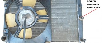
A fan is a device that allows you to increase the efficiency of a cooling radiator. The radiator takes heat from the engine and releases it into the air. This process is accelerated by blowing through the blades of an electric fan.
The coolant flows through a closed, sealed system. Its task is to remove excess heat from overheated engine parts. Hot antifreeze flows into the radiator, is cooled here and returns back. While in the radiator, the coolant passes through a system of thin tubes. The incoming air flow while the car is moving helps to quickly remove excess heat from the engine compartment.
But when the car is stuck in traffic or idling, the air flow stops cooling it. In this case, the cooling system may not cope with its task. An electric radiator fan is designed to create air flow artificially. The temperature for turning on the fan on a VAZ 2114 is 85 degrees Celsius.
Having received a signal that the permissible temperature value has been exceeded, the sensor starts the device’s operating mechanism. An artificial air flow is created that removes heat from the radiator. The mechanism operates until the temperature level drops to an optimal state.
The thermal switch then receives a signal that the normal temperature has been reached and turns off the fan.
The device consists of four plastic blades that are mounted on the EDF shaft. A special controller regulates the automatic operating mode. The thermostat is equipped with a solid filler that is sensitive to temperature changes.
There are main and additional valves. When the temperature reaches 85 degrees Celsius, the main valve opens.
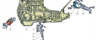
Solving problems with a faulty stove, unit design
If a motorist wants to deal directly with the heater design, he should know what the VAZ-2114 stove diagram looks like. For active operation of the heater, only a few important parts are needed, in particular a ventilation engine, an additional resistance resistor and a toggle switch through which you can switch the speed of the unit.
Due to the fact that the motorist is faced with a system malfunction, he must first diagnose the performance of the heating device by setting the switch to the first position, then gradually move it to the second and third speed modes. Using the lever you can adjust the direction of the air flow, while the last position will help regulate the choice of air temperature.
Where is the fan relay located?
It is located in an additional block.
4 – electric fan relay;
5 – electric fuel pump;
6 – ignition relay.
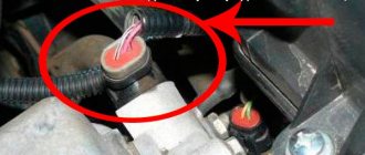
Relays and fuses may have a different order. Therefore, you need to focus on the color of the wires. The main relay is always located at the bottom. Find the relay that has a thin pink wire with a black stripe coming from it. It comes from the main relay through pin 85. Be careful! Do not confuse this with the red thin wire, which also has a black stripe and extends from the controller. And find a thick white wire with a black stripe (pin 87). This is where the cooling fan relay is located. There is always a fuse next to it. It is an element of the chain.
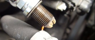
Cooling fan diagnostics
If signals appear on the dashboard indicating that the permissible temperature level in the cooling system has been exceeded, this may indicate that the fan on the VAZ 2114 is not working. The main symptom of the malfunction is that the mechanism does not start even with a significant increase in temperature. It is urgent to turn off the engine to prevent its elements from overheating.
The engine should not be operated with a faulty electric cooling fan. This may damage the cylinder head.
If the cooling fan on a VAZ 2114 does not work, the following malfunctions may be the cause of the breakdown:
- The fan switch sensor on a VAZ 2114 has failed.
- Lack of contact at the sensor connector.
- The wiring has broken.
- Electric fan relay faulty.
- The fuse has blown.
- Damage to the device's electric motor drive.
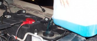
Unplug the device. Connect it to the battery terminal. Maintaining polarity. If a direct connection to an energy source starts the electric motor, then the drive is working. There may be problems with the wiring, the fuse, or the temperature sensor.
Now it’s time to diagnose the fuse. You don't even have to open the plastic box to do this. If the relay malfunctions, the horn stops working at the same time as the fan. Therefore, if you notice the loss of the sound signal, it means that the fuse has definitely blown. You can find it in the engine compartment in a small plastic box. We release the cover, pressed by two latches, take out the burnt fuse with tweezers and replace it with a new one.
But diagnosing a relay is quite difficult. Especially for those who are exclusively “you” with auto electrics. To check functionality, the easiest way is to find a working relay and temporarily install it. If, after installing a new device, the fan begins to work properly, then it is time to replace the old one.
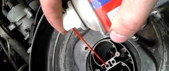
To diagnose the temperature sensor that supplies a signal to the radiator, you need to disconnect the connector from the sensor and start the ignition. The emergency mode will start, in which the electric fan will start blowing. If the fan starts late when the connector is disconnected, the sensor is most likely faulty. Replacing it will take no more than five minutes. You just need to unscrew two bolts using a Phillips screwdriver and install a new device in its place.
Even if a malfunction has occurred in the VAZ 2114 fan itself, this does not mean that it is time to change it. Sometimes you can simply replace a damaged bearing or brushes. But if the electric motor is faulty, it is much easier to purchase a new mechanism.
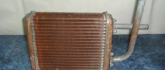
Knowledge of the design of the stove on a VAZ-2114, allowing you to independently replace the heater radiator
The design of the VAZ-2114 stove is such that to begin any work on the system, you will first have to drain all the antifreeze from the cooling system, dismantle the dashboard, and only then begin repair work.
To replace the radiator, the motorist will need several hours of free time, and the process should continue by removing the pair of hoses going to the tap pipes.
Loosening the clamps as much as possible will help simplify the task. The car owner will have to get rid of the hoses in the engine compartment that go to the tap pipes. After this, you can remove all the nuts holding the radiator. Removing the faucet from the panel will allow you to get rid of the rod holder and the device itself (the rod structure itself).
Removing the cover located on the gear shift knobs will help you continue the process. The car owner will be able to rid the car of the plastic lining covering the space under the handbrake. After this, you should unscrew and dismantle the floor covering located in the space between the chairs. Disconnecting the cabin air vent from the heating system will help you remove the unit and disconnect the connecting elements between the heater electric motor and the resistor.
In order to dismantle the heater, you only have to unscrew a couple of bolts. After replacing the main fixture, all removed parts should be installed in their respective places in the reverse order.
What to do if the electric fan runs constantly?
Sometimes another problem arises. Many car enthusiasts are interested in why the fan on the VAZ 2114 is constantly running?
There are four possible causes of the malfunction:
- a short circuit has occurred in the electrical circuit;
- the electric fan relay has broken down;
- The temperature sensor needs to be replaced;
- The electronic unit is broken.
Most often, the fan starts to work continuously as a result of a shorted wire. The electrical circuit remains on regardless of the signals from the temperature sensor and relay.
To troubleshoot the problem, you need to ring each wire and find the fusion point. Sometimes it is noticeable even upon visual inspection.
If ringing does not help identify the malfunction, you need to check and replace the fan relay. The cost of the device is low. Therefore, for diagnostics it is easier to buy a new relay and install it in place of the old one.
If this does not help, then you need to check the operation of the temperature sensor. After all, it is he who is responsible for turning on and off the electric motor of the VAZ 2114 fan.
If all other elements of the system are working properly, you need to check the electronic module. It rarely fails. If the problem still occurs there, you will have to perform a complete error reset. Sometimes only a complete flashing helps. Not everyone can do this work on their own. Therefore, it is better to seek help from a car service center.
It would also be useful to install a button to force the fan to start and turn off on the VAZ 2114.
This solution can be very useful if the breakdown occurs somewhere on the highway far from the city. In this case, using the button on the instrument panel, you can force the fan to cool the engine.
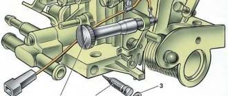
Schematic electrical diagrams, connecting devices and pinouts of connectors
All the main electrical circuits and modifications for connecting the liquid cooling fan (CO) in VAZ cars of various models are provided. What is the essence of VO’s work? An electric motor with an impeller on a shaft is installed inside a rectangular metal frame, with which it is attached to the back of the radiator. When voltage (12 V) is applied to the contacts of the drive, it begins to work, rotating the blades and creating a directed stream of air, which, in fact, cools the antifreeze or antifreeze.
If the cooling fan does not work, do not rush to contact a car service. You can determine the cause of the malfunction yourself. Moreover, it is not at all necessary to have special skills for this - just study the reference material from 2shemi.ru and follow the instructions for checking/replacing it.
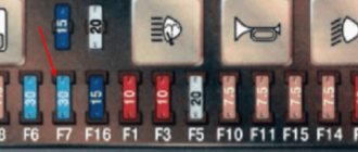
Circuit breakers
Auxiliary circuit with VAZ 2114 fuses
In fact, the VAZ 2114 wiring is always connected to fuses. Such fuses do not protect only the circuit of the generator and charging device, the mechanism for switching on the power unit of the machine, as well as the winding of the backlight cut-off relay.
Before replacing a failed electrical circuit fuse, you need to find out exactly the reasons for the wiring overload, as well as its elimination. Finding the cause will be much easier if you first read the following materials. Below is a list of fuses and their purposes.
The data (the name of the fuse and the electrical circuit protected by it) shows a complete list of all possible wiring fuses. For each car, their number may differ.
- F1. Wiring diagram for the rear fog lights, electric motors for the headlight wipers, housing for the control lamp and its shutdown, electric motor for the headlight cleaner.
- F2. Turn signals and turn signal relays, hazard warning lights, hazard lights.
- F3. The wiring of the lamp illuminating the interior is customized depending on the personal preferences of the car owner, the ignition switch light, the car trunk light, the engine functionality check indicator, the on-board computer, the brake light indicator, and the clock.
- F4. A plug for connecting a portable lamp, a plug that connects the heating of the stern and rear windows.
- F5. Connection diagram for SGU, radiator propeller electric motor, VIP signal relay.
- F6. Power window relay, power window connection circuit.
- F7. Wiring of the electric motor of the VAZ 2114 stove, electric motors for the headlight wipers and windshield washer, cigarette lighter circuit that illuminates the glove compartment, light bulb, relay for connecting the aft glazing heater winding.
- F8. Wiring diagram for the right fog lamp.
- F9. Left fog lamp diagram.
- F10. Electrical wiring for the side lights on the left side, an indicator that shows whether the side lights are on, a circuit for the engine compartment lamp, illumination of license plates, heating system levers and ashtrays, a cigarette lighter, a circuit for illuminating the switches.
- F11. Side lights located on the left side.
- F12. Right low beam design.
- F13. Left low beam design.
- F14. High beam device and left bulb. It is also an indicator for switching to high beam.
- F15. Right high beam design.
- F16. Wiring of turn signals, hazard light relay, relay responsible for the state of the lamps in the headlights, rear traffic indicator, lights signaling the following: low oil and brake fluid levels, whether the parking brake is on, low battery charge. Also a clock, an on-board computer and a generator excitation winding circuit during the start of the power unit of a VAZ 2114 car.
In addition to all the fuses listed above, which are located in the mounting block, there are 3 fuses. These fuses are located under the magazine shelf. The controller and relay circuit are also located here, with the help of which the VAZ 2114 power unit is controlled.
Fan connection 2108, 2109, 21099
Until 1998, on cars with the old mounting fuse block 17.3722 (finger type fuses), relay 113.3747 was included in the fan circuit. After 1998 there is no such relay.
Also, before 1998, the TM-108 switching sensor was used (the closing temperature of its contacts is 99±3ºС, the opening temperature is 94±3ºС), after 1998 the TM-108-10 with similar temperature ranges or its analogues from different manufacturers. The TM-108 sensor only works in conjunction with a relay; the TM-108-10, reinforced for high current, can work both with and without a relay.
Scheme for switching on the engine cooling fan on a VAZ 2109 with mounting block 17.3722
- Fan motor
- Motor start sensor
- Mounting block
- Ignition switch
K9 - Relay for turning on the fan motor. A - To terminal “30” of the generator
Scheme for switching on the engine cooling fan on a VAZ 2109 with mounting block 2114-3722010-60
- Fan motor
- Sensor 66.3710 for turning on the electric motor
- Mounting block
A - To terminal “30” of the generator
Relays and fuses VAZ 2114
F1 for 10 Amps (A) rear fog lights and rear fog light warning lamp. F2 for 10 A turn signal lamps, turn signal relay, hazard lights, hazard warning lights. F3 7.5 A lamps for interior lighting (both) and trunk, ignition lighting, powertrain control system control lamp, brake lamps, computer, if available. F4 20 A carrier, relay and rear window heating element. F5 20 A horn and its relay, cooling fan. F6 30 A power windows and their relays F7 30 A motor heater, headlight cleaner, windshield washer, cigarette lighter, glove compartment light bulb, rear window heating relay winding. F8 7.5 A right fog lamp. F9 7.5 A left fog lamp. F10 at 7.5 A left side marker, lamp signaling the inclusion of the side light, lamps for illuminating the sign, engine compartment, illumination of switches and instruments, instrument lighting switch. F11 at 7.5 A right side. F12 at 7.5 A right low beam. F13 at 7.5 A left low beam. F14 for 7.5 A left high beam and a light indicating that the high beam headlights are on. F15 at 7.5 A right far. F16 30 A - a light indicating insufficient oil pressure, brake fluid level, engagement of the parking brake, low battery, instrument cluster, relay for monitoring the health of lamps, indication of control systems, reversing lamps, turn indicators and their relays, as well as an alarm if turning mode is turned on, computer, generator excitation winding is turned on at the moment the engine starts.
Connection diagram for VO VAZ 2110
The circuit diagram for switching on the cooling fan of the VAZ 2110 on carburetor and injection cars is different. On cars with a carburetor engine, a thermobimetallic sensor TM-108 is used for this, and on cars with an injection engine, control is carried out by a controller.
Where is the fan relay located?
4 – electric fan relay; 5 – electric fuel pump relay; 6 – main relay (ignition relay).
Attention: the order of the relays and fuses can be arbitrary, we are guided by the color of the wires. Therefore, we find a relay from which comes a thin pink with a black stripe wire coming from the main relay (pin 85*) (not to be confused with the thin, red with a black stripe wire coming from the controller) and a thick power white with a black stripe wire (pin 87) (white and pink wires we need), this is the fan relay.
If the cooling fan does not work
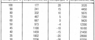
To drive the fan, a DC electric motor with excitation from permanent magnets ME-272 or similar is installed. Technical data of the electric fan and fan switch sensor:
- Rated rotation speed of the electric motor shaft with impeller, 2500 – 2800 rpm.
- Electric motor current consumption, 14 A
- Sensor contact closure temperature, 82±2 degrees.
- Sensor contact opening temperature, 87±2 degrees.
The cooling system fan may not turn on due to:
- electric drive malfunctions;
- blown fuse;
- faulty thermostat;
- a failed thermal sensor for turning on the cooler;
- faulty VO relay;
- broken electrical wiring;
- faulty expansion tank plug.
To check the VAZ fan electric motor itself, we apply 12 V voltage from the battery to its terminals - a working motor will work. If the problem is with the fan, you can try to repair it. The problem is usually the brushes or bearings. But it happens that the electric motor fails due to a short circuit or break in the windings. In such cases, it is better to replace the entire drive.
The BO fuse is located in the mounting block of the car's engine compartment and is designated F7 (20 A). The test is carried out using a car tester turned on in probe mode.
- In a car with a carburetor engine, you need to check the sensor - turn on the ignition and short-circuit the two wires going to the sensor. The fan should turn on. If this does not happen, the problem is definitely not with the sensor.
- For injection cars, it is necessary to warm up the engine to operating temperature and disconnect the sensor connector, disconnecting it from the vehicle’s on-board network. In this case, the controller must start the fan in emergency mode. The electronic unit perceives this as a failure in the cooling system and forces the fan drive to operate in constant mode. If the drive starts, the sensor is faulty.
Key Features
The main feature of the VAZ-2114 wiring diagram is that it is necessary to supply power to all components that provide fuel injection:
- Electric fuel pump.
- Injectors in the fuel rail.
- Sensor system.
Power is also supplied to the electronic control unit and ignition system. Moreover, on 8-valve engines, only ignition modules were installed, which, in essence, are a switch with built-in coils (there are two in total). But on 16-valve engines, one coil was installed for each spark plug. This scheme is more advanced, since if the coil fails, only one cylinder will fail.
The entire car is based on the design of its predecessor, the VAZ-2109. The body shape is the same, the suspension, ignition and fuel supply elements used, even the rear lights are the same. But there are significant differences in the design of the engine and gearbox. The new europanel looks much more attractive. It uses more attractive sensors and other devices.
Replacing an electric fan in a car
- We park the car on a flat surface and immobilize it with the parking brake.
- Open the hood and disconnect the negative terminal.
- Using a 10mm wrench, unscrew the fastenings of the air filter housing.
- Using a screwdriver, loosen the air duct clamp on the air flow sensor and remove the corrugation.
- We unscrew the screws securing the cover of the air filter housing and remove the filter element.
- Using a size 8 wrench, unscrew the air intake mount and remove it.
- Using a 10mm wrench, then an 8mm wrench, unscrew the nuts securing the fan casing around the perimeter (6 pieces in total).
- Disconnect the wire block on the fan connector.
- Carefully remove the fan casing along with the drive.
- Using a 10mm wrench, unscrew the 3 bolts holding the electric motor to the casing.
- We put a new one in its place.
- We install the structure in place, fix it, and connect the connector.
- We carry out further installation in the reverse order.
Control circuit modernization
The cooling fan on the top ten turns on at a temperature of 100-105°C, while the normal operating temperature of the engine is 85-90°C, so the fan turns on when the engine overheats, which naturally has a negative effect.
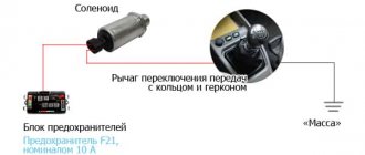
This problem can be solved in two ways: adjust the switch-on temperature in the “brains” or make a button. We'll focus on the second one. Turning on the fan from the button is very convenient: if you get into a traffic jam, turn it on, drive out, turn it off, and no overheating occurs.
A button for selecting the fan operating mode was installed in the cabin (always off, constantly on, automatically turned on via a sensor) - this “tuning” is not mandatory, but will be a very useful addition.
There will be a large current at relay contacts 87, 30, on the wire from the battery to the fuse and the fan ground, and therefore we must use wires there with a cross-section of at least 2 mm, otherwise the thinner wire will not withstand it and will burn out.
Video - connecting and checking VO
The domestic car VAZ 2114 (Samara-2) is built on the VAZ 21093 platform and is an improved version of it. The interior features a new instrument panel, a new steering wheel, an adjustable steering column, power windows and a new heater. All diagrams are taken from open sources and are intended to help in self-repair of the electrical equipment of this car. Enlarge images by clicking. The VAZ 2114 fuse box is located in the passenger compartment under the dashboard. When checking the electrical circuit of a VAZ-2114 car, you cannot check the serviceability of the circuits for a “spark” - this can lead to burnout of the current-carrying paths of the mounting block.
Car electrical equipment
1 — headlight block; 2 — gearmotors for headlight cleaners*; 3 — fog lights*; 4 — ambient temperature sensor; 5 — sound signals; 6 — engine compartment lamp switch; 7 — electric motor of the cooling system fan; 8 — VAZ 2114 generator; 9 — low oil level indicator sensor; 10 — washer fluid level sensor; 11 — front brake pad wear sensor; 12 — wire tips connected to the common windshield washer pump**; 13 — windshield washer pump; 14 — headlight washer pump*; 15 — wire ends for connecting to the rear window washer pump on VAZ 2113 and VAZ 2114 cars; 16 — low oil pressure indicator sensor; 17 — engine compartment lighting lamp; 18 — wire lug for connection to the wiring harness of the engine management system or to the wiring harness of the ignition system on carburetor vehicles; 19 — windshield wiper gearmotor; 20 — VAZ-2114 starter; 22 — coolant temperature indicator sensor; 23 — reversing light switch; 24 — low brake fluid level indicator sensor; 25 - battery; 26 — sensor for insufficient coolant level indicator; 27 — relay for turning on fog lights; 28 — mounting block; 29 — brake light switch; 30 — plug socket for a portable lamp; 31 — lamp for illuminating the headlight hydrocorrector scale; 32 — parking brake warning lamp switch; 33 — backlight lamp connection block; 34 — switch for instrument lighting lamps; 35 — steering column switch; 36 — alarm switch; 37 — front seat heating element relay; 38 — ignition switch VAZ 2114; 39 — rear fog light circuit fuse; 40 — fuse for the front seat heating elements circuit; 41 - door lock circuit fuse; 42 — front ashtray illumination lamp; 43 — ignition relay VAZ-2114; 44 — cigarette lighter; 45 — glove box lighting lamp; 46 — glove compartment lighting switch; 47 — heater fan electric motor; 48 — additional resistor of the heater electric motor; 49 — heater fan switch; 50 — heater switch backlight; 51 — lamp for illuminating the heater levers; 52 — gear motors for electric windows of the front doors; 53 — right front door power window switch (located in the right door); 54 — gearmotors for locking front door locks; 55 — wires for connecting to the right front speaker; 56 — gearmotors for locking rear doors; 57 — wires for connecting to the right rear speaker; 58 — door lock control unit; 59 — wires for connecting to radio equipment; 60 — headlight cleaner switch; 61 — rear window heating element switch; 62 — relay for turning on rear fog lights; 63 — block for connection to the heating element of the right front seat; 64 — switch for rear fog lights: 65 — switch for the heating element of the right front seat; 66 — fog lamp switch; 67 — switch for external lighting lamps; 68 — left front seat heating element switch; 69 — block for connection to the heating element of the left front seat; 70 — wires for connecting to the left front speaker; 71 — left front door power window switch; 72 — right front door power window switch; 73 — wires for connecting to the left rear speaker; 74 — side direction indicators: 75 — lamp switch on the front door pillars; 76 — lamp switch on the rear door pillars; 77 — lampshade; 78 — canopy for individual interior lighting; 79 — block for connecting to the wiring harness of the VAZ 2114 electric fuel pump; 80 — trunk light switch; 81 — instrument cluster: 82 — trunk lighting lamp; 83 — display unit of the on-board control system; 84 — trip computer (not in all models); 85 — block for connecting the wiring harness of the engine control system; 86 — rear external lights of the VAZ-2114; 87 — rear internal lights; 88 — block for connection to the rear window heating element; 89 — license plate lights; 90 - additional brake signal located in the spoiler.
Diagram of side lights, brake lights, interior lighting
Symptoms of VAZ 2114 DMRV malfunction: how to check the sensor
- Side light bulbs in headlights;
- Engine compartment lamp;
- Mounting block;
- Engine compartment lamp switch;
- Ignition switch;
- External lighting switch (fragment);
- External lighting indicator lamp in the instrument cluster;
- Lamps for side lights and brake lights in the outer rear lights;
- License plate lights;
- Instrument lighting regulator;
- Brake light switch;
- On-board control system unit; K4 - Relay for monitoring the health of lamps (contact jumpers are shown inside the relay, which must be installed in the absence of a relay); A - to power supplies; B - to the backlight lamps of switches and devices; C - to additional brake signal