One of the most common problems with domestic cars is the breakdown of any electrical devices; an electrical diagram will help you figure this out. The only solution to this problem will be to check the condition of the fuses. The topic of today's article will be the electrical circuit of a UAZ Bukhanka car on an injector-type engine.
UAZ Bukhanka
So, this article provides answers to these fairly common questions:
- What is the electrical circuit on a UAZ Bukhanka car with an injector type engine?
- How does the electrical circuit of the UAZ Bukhanka car work?
- Where are the fuses located on a UAZ Bukhanka car with an injector type engine?
- Repair of the mounting block.
troubleshooting
On any domestic car, problems periodically arise in the operation of electrical equipment. If you notice that the UAZ wiring is not working correctly, you need to diagnose it and check all the elements. If there are any malfunctions in the operation of electronic devices, first of all you need to check whether the fuses in the mounting block have burned out. If everything is fine with these elements, but the equipment still does not function, for example, if we talk about optics, then you need to check whether the light bulbs are working. If the lamps themselves are working, it is necessary to test the electrical part using a tester (the author of the video about testing car wiring is Ramil Abdullin).
If the Loaf refuses to start at all, you need to do the following:
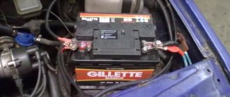
- First of all, check the functionality of the battery.
- With the battery charged, use a tester to test the circuit from the coil to the generator; often the reason for the inability to start the engine is breaks in the wiring. If there are breaks, the wires should be changed. If there is oxidation on the contacts, they should be cleaned.
- Starting the power unit will be impossible if there is no spark. To diagnose the presence of a spark, remove the high-voltage cable from the spark plug and bring it to the body. When you try to start the engine, a spark should jump between the cable and the body.
- If there is no spark, the problem may be carbon deposits and deposits on it. By the way, carbon deposits are often the cause of unstable engine operation and tripping. To get rid of such a malfunction, it is advisable to clean the spark plugs; step-by-step instructions for this process are presented here.
Have you encountered problems with wiring in your car?
Survey
- Yes
- No
- I don’t know (I don’t repair my car)
Loading …
About classic UAZ SUVs and off-road vehicles
In subsequent models, the tachometer received a signal from the ignition system, and the generator phase output was no longer needed; if the generator has one, it is simply not connected.
The video above just shows the option of starting a car unprepared for winter. The generator rotor is driven by a V-belt from the engine crankshaft pulley. Similarly, the excitation winding receives power through the brush voltage generator.
But there were some bugs. Summary Although there is still time before winter, you should worry about the electrical components of your Gazelle in advance. That is, the battery begins to charge at lower speeds than in the standard version.
The starter turns hard, cannot start the engine and there is not enough battery for the second attempt. All this can be avoided if you know what exactly you need to do... Technical aspects of winter operation The most obvious and pressing issue after a cold night in the open air is starting the engine. I give the load: long range, heater, heated glass, I also turned on the emergency lights.
- VAZ-2101, generator: connection diagram, repair, replacement
Read additionally: Install a two-gang switch with grounding
22.8. Electrical circuit diagram with ZMZ-402 engine
Installation kit: generator Thus, repairing a generator means replacing the diode bridge and replacing the bearings; in other cases, it is more profitable to exchange it for a reconditioned one. The reliability of the excitation circuit does not increase: the relay-regulator is still critical to a good “ground”.
Before removing the generator, let's check it again. So, ordinary power relays come to our aid.
The conclusion from here is this: the standard ZMZ ampere generator almost does not work at lower speeds. Calling an electrician he knew, he said two cherished words and everything fell into place - Put on the light bulb! Generator First you need to install a test battery.
Voltage regulator type The generator rotor is driven by a V-belt from the engine crankshaft pulley. Generator brushes Voltage regulator The generator must provide a constant voltage level to the network. By the way, the Gazelle Business wiring diagram is also not immune from such cases. Three-level generator voltage regulator. Three-level generator voltage regulator.
Did you like the article? Follow our channel for new ideas of useful car tips. Subscribe to us in Yandex.Zen. Subscribe.
Having become an indispensable vehicle, the Gazelle with the 402 engine still requires attention over the years.
Native 402 engine for Gazelle
Equipped with a ZMZ-402 carburetor engine, the car successfully exhausts its service life, and when the time comes for a major overhaul, many owners think not only about restoring, but also about reconfiguring its operation.
And since carburetor versions of power units have become a thing of the past, the question of the prospects for using a restored engine is urgent.
- Car generator circuit
Electrical circuit elements
The electrical circuit of the domestic UAZ is simple, since it is of the single-wire type. The standard wiring diagram for a UAZ “loaf” with a carburetor has the following features:
- the car body serves as a mass,
- The electrical diagram of the UAZ loaf with a carburetor and the actuators are equipped with a negative terminal connected to the housing.
The second feature is considered by experts to be an imperfection of this scheme.
The car owner is required to periodically determine the integrity and oxidation of contacts. If this occurs, the surface is carefully treated with sandpaper.
Meet UAZ 452
The car was a cargo-passenger version of an off-road vehicle with a 4x4 wheel arrangement. The Ulyanovsk Automobile Plant mastered production of the model back in 1965.
You can evaluate its capabilities by watching the following video:
The UAZ 452 is capable of transporting cargo weighing up to 700 kg in the back. In addition, it can tow a trailer weighing 850 kg. The vehicle became very popular not only in Russian off-road conditions, but was also successfully used in large cities in various capacities (pictured in the article).
In particular:
- Like a traffic police car;
- As a fire engine;
- Ambulance car;
- Grocery store;
- Utility vehicle, etc.
Electronic components
The electrical wiring of the UAZ 452 was a simple single-wire circuit.
Structurally, it had the following solutions:
- The role of the second wire was played by the metal body and the components and assemblies attached to it;
- All electronic components and actuators had a “-” displayed on the housing. The cost of such a solution justified the imperfection of the scheme.
For reference: The instructions provided for regular checking of contacts. When oxidized, they should have been cleaned with sandpaper.
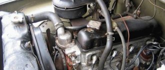
Power unit
The engine compartment is located directly inside the car, as this is due to its design.
Access to components and assemblies is also provided from the passenger compartment by removing the cover, which:
- Provided protection for the driver and passengers from the penetration of exhaust gases;
- Protected from dust and dirt;
- Served as an additional heating element (passive - from heating).
The previously used engine from Pobeda was replaced with a more modern engine from the 21st Volga. This was facilitated by the launch of a production line at the Zavolzhsky Motor Plant in 1964.
Note! Despite some skepticism regarding the inconvenience of servicing a cabover car with your own hands, years of operation have proven that there are no difficulties.
Passive vehicle safety
The design of the "Baton" with a cabover layout also initially raised a number of questions regarding safety. However, a series of crash tests conducted back in 1971 at the Dmitrov test site proved that in most emergency situations the driver and passengers of the UAZ 452 have a chance to avoid injury.
basic information
Fuses in a UAZ Bukhanka car are located in a special mounting block, which in turn is located in the air inlet box on the left side of the vehicle. The mounting block includes all the most important sections of electronic circuits, while supplying them with the necessary fuses and relays. The fuse box of the UAZ Bukhanka car consists of two lines with fuses and this entire structure is secured with a nut to the vehicle body. If you decide to remove the fuse lines, you will need to disconnect the battery.
The main elements of the electronic circuit include:
- Accumulator battery;
- Electronic fuel pump;
- Fuel mixture purification filter;
- Injectors;
- Engine control unit;
- Electronic ignition coil;
- Spark plugs;
- Idle speed sensor;
- Crankshaft sensor;
- Air damper sensor;
- Tachometer;
- Fan motor cooling the radiator;
- Electronic fan motor control relay;
- An indicator that monitors engine performance;
- Diagnostic connector.
Wiring diagram UAZ Bukhanka
If any failure of electronic equipment occurs, the current in the node that is responsible for this device will increase, resulting in a short circuit. The wire through which the current passes to the fuse burns out and melts, as a result of which the circuit breaks and the device turns off, but its integrity is maintained. That is, thanks to fuses, the main parts are protected from overheating in the event of a short circuit.
How to properly remove and install the mounting block?
If the electrical circuit is made with high quality, it will greatly facilitate the process of installing and removing electronic equipment. So, the algorithm for removing the mounting block:
- Disconnect the wiring from the negative terminal of the battery;
- Open the hood and remove the cover from the fuse and relay box. To do this, you need to press out 4 plastic latches;
- Move the rubber cover;
- Disconnect the upper block of the wiring harness from the block;
- We unscrew the 2 nuts that secure the block;
- We take out the block from the compartment, which is located in front of the windshield;
- We disconnect the lower blocks of the wiring harnesses from the block;
- Install fuses and relays in reverse order.
Repairing the mounting block involves replacing printed circuit boards. So, the algorithm for repairing the mounting block:
- Remove the mounting block;
- Remove the 8 screws that secure the bottom cover;
- Using a screwdriver, open the bottom cover;
- We check the condition of the tracks along which the current passes and the quality of soldering. If defects are detected, they must be eliminated, but if this is not possible, then completely replace the unit;
- Install the mounting block in reverse order.
Period from 1965 to 1984
During this period, the automaker equipped its products with electrical components available to the domestic industry. Some of them were known for a long time, others were experimental, as evidenced by videos from previous years, and which had to prove their suitability.
Connection diagram for headlights on UAZ 452 first editions
Lighting control
In particular, the controls and a number of main units migrated from its predecessor, the GAZ-69. Thanks to this, the price of the car remained the same.
On models of the first years of production, a foot light switch was installed, which had several operating modes:
- The first position activated the circuit for switching the low beam headlights and side lights;
- In the second position, the low and high beam headlight circuit was activated.
For reference: Turning on the headlights (low or high beam) led to the turning off of the front side lights.
Foot switch for headlights and parking lights
The modernized light switch has a different operating algorithm:
- The first position supplies power to the side lights only;
- The second position is side lights and low (high) beam headlights.
Caution: This algorithm with non-switchable dimensions is a mandatory requirement for passing MOT. The factory instructions give recommendations for reworking the old circuit, in which it is important not to mix up the contacts of the foot switch.
The most correct option is to replace the old switch with a modern one, which uses only 3 contact groups.
Also, on older versions of the “452” there was no alarm, so in the electrical diagram:
- An RS-57 breaker relay was installed (mounted in the wiring gap from the “+” terminal of the battery to the direction indicator switch);
- The middle contact of the relay closed the indicator light on the instrument panel.
See also the Ural motorcycle wiring diagram.
Ignition system
Ignition of UAZ 452 model 1968
Also on the “452” contact ignition was installed:
- The “+” wire from the battery supplied power to the ignition coil;
- From the coil, the high-voltage wire transmitted the impulse to the breaker (distributor) and further to the spark plugs.
Period from 1985 to 2013
In later modifications, with the advent of injection, some changes were made to the ignition:
- An additional resistance was installed in the “battery-ignition coil” circuit;
- A separate wire from the starter was laid to the coil wire connection terminal (past the additional resistance)
- On later models, an additional starter relay was installed in the circuit.
Control devices UAZ 452
For reference: UAZ vehicles also have different control devices. Some machines had an ammeter installed instead of a voltmeter. The UAZ 452 wiring made it possible to connect a voltmeter into the wire gap between the battery and the ignition system.
Conclusions: along with the car, the electrical circuit also changed. This factor should be taken into account when carrying out scheduled repair work in order to eliminate emergency situations.
See also the Moskvich 412 wiring diagram.
Generator connection diagram for VAZ 2107
Namely, to correctly adjust the operation of the ignition system elements. The voltage should be 13.6 - 14 Volts; when the headlights and heater are turned on, it should not drop below 13.4 Volts.
If it starts normally, then the starter and wiring are normal.
On the other hand: I have repeatedly noticed, especially when starting is difficult, on a connected battery the voltage after start is about 15.1 V, which is clearly more than normal.
Replacing the pulley.
The battery becomes a consumer and charging begins, the excitation winding of the generator is powered through the same circuit, only now not from the battery, but from the generator output. If there is a breakdown or break, then the winding will have to be replaced; it’s easier to replace the generator. Check the rotor winding. The rotor shaft rotates in ball bearings installed in the covers. Calling an electrician he knew, he said two cherished words and everything fell into place - Put on the light bulb! After this procedure, I had to straighten the impeller a little. This device was sufficient for breaking and tightening the nut. How to connect a generator to ZMZ 402
Features of electrical equipment
So, what features does the UAZ 452 electrical wiring diagram have? At the time of the start of production, the most difficult moment for the engineers and designers of the enterprise was the search for the highest quality elements and components.
In particular, we are talking about parts for the vehicle lighting system, as well as ignition, which is especially clearly seen in how the car’s cabin is filled:
- control elements for various transport systems;
- control devices for monitoring the condition of components and mechanisms.
External optics
At that time, designers had to resort to many freelance solutions in order to establish mass production of cars.
That is why:
- The UAZ electrical circuit includes an optics switch, which was borrowed from the GAZ 69. By the way, the latter is the predecessor of the Bukhanka.
- In addition, almost all the optics were borrowed from the GAZ 64 - these are lights, etc.
Ignition system
Loaf ignition system with designation of elements

