UAZ Hunter vehicles with a ZMZ-409 Euro-2 engine use a fuel supply system without a fuel tank switch tap. Fuel is supplied by a submersible electric fuel pump (submersible module) installed in the right fuel tank.
Fuel supply system for the ZMZ-409 engine on the UAZ-315195 Hunter.
From the fuel tanks, through a fine filter, the fuel enters the fuel rail, the relative pressure in which is maintained by a pressure regulator at 300 kPa. Increased fuel pressure eliminates the appearance of air bubbles and gasoline vapors in the fuel line, which interfere with the normal operation of the injectors.
Fuel injectors, which are fast-acting precision valves (normally closed), open to inject fuel into the engine intake pipe. The opening and closing of the injectors is carried out automatically according to the operation cyclogram of the corresponding output channels of the electronic control unit.
The injectors inject fuel into the hot and closed intake valves of the engine cylinders, which improves the quality of the air-fuel mixture. The control unit sets the duration and phase of fuel injection depending on the engine operating mode, crankshaft speed and load.
Excess fuel in the rail is discharged through the pressure regulator drain hole and the jet pump into the right tank. At the same time, fuel flows through injection from the left tank through the jet pump into the right tank.
After any maintenance or repair work on the fuel supply system of the ZMZ-409 engine, related to tightening connections, removing or replacing parts and assemblies, it is necessary to check the tightness of the system.
Leaks in connections are eliminated by tightening connections or replacing defective elements. The fittings of steel fuel pipelines must be tightened to a torque of 27±7 Nm. The rubber hose clamps are tightened to a torque of 3.5±0.5 Nm.
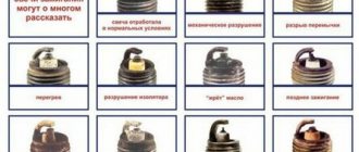
Signs of malfunction of the fuel supply system of the ZMZ-409 engine.
Clogging of the mesh filter of the submersible module in the right fuel tank, the fine fuel filter, the presence of dirt and mechanical impurities in the fuel tanks manifests itself in a deterioration in the dynamics of the car, unstable operation of the engine, especially under heavy loads.
If these signs occur, in order to avoid failure of the submersible module and the electric fuel pump, you should immediately rinse the right fuel tank and the mesh filter of the submersible module, and also replace the fine fuel filter.
When the ambient temperature is below 0 degrees, signs of clogging may be due to the presence of water and its freezing in the power system. If water is detected in the fuel, it should be drained and the fuel tanks with fuel lines should be washed with clean gasoline, and the fine fuel filter should be replaced. If after carrying out the above measures the nature of the engine operation has not changed and unstable engine operation is observed, then the following work must be carried out - Malfunctions of the ZMZ-409 fuel supply system and methods for eliminating them.
Fuel tanks UAZ Hunter.
The UAZ Hunter fuel supply system includes two fuel tanks of equal volume. The capacity of each is 35 liters. Maintenance of fuel tanks consists of periodically washing or replacing the filter of the submersible module in the right tank, washing the filter of the receiving tube of the fuel level indicator in the left tank and the tanks themselves. Periodically check that the tanks are securely fastened and, if necessary, tighten their mounting bolts. To wash the fuel tanks, remove them from the vehicle.
The filter of the submersible module or the receiving tube of the fuel level indicator can be washed without removing the tank from the vehicle; in this case, remove the submersible module or indicator through the hatch in the floor of the body.
Fuel tank caps must be kept clean and ensure that they are tightly closed. The catalog number of the sealed plug for fuel tanks of the UAZ Hunter is 31602-1103010. Plugs 2108-1103010-11 are also suitable for fuel tanks, provided that they are completely sealed.
Fuel evaporation recovery system for UAZ Hunter.
In order to reduce the emission of fuel vapors into the atmosphere, UAZ Hunter vehicles are equipped with a fuel evaporation recovery system. The left fuel tank communicates with the atmosphere through a separator, valve and adsorber.
While operating the vehicle, you must pay attention to:
— the presence of a strong smell of gasoline in the cabin, engine compartment where fuel and steam hoses and tubes pass through. If present, replace the adsorber; — correct installation of the solenoid valve for purge the adsorber; - cracks and damage to the adsorber - if any, replace the adsorber; — pinched and damaged fuel and steam hoses, damaged and leaking tubes and hoses must be replaced.
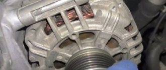
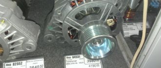
Electric fuel pump and submersible module 9P2.960.004 for UAZ Hunter.
The electric fuel pump and submersible module 9P2.960.004 are not repairable products. The service life of a submersible electric fuel pump is about 80,000 kilometers. During operation, periodically check and clean the contacts connecting the fuel pump to the on-board network. Pay special attention to the reliability of the ground connection. Rinse the mesh filter of the submersible module without removing the tank from the car through the hatch in the floor of the body.
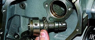
Fuel rail.
Designed for connecting the fuel line to the engine intake tract and for installing injectors. The fuel rail is a through pipe with four holes for connecting and fixing the injector inlet fittings.
Submersible electric fuel pump for ZMZ-409 Euro-2 engine
Maintenance of the submersible electric fuel pump during operation is carried out without removing the fuel tank from the car; for this, the fuel module is removed out through a hatch in the floor of the body, and comes down to the following simple operations: - checking and cleaning the contacts for connecting to the on-board network, with special attention paid to reliability ground connections. - replacing or washing its strainer - cleaning and washing the intake chamber of the fuel module
The electric fuel pump, usually BOSCH 0 580 454 035, cannot be repaired, only replaced with a new one. The declared resource is about 80,000 kilometers, but for various reasons it can fail even earlier.
conclusions
We are confident that the technical features outlined in this article will help you when carrying out scheduled and repair work. Using the included color schemes, taking into account the characteristics of the car, you can properly maintain your car.
See also the UAZ 469 wiring diagram.
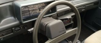
The UAZ Hunter is equipped with an electronic speedometer 85.3802 or 852.3802 produced by the Avtopribor plant, Vladimir. The speedometer measures and converts the rotation speed of the speed sensor shaft into speed readings, and the number of shaft revolutions into readings of the distance traveled by the vehicle.
Electronic speedometer 85.3802 and its modification 852.3802.
Speedometers 85.3802 and 852.3802 are completely identical, with the exception of the value of the PPP coefficient (speedometer indicating device), impulses per kilometer. Which specific modification of the speedometer will be installed on the car depends on the number of teeth in the drive and driven gears of the speedometer drive, and more specifically, on how many revolutions the drive produces per kilometer of distance traveled; more about this in this material.
The electronic speedometer is enclosed in a separate housing and consists of two main components: an electronic unit for converting input signals and a speed indicator. An electronic unit built on the basis of a microcontroller is placed on a printed circuit board and includes a liquid crystal indicator. The speed indicator consists of an actuator - a stepper motor installed on a printed circuit board, an indicator arrow mounted on the motor axis and a scale with marks.
The operating principle of the speedometer is to convert electrical impulses coming from the vehicle speed sensor into electrical signals that control the rotation of the stepper motor shaft on which the vehicle speed indicator arrow is mounted. At the same time, electrical impulses from the output of the speed sensor are counted by the conversion unit device and information about the daily and total mileage is displayed on the liquid crystal display.
Main characteristics of the speedometer 85.3802 and its modifications.
Speedometer indicator coefficient: for 85.3802 and 851.3802 - 3744 impulses per kilometer, for 852.3802 and 853.3802 - 6000 impulses per kilometer.
Speed sensors for speedometer 85.3802 and its modifications, their compatibility.
Electronic speedometers 85.3802 and 852.3802 are designed for operation in conjunction with speed sensors 34.3843, 341.3843, 342.3843, 352.3843 and AP 68.3843 RAR. Pin assignment of the three-pin speed sensor connector:
Connecting an electronic speedometer 85.3802 and 852.3802 to a UAZ Hunter.
When installing an electronic speedometer 85.3802 or its modifications instead of a mechanical speedometer, it is necessary to install a speed sensor on the transfer case instead of a flexible shaft on the speedometer drive and make the following connections:
To connect the speedometer to the electrical circuit of the car, you must use a socket block type KG-602207 suitable for the speedometer pin block. Purpose of the speedometer pin block pins:
The difference between connecting the speedometer 85.3802 and its modifications from connecting the speedometer AP 20.3802 from the RAR factory is the need to supply a non-switchable supply voltage from the battery to pin 3 of its socket block, otherwise each time the ignition is turned off, the daily mileage readings on the liquid crystal display will be reset.
Modifications of the electronic speedometer 85.3802 - speedometers 851.3802 and 853.3802.
According to the characteristics, the electronic speedometer 851.3802 is a complete analogue of the 85.3802, and the speedometer 853.3802 is an analogue of the 852.3802. The difference is that 851.3802 and 853.3802 are additionally equipped with an LED high beam indicator, the color of which, when turned off, matches the background of the scale, and when turned on, glows blue.
Characteristics, dimensions, block diagram, markings and connection diagram of the speedometer 851.3802.
Characteristics, dimensions, block diagram, markings and connection diagram of the speedometer 853.3802.
Mileage readings on the electronic speedometer 85.3802 and its modifications.
The liquid crystal speedometer indicator in working condition displays the total mileage counter in the top line and the daily mileage counter in the bottom line. Resetting the daily mileage is carried out by holding the button pressed for at least 1.5 seconds.
Self-diagnosis mode on the electronic speedometer 85.3802 and its modifications.
The electronic speedometer has a self-diagnosis mode that provides for the following: when you press and hold down the daily mileage reset button and then turn on the ignition switch, the speedometer needle should move from the initial position to the upper value of the reading range and back, all segments are displayed on the liquid crystal display.
After this, the speedometer needle should be set to the position corresponding to the measured value of the input signal, and the liquid crystal indicator should show the current values of the corresponding parameters. Possible speedometer malfunctions and methods for determining them are described in detail in a separate material.
before—>
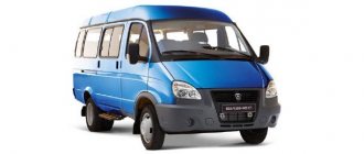
UAZ Hunter (UAZ-315195)
, colloquially known as “UAZ”, was produced in 2003, 2004, 2005, 2006, 2007, 2008, 2009, 2010, 2011, 2013, 2014, 2015, 2021, 2017, 2021, 2021 both with gasoline (injector and carburetor ZMZ -
409 ), as well as with diesel engines ZMZ-5143 in various modifications (UAZ-31512, UAZ-31514) and represents an updated version of the UAZ-469 and UAZ-3151 models that have been produced since 1972. In this publication you will find a description of the fuse and relay blocks of the UAZ Hunter 469 with diagrams and their locations.
Note the fuse responsible for the cigarette lighter. In conclusion, we suggest that you familiarize yourself with the complete electrical diagram and the original operating instructions. p, blockquote1,0,0,0,0—>
p, blockquote2,0,0,0,0—>
The design of the blocks and the purpose of the elements in them in your UAZ Hunter may differ from that presented and depend on the year of manufacture and the level of equipment.
p, blockquote3,0,0,0,0—>
Analogues of the submersible electric fuel pump of the ZMZ-409 engine
When replacing a submersible electric fuel pump with a new one, it is necessary to pay special attention to its characteristics, the pressure created and productivity; if the values are less than 300 kPa and 60 l/h , respectively, then such an electric fuel pump is not suitable.
Electric fuel pump Bosch 0 580 454 035 has been discontinued, its analogues that are suitable for replacement: Bosch 0 580 454 001 - pressure 300 kPa, capacity 110 l/h, Bosch 0 580 454 138 - pressure 300 kPa, capacity 100 l/h, Bosch 0 580 453 465 - pressure 380 kPa, capacity 90 l/h.
If you cannot find such electric fuel pumps, then temporarily supply BOSCH 0 580 453 449 - pressure 300 kPa, capacity 65 l/h.
It is not at all worth installing the very common and always available in stores BOSCH 0 580 453 453, which fits almost all VAZ models, although its pressure is higher than necessary - 350 kPa, but the productivity is only 60 l/h. The UAZ will start and drive, but you can forget about the dynamics; in addition, problems may arise with pumping gasoline between tanks.
Two fuse blocks with thirteen fuses each are located under the instrument panel to the left of the steering column. Illumination when working in the area of the blocks is ensured by turning on the interior lighting lamp located in the upper part of the fuse block mounting bracket.
The power fuse block is located on the front panel, under the hood. On UAZ-315143, UAZ-315148 vehicles there is a block with four fuses (Fig. 1), on other vehicles - with two (Fig. 2).
Before replacing a blown fuse, find out the cause of its burning and eliminate it. When operating a vehicle and when checking the electrical circuit, it is not allowed to use fuses that are not provided for in the design, and also to short the wires to ground (check the serviceability of the circuits “for a spark”).
Fuel system UAZ Hunter injector diagram
Model UAZ-315148, with ZMZ-5143.10 engine and BUDS-3.1 514.3763 and VS-9.2 974.3763 units.
For UAZ Hunter cars, model UAZ-315148, with a diesel engine ZMZ-5143.10 Euro-2, model 5143.1000400-50 - with a vacuum pump as part of the generator, and model 5143.1000400-41 - with a vacuum pump mounted on the cylinder block and a compact intake system, an engine control system with a control unit BUDS-3.1 514.3763 was installed.
On UAZ Hunter cars, model UAZ-315148, with a diesel engine ZMZ-5143.10 Euro-3, model 5143.1000400-80, an engine management system with a control unit VS-9.2 974.3763.000-01 was installed. Composition and elements of the control system of the UAZ Hunter, model UAZ-315148, with the ZMZ-5143.10 Euro-2 and Euro-3 engine, and the BUDS-3.1 514.3763 and VS-9.2 974.3763.000-01 units.
The engine control system ZMZ-5143.10 Euro-2 and Euro-3 is designed to start the engine, control it in driving and stopping modes. The main functions of the control system are:
- control of glow plugs, to ensure cold starting of the engine and its warm-up, - control of exhaust gas recirculation, to reduce the content of nitrogen oxides in the exhaust gases, - control of the operation of the electric booster pump, to improve fuel supply, - control of the fuel shut-off valve of the high pressure fuel pump (fuel pump) to stop the engine, - control of the glow plug indicator lamp on the vehicle's instrument panel, - control of the engine management system malfunction indicator lamp on the vehicle's instrument panel, - diagnostics of the engine management system, - the control unit also includes the ability to output signals to the tachometer.
It is not allowed to operate the ZMZ-5143.10 Euro-2 and Euro-3 engine with a burning diagnostic lamp (glow plug test lamp). Constant lighting of the lamp indicates the presence of malfunctions in the control system. If there are faults, the control system automatically switches to protected operation mode. As a result, starting, especially of a cold engine, deteriorates, toxicity and fuel consumption increase.
When the ignition is turned on, the diagnostic lamp (turning on the glow plugs) lights up for 1-2 seconds and goes out. If the coolant temperature is less than plus 23 degrees, the diagnostic lamp lights up with the simultaneous activation of the glow plug relay for a period of 3 to 15 seconds, then goes out.
If the diagnostic lamp does not go out, this means that a malfunction has been detected in the high-pressure fuel pump (HPF) lever position sensor, coolant temperature sensor, or the control unit itself. It is necessary to check the correct connection of these sensors, the serviceability of the sensors and the control unit.
If the diagnostic lamp goes out and any actuator does not work, you should check the correct connection according to the connection diagram, as well as the serviceability of the actuators: glow plug relay, fuel heating relay, recirculation control solenoid valve. Sensors of the control system of the UAZ Hunter, model UAZ-315148, with the ZMZ-5143.10 Euro-2 and Euro-3 engine, and the BUDS-3.1 514.3763 and VS-9.2 974.3763.000-01 units.
— Synchronization sensor, crankshaft position, BOSCH 0 261 210 113, 23.3847 or DS-1 (406.3847060-01), induction type. — Coolant temperature sensor 19.3828000, or 406.3828010, or 405226, semiconductor. — The high-pressure fuel pump lever position sensor is part of the injection pump, potentiometric type. Actuators of the UAZ Hunter control system, model UAZ-315148, with a ZMZ-5143.10 Euro-2 and Euro-3 engine, and BUDS-3.1 514.3763 and VS-9.2 974.3763.000-01 units.
— High pressure fuel pump BOSCH 0 460 414 217, 514.1111001-10. — Fuel stop valve built into the injection pump. — Electric fuel priming pump. — Four nozzles BOSCH 0 432 193 549, 514.1112010. — Electromagnetic valve for recirculation control 1902.3741, RKNU.1213008.
— Fault diagnostic lamp. — Glow plugs BOSCH 0 250 202 029, 514.3740000. — Glow plug relay 711.3747-02. — Fuel heating relay 90.3747-10. — Booster pump relay 90.3747-10. Schematic diagram of the control system of the UAZ Hunter, model UAZ-315148, with the ZMZ-5143.10 Euro-2 engine and the BUDS-3.1 514.3763 control unit.
Schematic diagram of the UAZ Hunter control system, model UAZ-315148, with a ZMZ-5143.10 Euro-2 engine and a control unit BUDS-3.1 514.3763 Schematic diagram of the UAZ Hunter control system, model UAZ-315148, with a ZMZ-5143.10 Euro-3 engine and a control unit VS-9.2 974.3763.000-01.
Schematic diagram of the control system of the UAZ Hunter, model UAZ-315148, with the ZMZ-5143.10 Euro-3 engine and the VS-9.2 control unit 974.3763.000-01 Designations of components and circuits on the control system diagram:
A1 - controller, engine control unit A3 - combination or instrument panel A8 - fine filter B3 - coolant temperature sensor B13 - switch sensor B14 - injection pump lever position sensor BR1 - synchronization sensor, crankshaft position sensor E1-E4 - glow plugs EK1 - fuel heater. FU1-FU9 - fuse HL1 - engine diagnostic lamp HL6 - glow plug lamp GB1 - battery KA1 - main relay KA6 - glow plug relay KA9 - fuel heater relay in the filter MP1 - fuel pump lever SA1 - ignition switch SA2 - ground switch XS1 — diagnostic connector Y8 — exhaust gas recirculation valve Y10 — engine stop solenoid valve Electrical circuits in the diagram: