The relays and fuses of the UAZ Hunter are significantly borrowed from its predecessor - a carburetor classic SUV. Due to the update of the configuration and power plant, the modern injection Hunter received additional inserts, which greatly complicated the circuit compared to the outdated modification. Separately, the 514 diesel engine should be highlighted. A fundamentally different system is used here. Added new wiring circuit fuses. Fundamentally, the inserts are divided into two modules – interior and engine compartment. They differ in purpose and installed elements.
Prevention measures
What preventative measures will help protect your car’s electrical network from malfunctions:
- When the engine is off, limit the use of electrical equipment, as the battery will drain faster;
- From time to time, diagnose the performance of the battery and check its charge;
- ensure reliable insulation of the wiring;
- never use homemade fuses.
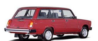
The main command vehicle of the armed forces - this is how the UAZ 469 SUV can be described. And indeed, having replaced the GAZ-69 in 1972, it secured this honorable duty for many years, proving the correctness of the design and main components with its endurance and reliability.
Historical reference
Traditionally, the UAZ 469 was produced in two versions:
- Cargo-passenger version - 7 seats and 100 kg of luggage;
- Commander version - 2 seats for passengers and 600 kg of luggage.
Industry standard 1945
According to the old vehicle classification system, in force since 1945, the UAZ 469 was produced under this name, using an alphanumeric name:
- The letter abbreviation UAZ stood for Ulyanovsk Automobile Plant;
- 469 is a serial factory index assigned by the enterprise itself to its models and developments.
1966 Industry Standard
Although at the time of the release of the UAZ 469 (1972) a new industry classification system was adopted (industry standard OH 025270-66), the car plant continued to use the name according to the old standard.
However, in 1985, the automaker was forced to change its name in accordance with current requirements:
- the car was assigned a four-digit number - 3151;
- According to the new system, the car can be called in the documentation as UAZ 3151.
The car plant named all further modifications and new models in accordance with current standards. In particular, the UAZ Patriot, which appeared in 2005, according to the industry classification, received the “correct” designation - UAZ-3163. For greater identification, the factory instructions contained both names.
Electrical equipment
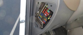
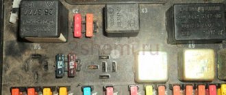
Each node is reliably protected from unexpected increases in current by special fuse links (fuses). They are assembled in a single mounting block, consisting of two lines, each of which contains 13 connectors with fuse links.
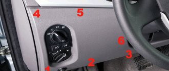
The compact unit is installed inside the car on the left side of the steering column. To make it convenient to inspect the elements of the block, a special backlight lamp with a built-in switch is fixed just above it.
In the engine compartment of the UAZ Hunter, another block is mounted, with strip-type fuses.
Each insert is responsible for a specific direction:
- starting switch;
- lighting fixtures outside the car;
- fuel filter heating;
- spark plug operation.
The purpose of the fuse links of the first and second blocks is to protect the electrical circuits of the equipment from overload and short circuit. Fuse housings come in different colors and are marked with the rated current.
The fuse links of the mounting block are installed in the following order.
| No. | What is he responsible for? | Note |
| F1 | Upper bar | Reserve |
| F2 | Side lighting | Right side of the body |
| F3 | Low beam | |
| F4 | Long range lighting | |
| F5 | Fog lights | |
| F6 | Lamp for illuminating the installation site of the mounting block | |
| F7 | Tail light brake lights | |
| F8 | Alarm | |
| F9 | Klaxon (beep) | |
| F10 | Rear license plate lamps and instrument lighting on the control panel | |
| F11 | Responsible for the cigarette lighter | |
| F12 | Rear fog lamp (if equipped) | |
| F13 | Reserve | |
| F14 | Bottom bar | |
| F15 | Side lighting | Left side of the body |
| F16 | Low beam | |
| F17 | Long range lighting | |
| F18 | Fog lights | |
| F19 | Reverse (white light) | |
| F20 | Direction indicators (right and left) | |
| F21 | Heater operation | |
| F22 | Windshield wiper motor and washers | |
| F23 | Interior lighting of the car and connecting the engine compartment lamp | |
| F24 | Reserve | |
| F25 | Operation of devices and alarms (sensors) | |
| F26 | Reserve |
What do fuse links and tape links protect?
The UAZ-Hunter fuse box provides protection for the following components and assemblies:
- Dimensional and main lighting elements.
- Turn indicators.
- Cigarette lighter.
- Sound signal.
- "Janitors".
- Interior lighting.
- Brake warning lights.
- Backup equipment.
- Interior heaters.
- Radio equipment.
- Additional pump for the heating system.
- Instruments and indicators.
Where is the relay located in a UAZ Bukhanka car?
The all-wheel drive vehicle UAZ-452 (“loaf”) appeared in the 60s of the last century, and is still popular. But UAZ often breaks down, and in order to eliminate the malfunction, you need to know the location of its main relays.
Where is the fuel pump relay located?
The fuel pump relay is a device that supplies or cuts power to the fuel pump. It controls the fuel pump and performs a number of additional functions depending on the make of the car.
Typically, in “loaves” the fuel pump relay is installed in the area of the injection control unit, under the hood, behind the battery. Sometimes it can be found under the dashboard near the fuses.
Where is the charging relay located?
The charging relay consists of a reverse current relay, a regulator and a limiter. The reverse current relay turns the generator on when its voltage increases, and turns it off when the battery voltage increases.
The regulator controls and limits the current within 13.8 - 14.8 V, and regulates the charging current. The limiter protects the generator from overloads, working on a similar principle to the voltage regulator - it includes additional resistance in the winding circuit as the current increases.
The charging relay works in conjunction with the alternator under the engine hood on the right side.
Where is the starter relay located?
In UAZ there are two types of starters - 42.3708 and 4211.3708–01. They themselves are installed on the left side of the engine (in the direction of travel of the car).
The starters are equipped with an electromagnetic traction relay and a lever drive with a roller freewheel clutch. The blocking relay is located in the medical compartment and serves to prevent the starter from turning on when the power source is connected.
The wire from the relay goes to the central contact of the variator (with three coils) or to the coil connection contact (with two coils). This helps to strengthen the spark during engine starting.
Where is the turn signal relay located?
In UAZ vehicles, the turn signal circuit includes a steering switch, a turn relay, an hazard warning light and six bulbs.
This system is protected from overloads by several fuses:
- F8 – 10 A (for alarm);
- F20 – 7.5 A (for direction indicators).
Turn signals without a relay will not blink, so its malfunction is easy to determine.
It is located in the mounting block, on the left side, at the driver’s feet. In ambulances and utility vehicles such as UAZ, the turn relay is installed on the partition, behind the driver's seat.
If the relay malfunctions, it must be removed, and the use of metal objects is not allowed.
Blocks in the cabin
Fuse box
It is located under the panel, slightly above the steering rack.
Photo - diagram
Description
p, blockquote 7,0,1,0,0 —>
| 1 | 25A Reserve |
| 2 | 5A Side light right side |
| 3 | 7.5A Low beam right side |
| 4 | 10A High beam right side |
| 5 | 7.5A Fog lamp right |
| 6 | 5A Fuse Box Lighting, Portable Lamp Socket |
| 7 | 7.5A Brake lights |
| 8 | 10A Direction indicators in hazard warning mode |
| 9 | 20A Horn |
| 10 | 7.5A License plate lights, instrument lighting, switches |
| 11 | 15A Cigarette lighter |
| 12 | 5A Rear fog lamp |
| 13 | 10A Radio equipment |
| 14 | 25A Reserve |
| 15 | 5A Side light left side |
| 16 | 7.5A Low beam left side |
| 17 | 10A High beam left side |
| 18 | 7.5A Fog lamp |
| 19 | 5A Left reversing light |
| 20 | 7.5A Turn signals in turn signal mode |
| 21 | 10A Heater |
| 22 | 20A Wiper motor, windshield washer |
| 23 | 7.5A Lighting lamps, engine compartment lamp |
| 24 | 15A Reserve |
| 25 | 5A Devices and signaling devices |
| 26 | 10A Additional pump for heating system UAZ 315148 |
Fuse number 11 at 15A is responsible for the cigarette lighter.
Relay block
It is located under the panel, near the left drain.
Scheme
Designation
- low beam headlight relay
- headlight high beam relay
- fog light relay
- tailgate wiper relay
- rear fog light relay
- windshield wiper relay
- turn signal relay
Electrical wiring components for UAZ 469, UAZ 390945 and other models
The electrical circuit of the UAZ 3151 4 includes 69 positions; it is possible to additionally connect special fog lights, but the installation of a switch type 343.01.03 is required. It will be mounted directly on the dashboard in a convenient location. The general wiring diagram of a machine includes an extensive list of different devices.
This is a front light, headlights that are easy to replace if necessary. An audio signal is also connected to the general system. Further, the UAZ wiring diagram includes a special fuse and additional resistance. The circuit has a connection to the side direction indicators, and a switch for the heater is located right there.
The wiring supplies the generator, there are connection points for the light that illuminates the engine compartment, and outputs for the heater fan motor. Modern UAZ electrical wiring includes spark plugs powered by it. A relay is installed for indicators; it is used to ensure the operation of emergency and turn signals.
The electrical circuit has outputs to a coil, a starter relay, there is a special sensor-distributor, and a switch. In one area there are the following points: turn off the masses, hazard warning lights, battery, electric washer. There is a separate connection for the fuse box and the following sensors:
- emergency pressure for oil;
- fuel readings;
- for oil pressure indicator;
- overheating of used coolers;
- temperatures of the coolers used;
- determining the brake fluid level.
Relationship between motor and circuit
When releasing the car, the designers equipped the UAZ “Hunter” with three types of power plants. This move made it possible to choose a car that satisfies the needs of the consumer. However, the move used made changes to the electrical circuit of the car. Thus, the electrical circuit of the UAZ Hunter diesel is different in comparison with the gasoline unit. In addition, the electronics used on the motors have not been used before.
Install on the car:
- Electronic ignition control unit;
- Electronic filling that controls the motor;
- Sensors for reading engine indicators;
- Electronic execution mechanisms.
| Power plants used on the UAZ “Hunter” | |||
| Motor model | UMZ-4213 | ZMZ-409.10 | ZMZ-5143.10 |
| Motor type | Gasoline (injector) | Gasoline (injector) | Diesel |
| Engine volume, (l) | 2,890 | 2,693 | 2,235 |
| Motor power, (hp) | 104 | 128 | 98 |
| Cylinders, (pcs) | 4 | ||
| Camera, location | row | ||
| Chamber, section, (mm) | 100 | 95,5 | 87 |
| Displacer stroke, (mm) | 92 | 94 | 94 |
| Compression | 8,2 | 9,0 | 19,5 |
Technological solutions have made vehicle diagnostics and updates easier. It is worth noting the contribution made by the electronic system that controls the engine. The main task in the unit is performed by an electronic controller. Errors in the operation of the power plant are recorded and transmitted to the reading device in the form of a digital code.
The information is read through the diagnostic connector. Connecting the device and then deciphering the code gives an idea of where the failure occurred and how to fix the problem. Performing diagnostics involves performing manipulations.
UAZ diagnostic connector:
- The algorithm of actions is as follows:
- Set the ignition key to the “off” position;
- Remove the battery from the car for 10-15 seconds. The “self-diagnosis” mode of the controller starts;
- We connect the battery back to the car;
- We start the engine and let it run for sixty seconds;
- We connect the terminals of the diagnostic connector with a separate conductor, this activates the “self-diagnosis” mode;
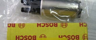
Generating device Bosch 6 003 GB5011:
Confirmation of activation will be code “12” displayed three times on the reader, subsequent codes are recorded errors.
New electric current-generating devices are used to power the car and charge the battery. At the initial stage, the wiring diagram of the UAZ Hunter injector 409 engine included an “Iskra” product, the diesel engine had a “Bosch 6 003 GB5011”. Since the circuits of the generating devices are different, the connectors and conductors used under the hood of the car are also different. In the latest models, the manufacturer began to install a generating device of its own design (9422.3701). You can also read about Fuel consumption per 100 km UAZ 469.
Main relay and UAZ Hunter electric fuel pump relay, ECU fuses
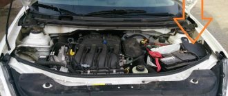
There are a lot of different relays in the UAZ Hunter, most of them controlling the headlights, turns and windshield wipers are located in a visible place on the left side of the front panel on the driver's side. However, there are two relays located in the engine compartment, about which only a few lines are written in the official operating manual, this is the main relay and the electric fuel pump relay of the engine management system.
Meanwhile, the serviceability and performance of these two power relays directly determines whether you can even start the car’s engine or not, since through the relay, the main ECU supplies power to all actuating electric mechanisms and sensors of the system, which have a rated supply voltage of 12 Volts, and the electric fuel pump relay supplies voltage to the electric fuel pump of the fuel supply system and to the heating circuit of the oxygen sensor.
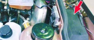
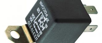
The main relay and the electric fuel pump relay are installed in the engine compartment on the front panel above the engine, to the right of the vacuum brake booster, when looking along the vehicle. Both relays are exactly the same, with the same catalog number 90.3747-10, and have no visible external differences.
Relays are four-contact, electromagnetic type with normally open contacts, designed to control power circuits up to 30A. You can distinguish them externally by the following feature: thicker wires with a larger cross-section are suitable for the main ECU relay block.
Structurally, the power relay 90.3747-10 consists of an insulated base with four pressed-in pins and an electromagnet coil mounted on it with an armature and a movable spring-loaded rocker contact, and a plastic housing pressed along the contour of the base. The relay is connected to the wiring harness using four-pin sockets.
— Power supply range: 8-16 Volts — Rated voltage: 12 Volts — Control current: no more than 0.2 Ampere — Operating voltage: not less than 8.0 Volts — Release voltage: 1.5-5.0 Volts — Maximum current in the power circuit: 30 Amperes— Active winding resistance: 80+-10 Ohm
Fuses for power circuits of the engine electronic control unit (ECU).
Next to the main relay and the electric fuel pump relay, two blade fuses are attached to additional blocks. 10 ampere, red - to protect the ECU power circuit coming from the ignition switch, and 20 ampere, yellow - to protect the ECU power circuit coming from the battery, the electric fuel pump power circuit and the oxygen sensor heating circuit.
The need for protection and periodic maintenance of the relay.
The location of the main relay and the electric fuel pump relay in the engine compartment is very contradictory; on the one hand, there is good access to them, and on the other, they are constantly exposed to condensation or rainwater that penetrates through the gap between the body and the rear of the hood. The relays are practically recessed in thick sound insulation and are screwed directly through it with their brackets to the panel.
Water and condensation flowing down the sound insulation end up on the pads, relay and fuse contacts, which begin to quickly corrode and, accordingly, do not provide good contact or even fail. To protect and reduce the negative impact on relays and fuses, it is advisable to somehow move them away from the sound insulation, for example, by taking longer screws and re-fastening them through thick rubber washers, or even by making some kind of protective casing for them.
In any case, these relays, along with the fuses, must be removed at least once a year and their contacts must be cleaned of any corrosion that has arisen; this will directly affect the operation of the engine, you will feel it immediately, especially when it is idling.
Diagnosis of faults associated with the main relay and the UAZ Hunter electric fuel pump relay.
Error codes for the engine management system with the Mikas 7.2 ECU associated with the main relay and the electric fuel pump relay, other external signs of malfunction of them or their electrical circuits, troubleshooting methods, as well as analogues and options for replacing the main ECU relay and the UAZ Hunter electric fuel pump relay are discussed in detail in the following material.
Purpose and location of UAZ Hunter fuses
Relay and fuse blocks VAZ 2112: description and explanation
The manufacturer installed pin fuses and power plate elements on the machine. Plate ones have high permissible loads.
The fuse box of a UAZ Hunter car is necessary to protect electrical wiring from fire in the event of a short circuit and overload. Fuses connect the positive wires of consumers to the power source. The machine has two power sources, a generator and a battery.
There is a fuse element inside the pin fuse.
It is designed for a certain load. If the permissible load is exceeded or a short circuit occurs, the fuse element burns out, disconnecting the consumer and the power source.
UAZ Hunter fuses are installed in strips of 13 pieces. The block contains 2 planks. Each fuse is designed to protect a specific circuit. Depending on the intended load of the circuit, the fuse ratings differ. The rating is marked on the fuse body. The color of the pin fuse body corresponds to a specific rating:
- Orange color - the fuse element is designed for a current of 5 Amperes;
- Brown – has a rating of 7.5 A;
- Red color – corresponds to a fuse element with a rating of 10A;
- Blue - has a rating of 15 A;
- Yellow – 20 Ampere;
- Beige color - corresponds to a 25 A fuse.
ATTENTION: It is prohibited to install a fuse whose rating does not correspond to the value indicated on the block strip. Failure to comply with this rule may result in an electrical fire.
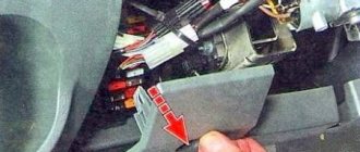
The UAZ Hunter fuse box is located in the passenger compartment under the front panel on the left side of the steering wheel.
The strips are installed in a plastic housing and secured to it with bolts. The unit is equipped with a cover to protect it from damage. On the inside it has slots for storing spare fuses. The cover is equipped with a lock that prevents spontaneous opening when the machine is moving.
REFERENCE: For convenience during work, the space under the front panel of the car on the left side of the steering wheel is illuminated by a specialized lamp.
Wiring diagram for injection UAZ loaf
One of the most common problems with domestic cars is the breakdown of any electrical devices; an electrical diagram will help you figure this out. The only solution to this problem will be to check the condition of the fuses. The topic of today's article will be the electrical circuit of a UAZ Bukhanka car on an injector-type engine.
UAZ Bukhanka
So, this article provides answers to these fairly common questions:
- What is the electrical circuit on a UAZ Bukhanka car with an injector type engine?
- How does the electrical circuit of the UAZ Bukhanka car work?
- Where are the fuses located on a UAZ Bukhanka car with an injector type engine?
- Repair of the mounting block.
basic information
Fuses in a UAZ Bukhanka car are located in a special mounting block, which in turn is located in the air inlet box on the left side of the vehicle. The mounting block includes all the most important sections of electronic circuits, while supplying them with the necessary fuses and relays. The fuse box of the UAZ Bukhanka car consists of two lines with fuses and this entire structure is secured with a nut to the vehicle body. If you decide to remove the fuse lines, you will need to disconnect the battery.
The main elements of the electronic circuit include:
- Accumulator battery;
- Electronic fuel pump;
- Fuel mixture purification filter;
- Injectors;
- Engine control unit;
- Electronic ignition coil;
- Spark plugs;
- Idle speed sensor;
- Crankshaft sensor;
- Air damper sensor;
- Tachometer;
- Fan motor cooling the radiator;
- Electronic fan motor control relay;
- An indicator that monitors engine performance;
- Diagnostic connector.
Invitation .
Bosch m17.9.7 mechanical throttle valve. No spark Glad that the video was useful to you. Thank you for.
Wiring diagram UAZ Bukhanka
If any failure of electronic equipment occurs, the current in the node that is responsible for this device will increase, resulting in a short circuit. The wire through which the current passes to the fuse burns out and melts, as a result of which the circuit breaks and the device turns off, but its integrity is maintained. That is, thanks to fuses, the main parts are protected from overheating in the event of a short circuit.
How to properly remove and install the mounting block?
If the electrical circuit is made with high quality, it will greatly facilitate the process of installing and removing electronic equipment. So, the algorithm for removing the mounting block
:
- Disconnect the wiring from the negative terminal of the battery;
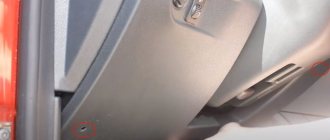
- Open the hood and remove the cover from the fuse and relay box. To do this, you need to press out 4 plastic latches;
- Move the rubber cover;
- Disconnect the upper block of the wiring harness from the block;
- We unscrew the 2 nuts that secure the block;
- We take out the block from the compartment, which is located in front of the windshield;
- We disconnect the lower blocks of the wiring harnesses from the block;
- Install fuses and relays in reverse order.
Repairing the mounting block involves replacing printed circuit boards. So, the algorithm for repairing the mounting block:
- Remove the mounting block;
- Remove the 8 screws that secure the bottom cover;
- Using a screwdriver, open the bottom cover;
- We check the condition of the tracks along which the current passes and the quality of soldering. If defects are detected, they must be eliminated, but if this is not possible, then completely replace the unit;
- Install the mounting block in reverse order.
This is interesting: Nissan Patrol configurations: technical specifications
Starter UAZ Electrical equipment UAZ
Starter 42.3708 (Fig. 261) or 4211.3708-01 with an electromagnetic traction relay and a lever drive with a roller freewheel clutch is installed on the left side of the engine (along the direction of the vehicle). The starter connection diagram is shown in Fig. 262.
Rice. 261. Starter 42.3708:
1-cover on the drive side; 2-lead ring; 3-thrust ring; 4-lock ring; 5-wheel drive; 6-anchor; 7-body; 8-brush; 9-traverse; 10-thrust washer; 11-adjusting washer; 12-lock washer; 13-cover from the collector side; 14-pin bolt; 15-pin plate; 16-relay cover; 17-return spring; 18-rod; 19-relay anchor; 20-compensating spring; 21-buffer spring; 22-gear; 23-screw M5x14; 24-nut tie rod; 25-screw M6x16; 26-nut M8; 27-relay coil input; 28-screw M6x30; 29-lever; 30-nut M8; 31-axis lever
Rice. 262. Starter connection diagram:
1-mass switch; 2-rechargeable battery; 3-additional starter relay; 4-ignition switch (lock); 5-voltmeter; 6-pin disk; 7-retractor winding; 8-holding winding; 9-traction starter relay; 10-starter
Periodically perform the following maintenance work on the starter:
- Check the condition of the clamps, making sure they are not dirty or loosened.
- Remove the protective casing and inspect the manifold, correct any faults if necessary.
- Open cover 13 (see Fig. 261) on the collector side, inspect and, if necessary, clean the contact surfaces, then blow with compressed air.
- If necessary, tighten the starter housing pinch bolts.
- Check the connection of the starter to the clutch housing.
- When operating the vehicle in difficult conditions, remove the starter to clean the drive and freewheel from dirt.
Every 32,000 km of the vehicle, perform the following maintenance work on the starter:
- Remove the starter from the engine.
- Check the condition of the commutator and brushes. Make sure that the brushes do not jam in the brush holders. If the brush height is less than 6 mm, replace them.
- Disassemble the starter. Replace worn parts.
- When assembling, lubricate the bearings and shaft journals with engine oil. Lightly lubricate the splined part of the shaft, drive offset bushings, fingers and the lever axis with Litol-24 grease.
UAZ starter: https://uaz.service-manual.company/elektrooborudovanie-uaz/starter-uaz/
Main faults of the UAZ-469 starter
What to do if the armature does not rotate when you turn on the starter.
| Probable cause of the malfunction | Remedy |
| Contact between brushes and commutator is broken | Remove the starter from the engine, disassemble it and eliminate the cause of the malfunction |
| There is no contact in the starter traction relay switch | Disconnect the wires from the starter, remove the switch cover with terminals. If the contacts are burnt, clean them. Rotate severely burnt contacts 180° around their axis |
| Broken connections inside the starter or in the traction relay | Repair the starter in a workshop |
| There is no reliable contact in the ignition switch at terminal “C” | Check the circuit using a test lamp connected to terminal C and ground. If there is no voltage at terminal “C” in the position corresponding to the starter turning on, replace the ignition switch |
| The winding is broken or the contacts in the additional relay are burnt | Check the circuit with a test lamp. The lamp connected to terminal “K” of the additional relay and ground should light up when the starter is turned on. If the lamp does not light, then disassemble the relay and clean the contacts |
| The armature is stuck in the sleeve of the electromagnet coil | Clean the armature, relay and bushing from dirt. If there is displacement of the traction relay relative to the starter lever, have it repaired in a workshop. |
What to do if, when the starter is turned on, the engine crankshaft does not rotate or rotates at a low speed.
| Probable cause of the malfunction | Remedy |
| Battery is discharged or faulty | Check the battery and replace if necessary |
| Short circuit of the armature or field coils or the armature touching the poles | Repair the short circuit or send the starter to a workshop for repair. |
| The engine crankshaft is difficult to turn | In winter, warm up the engine |
| The starter power supply circuit is broken due to loose wire ends | Inspect the entire starter power circuit, tighten all clamps |
| Severely worn bearings | Send the starter to a workshop for repair |
What to do if, when turned on, the starter shaft rotates at a high speed, but does not turn the engine crankshaft.
| Probable cause of the malfunction | Remedy |
| Broken flywheel teeth | Change the crown |
| Roller freewheel slips | Change the starter drive |
What should you do if, when you turn on the starter, you hear a repeated strong knock of the traction relay and the gear on the ring gear, but the engine crankshaft does not turn.
| Probable cause of the malfunction | Remedy |
| There is no reliable contact in the clamps, especially on the battery | Check and tighten clamp bolts |
| Battery is discharged or faulty | Check and charge the battery or replace it |
| The holding winding of the traction relay is faulty or its contact with ground is poor. | Replace the winding or ensure reliable winding contact |
UAZ Hunter UAZ 469. Fuses and relays
Location of the fuse box in the passenger compartment. . The unit is located under the instrument panel on the driver's side.
The relays are located under the instrument panel on the driver's side.
1 — relay for low beam headlights; 2 — relay for turning on the high beam headlights; 3 — relay for turning on fog lights; 4 — tailgate glass wiper relay; 5 — relay for turning on the rear fog lamp; 6 — windshield wiper relay; 7 - turn signal interrupter relay
The fuel injection system relay and fuse are located in the engine compartment.
Power fuses are located under the hood.
Power fuses protect the external lighting circuits and terminal 30 of the ignition switch.
Electrical diagrams of the fuse box UAZ Hunter, UAZ 469. Electrical equipment of cars modifications 315195-025, 315195-125
Electrical equipment of cars modifications 315195-023, 315195-123
1 — right front lamp; 2 — right headlight; 3 — left fog lamp; 4 — sound signal; 5 — right fog lamp; 6 — left headlight; 7 — left front lamp; 8 - generator; 9 — coolant temperature sensor; 10 — emergency oil pressure sensor; 11 — oil pressure sensor; 12 — emergency coolant temperature sensor; 13 — electric washer; 14 - switch for warning lamp for brake system malfunction; 15 — starter; 16 — battery; 17 — ground switch; 18, 19 — fuse block; 20 — starter relay; 21 — engine compartment lamp; 22 — power fuse block; 23 — fuse box lighting; 24 — side repeater; 25 — windshield wiper breaker; 26 — side repeater; 27 — fog lamp relay; 28 — brake light switch; 29 — heater electric motor; 30 — windshield wiper; 31 — heater resistance; 32, 33 — headlight switching relay; 34 — fog lamp relay; 35 — rear window washer time relay; 36 — instrument cluster; 37 — speedometer; 38 — block; 39 - engine fault warning light; 40 — control lamp for turning on the high beam headlights; 41 — indicator lamp for direction indicators; 42 — indicator lamp for turning on the parking brake; 43 - warning lamp for brake system malfunction; 44 — warning lamp for emergency oil pressure; 45 - warning lamp for emergency coolant temperature; 46 — battery discharge warning lamp; 47, 48 — indicator lamp for backup warning device; 49 — relay for direction indicators and hazard warning lights; 50 — parking brake warning lamp switch; 51 — heater mode switch; 52 — ignition switch (lock); 53 — ignition switch (lock) relay; 54 — light signaling switch; 55 — sound signal button; 56 — wiper switch; 57 — fuel level sensor switch; 58 — rear fog lamp switch; 59 — alarm switch; 60 — interior lamp; 61 — cigarette lighter; 62 — interior lamp switch; 63 — reverse light switch; 64 — fog lamp switch; 65 — external lighting switch; 66 — rheostat for instrument lighting; 67 — speed sensor; 68 — electric fuel pump with fuel level sensor; 69 — fuel level sensor; 70 — rear windshield wiper; 71 — rear window washer; 72, 78 — rear lamp; 73 — reversing lamp; 74, 76 — license plate light; 75 — additional brake signal lamp; 77 — rear fog lamp; 79 — air flow sensor; 80 — throttle position sensor; 81, 84 — temperature sensor; 82 — camshaft position sensor; 83, 85, 88, 92 — fuel injector; 86 — additional air regulator; 87 — knock sensor; 89, 90 — ignition coil; 91 — crankshaft position sensor; 93, 95 — automotive relay; 94 - fuse 10 A; 96 - fuse 20 A; 97 — diagnostic block; 98 — engine ECU; 99, 100, 101, 102 — spark plug; 103 — oxygen concentration sensor; 104 — adsorber purge valve
UAZ Hunter fuse diagram
The following description of electrical equipment is intended for models with petrol and diesel engines.
| Location | Decoding |
| 1 | Spare |
| 2 | Starboard clearance |
| 3/4 | Low and high beam head optics on the right side of the car. |
| 5 | Right fog light |
| 6 | For versions 2004-2006 - a portable socket and a tidy light. |
| 7 | Stop signals |
| 8 | Emergency crew |
| 9 | Klaxon |
| 10 | Illumination of the tidy, license plate light. |
| 11 | Cigarette lighter |
| 12 | Rear fog light. |
| 13 | Radio and head unit (if equipped) |
| 14 | Not used for the 2014 version. |
| 15 | Left gauge. |
| 16/17 | Low and high beam on the left side. |
| 18 | Left fog light. |
| 19 | Left side of reversing light |
| 20 | Turn signals |
| 21 | Stove fan. |
| 22 | Windshield cleaner and washer. |
| 23 | Interior lighting and engine compartment lamp. |
| 24 | Stock |
| 25 | Operation of instruments and warning lamps |
| 26 | Heater auxiliary pump. |
Next we should consider the relay module installed below the main panel.
| Arrangement order | Description |
| 1 | Low beam switch |
| 2 | Similarly for high beam head optics |
| 3 | Also for fog lights |
| 4 | Rear door glass cleaner. |
| 5 | Stern fog switch. |
| 6 | Windshield cleaner. |
| 7 | Turn breakers. |
Next in line is the main unit under the hood.
| Number | Purpose |
| Option 1 | |
| 1 | Outdoor optics |
| 2 | Ignition switch terminal 30 |
| Option 2 | |
| 1 | Ignition switch |
| 2 | External lighting devices |
| 3 | Fuel filter heater (not available on engine 406) |
| 4 | Glow plug power line. |
The last module is an auxiliary unit, mainly used on diesel engines.
| Number | Description |
| R1 | Starter relay switch. |
| R2 and 3 | Main relay 2 and 1 respectively. |
| R4 | Fuel heater |
| F1/2 | On-board network |
| F3 | Fuel heating |
| F4 | Diagnostic connector |
| F5 | Starter |
| F6 | Mass air flow sensor |
| F7 | Control block |
| F8-10 | Main relay |
Turns
There is only one fuse in the car. Due to the low power of the lamps, it is enough to connect them into a single line. For LED elements and their analogues, insert 20 is installed in the interior compartment. 4 x contact relay No. 7 is mounted under the main unit.
This arrangement of devices is relevant for cars up to 2016-2017 and older.
Cigarette lighter
The fuse on all Hunters, including 2013-2015, is installed in position 11. In the photo above, you can see the insert in its standard place.
Gasoline pump
The fuel pump power supply system is installed separately from the mounting blocks. The fuse is located under the dash. The relay is also mounted here. If the elements are constantly burning, you should check the integrity of the line.
Starter
The power line is turned on by switch R1. The control circuit runs from fuse F5. Both structural elements are installed in an auxiliary mounting block under the hood.
Speedometer
If the functional unit does not work, you should check fuse 25, installed in the passenger compartment under the instrument panel.
Inserts 3 and 16 are responsible for the lamps.
Ignition
The main relay of the system is connected to positions 2 and 3. The fuses are routed to inserts 8/10. All structural elements are installed in an additional module under the hood.
Wipers
The wiper fuse is installed at position 22 under the instrument panel. Switches 4/6, mounted nearby in the relay panel, are responsible for the power lines.
Dimensions
The power system has only two fuses. The elements are mounted at positions 2/15 and correspond to the left and right sides of the lamps.
Fuse 10, mounted in the cabin, is responsible for lighting.
Wiper
Powered by fuse 19. In some configurations there are no relay switches - their role is played by the steering column switch.
Charger
The system is designed in such a way that the limiting device is installed after the generator set. You can find it by its characteristic appearance and wiring suitable for the battery.
Reverse
The lamp switch is located on the side of the car. A corresponding fuse is also installed nearby, under the casing.
Generator
The installation voltage regulator is mounted classically - in the device body. To access the part, you will need to disassemble and remove the insert from the working shaft.
The switches are installed in positions 1 and 2 for the left and right sides of the car. In some versions, the relays are mounted on the headlight units.
Specialization: Graduated from the State Automobile University, worked for 20 years at GAZ-56, now I drive a Zhiguli.
Source of the article: https://rus-avtomir.ru/predohraniteli/rele-hunter
Engine compartment
For many years, the main power unit of the UAZ 469 was the in-line 4-cylinder UMZ-451MI carburetor type. The engine capacity was 2445 cc. cm, power – 75 hp.
With this engine produced by the Ufa Motor Plant, the UAZ 469 lasted on the factory assembly line until 1985.
It was distinguished by a simple single-wire 12-volt ignition circuit, which consisted of (according to the numbering):
- rechargeable battery (AB);
- mechanical ground switch;
- electronic battery charge voltage regulator;
- alternator;
- ammeter on the instrument panel;
- ignition switch (switch);
- ignition breaker contact group;
- directly to the ignition distributor (distributor);
- capacitor built into the distributor;
- ebonite distributor cover with leads for high-voltage wires;
- ignition distributor slider;
- spark plugs;
- high voltage wires from the ignition coil;
- additional coil resistance;
- starter relay;
- directly to the high-voltage ignition coil;
- electric starter.
New modifications of the legendary SUV received more modern engines and a modified electrical circuit.
In particular, the UAZ Patriot wiring diagram includes:
- electronic fuel injection system;
- contactless ignition system;
- climate control system inside the car;
- alarm system, etc.
Fuse box for SUV UAZ Simbir 3162, 31602
Designation in the picture:
- K2 - windshield wiper relay;
- K3 — direction indicator stick;
- K4 — electric relay for low-beam headlights;
- K5 — switch for turning on high-beam headlamps;
- K6 - additional (unloading) switch;
- K7 - solenoid for turning on the rear window heating;
- K8 - electromagnet for turning on fog lamps;
- A1-A23 - fuses (see table)
The power unit is installed in the car interior, on the left, under the instrument panel, opposite the driver’s seat.
Circuits protected by fuses:
| Designation | Current strength, A | Protected Circuits |
| Assembly electrical module | ||
| F1 | 5 | Instrument lighting, left side side lights |
| F2 | 7,5 | Low beam of the right electric headlight |
| F3 | 10 | Far illumination of the right lamp |
| F4 | 10 | Right fog light |
| F5 | 30 | Glass door lift system, electric sunroof drive |
| F6 | 15 | Portable lamp socket |
| F7 | 20 | Horn, electric mirrors |
| F8 | 20 | Rear window heating element |
| F9 | 20 | Glass cleaners and washers |
| F10 | 20 | Reel for headlamp cleaners |
| F11 | 5 | Side lights, right side, license plate light |
| F12 | 7,5 | Near left headlamp |
| F13 | 10 | Left high-beam light and high-beam indicator |
| F14 | 10 | Left fog light |
| F15 | 20 | Door lock system |
| F16 | 10 | Hazard warning and direction indicators |
| F17 | 7,5 | Courtesy lights, engine compartment lamp, brake light switch |
| F18 | 25 | Heater, cigarette lighter, rear window defroster switch |
| F19 | 10 | Instrument cluster, reverse light switch, on-board control system |
| F20 | 7,5 | Rear fog |
| F21 | 10 | Backup electrical fuse |
| F22 | 20 | Spare electrical plug |
| F23 | 30 | Emergency traffic jam |
The main relay 90.3747-10 (RF) is located on the front panel, above the engine, next to the fuel pump relay.
The fuel pump solenoid type 90.3747-10 (RF) is installed on the bulkhead, above the engine, next to the main electromagnet KMPSUD and the intermediate starter switch (retractor solenoid).
The intermediate starter relay is installed on the front panel, above the engine, next to the main relay KMPSUD and the fuel pump relay.
The main solenoid circuit coming from the battery is protected from short circuits to ground by a 20 A harness fuse type 688670-7 (AMP) or 354.3722 (RF). At the same time, the KMPSUD ignition circuit is protected from short circuits to ground by a 10 A harness fusible plug of type 688670-5 (AMP) or 352.3722 (RF). The plugs are placed in blocks that are attached:
- — 20A — to the main relay;
- — 10A — to the electric fuel pump relay.
What is included in the electrical circuit
The above is a form of electrical wiring diagram.
Regardless of which UAZ you use - old or new model - the main components of the electrical network are as follows:
- Dashboard. It displays the main sensors and indicators indicating that a particular device is turned on. Tidying allows the driver to know at what speed he is moving, how much fuel is left in the tank, what the crankshaft speed is and what the engine temperature is. In addition, there are many lights installed on the tidy that light up synchronously with the switching on of certain devices.
- Accumulator battery. The battery is an integral element of any car; it allows you to power the vehicle’s equipment when the engine is turned off, and also helps the ignition system in starting the power unit. If the battery is discharged, you will not be able to start the engine in the traditional way - you will either need to recharge it or try to start it with a pusher.
- A generating device, the failure of which will also make it impossible to start the engine. This unit provides voltage to all devices and devices used in the car while driving.
- Fuse block. This device contains all the safety devices designed to protect electrical circuits and devices from overvoltage. If there is a power surge in the network, then the main blow will be taken by the fuse (author - Ben & Ice Video Master channel).
Replacing fuses
If a blown fuse is found in the mounting block of the UAZ Hunter, then before replacing it you should figure out why this happened, find out all the possible causes of the breakdown and try to eliminate it.
Important! When replacing a faulty fuse-link with a new one, you must not use a metal tool (tweezers), which is a conductor of electric current. For personal safety, it is better to use plastic tweezers to remove and install the part.
It is prohibited when carrying out work:
- use inserts made by hand (with your own hands);
- install products that are not structurally provided for in this mounting block;
- use fuse links if their rated current differs from that indicated in the accompanying technical documentation for the vehicle;
- check the integrity of the electrical wiring (for the presence of a spark) by shorting it to the car frame.