Why do you need to install a relay in a car? Let's start with the definition:
Relay is an electrical device (switch) designed to close and open various sections of electrical circuits for given changes in electrical or non-electrical input quantities. Types of relays may differ in the control signal and in design, we will not dwell on this, especially since all this is on the same Wikipedia. We only note that electric (electromagnetic) relays are most widespread.
It is difficult to understand why a relay is needed from the definition, so let’s break it down in simple words: The relay is designed for switching large load currents. In other words, it is a switch, or even simpler - the principle of operation of a relay - with a small current (for example, a button signal) to turn on circuits with a large current. And a relay is used when the actuator (starter, generator, fan, heated mirrors, horn, etc.) consumes more current (up to 30-40 amperes).
FOR EXAMPLE: In order to start the engine with a small button, it is necessary to turn on the starter, which consumes from 80 to 300 amperes. If you do not use a relay, then the button will not withstand high current and will melt, as well as the wiring, which is not intended for high currents. Therefore, a connection is made through a relay (a relay is installed between the button and the starter), which, based on a small current impulse from the button, closes powerful contacts within itself, thereby turning on the starter. How does this happen ? **************************************** **************************************** ******************* Relay device
An electromagnetic relay consists of: an electromagnet (an electric wire wound on a coil with a core of magnetic material). armatures (a plate made of magnetic material that controls contacts through a pusher). switches (can be making, breaking, switching).
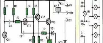
Relay Contacts: Pins 85 and 86 are the coil. Contact 30 is a common contact, always present in the relay. Without supplying voltage to the winding contacts, it is permanently closed to contact 87a. Contact 87A is a normally closed contact. Contact 87 is a normally open contact. Power contacts are always marked 30, 87 and 87a.
Every small car enthusiast knows that there are some kind of relays and fuses in a car. After all, in the event of an electrical fault in a car, the first thing to check is the relay and fuse box! So what is special about these relays, how do they work and what is their essence? Are they really necessary and irreplaceable? I will talk about this in the article. Since they, that is, relays, are in the car, then for some reason they are needed. And it was with the purpose of the relay in the car that I wanted to start. Relays have several tasks and functions.
Why do you need a relay in a car?
First, and most importantly, is the ability to control power currents for power loads. That is, when the input signal to the relay is literally several mA, we already get several tens of Amperes at the output. No, the relay does not amplify the signal, it only switches currents, more on this later when it comes to the principle of operation. Secondly, the relay can functionally switch the load between 2 or more different electrical circuits, while doing this from 1 control signal. That is, at the input we again have 1 input voltage of several mA, and the power contacts switch among themselves for different circuits. Let's say the low beam headlights were working, and the high beam headlights turned on. Third, the relay, due to its audible response signal, makes it possible with a high degree of probability to diagnose its correct operation and, as a consequence, the operation of the supply circuit. That is, if there is a signal, then most likely there is also voltage in the supply circuit. If there is no click, then you should check the fuse! Also, the sound of the relay when the turn signals are turned on indicates that they are most likely working, which is important when changing lanes. And if the turn signal lights up frequently, they indicate a burnt-out lamp. Fourth, this is a consequence... By controlling power signals, they can save on copper wiring in the car, since the relay unit is most often installed in the engine compartment, closer to the power control circuits. That is, thin copper wires go to it, from the controls in the cabin, and thick copper wires go out to the power loads in the engine compartment. (headlights, ignition switch relay, diesel heaters...)
Other less popular methods
Many people are interested in how to connect DRLs without a relay on their own, but it depends on the electrical system of your car; look for a solution in online clubs dedicated to your car. The most important thing is that power is supplied to this place after the engine starts.
The basic diagram for connecting the DRLs is through a 4 or 5 contact relay, which turns off when the low one is turned on. Those who are not too lazy to rummage through the car’s wiring can connect it from the oil pressure sensor or generator. On any vehicle, when the engine starts, the oil pressure light on the dashboard lights up, the signal from this wire is used to supply power. The second way to connect running lights yourself is to connect to a generator. They will turn on automatically when voltage appears on the generator.
How does a car relay work (four- and five-pin)
The relay is one of the first radioelements that people invented! Ever since Faraday discovered the features of self-induction current in 1831, that is, he found out that the current in a conductor creates an electromagnetic field capable of attracting magnetizable materials, it was from that time that there were all the prerequisites for someone to take advantage of this and create relay! Actually, this was created around the same time, and was mentioned for the first time in the patent of Morse, the same one who invented the telegraph (1838). And now we, in the footsteps of the greats, will understand the operation of a car relay, which is not very different from what was invented in the century before last. So, there is a coil wound on a core. When current passes through a wire, an electric field is formed in it. Due to the large number of wires wound in one direction, the electric field is added up and intensified. This field is capable of attracting magnetizable material, but as you understand, only while the current is flowing in the conductors, that is, in the coil. And now the current flows, a magnetic field is created, a group of contacts attracted by this field is triggered... Now it’s time to turn to the illustration.
Again. As soon as an electromagnetic field is created, it attracts the actuator associated with the contacts. As a result, they close or open. This is how the switching of power circuits occurs, which I spoke about earlier. Here the imagination of relay designers or common sense pragmatism will dictate how many contacts we need to switch in a given case. Hence the relay can turn out to be four-contact, where 2 contacts are the power supply to the coil and 2 are those that are switched. 5 contact, when 2 contacts are for powering the coil and 3 for switching between each other. And similar variations...
DRL controller
I prefer the DRL connection diagram using a control unit, the most reliable method, suitable for any car and does not require any knowledge. Many car enthusiasts buy a DRL control unit from AliExpress - it is inexpensive, and the reviews seem to be good. However, most reviews are left either upon receipt of the product or after several days of use. In fact, absolutely all DRL controllers from AliExpress are short-lived and have the following disadvantages:
- the operating principle does not comply with GOST;
- there is no stabilization (for the majority);
- low quality of materials and workmanship;
- the features of the vehicle’s on-board network are not taken into account;
- no guarantee;
- some do not have moisture protection.
Among the high-quality options, I can highlight the DayLight+ DRL control unit from a Russian manufacturer, which fully complies with GOST and is of good quality. The DayLight+ controller also has built-in stabilization, which will significantly increase the life of the running lights.
Designation of a car relay on the diagram, how to connect
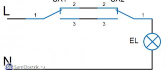
After everything has been clarified with the principle of operation, you can move on to formalities. Also, how is a relay indicated on a diagram or how to sketch it when creating such diagrams. The relay in the diagram is designated as a coil; it is a rectangle with two terminals and a separate group of contacts. That is, we draw as many contacts on the diagram. Here the diagram describes not only the number of contacts, but also their position. For relays, it can be normally closed (NC) or normally open (NO). If, in the absence of voltage on the relay coil, the contacts are open, then the relay is normally open...
Often the connection diagram is right on the body of the relay itself. At the same time, there are generally accepted standards. 85, 86 - terminals are the power supply to the coil, while 85 is connected to “+”.
In most cases, changing the connection between 85 and 86 contacts is not fundamental, but if the relay is protected against induction current and has a diode, then 85 is only positive, otherwise there will be a short circuit.
30 is a contact for the incoming power signal and 87, 87a are outgoing switched power contacts.
* - typical relay connection diagram.
Types of connection
DRL Eagle eye, eagle eye
The connection diagram for running lights depends on the configuration and your budget. There are 3 types of configuration:
- the most inexpensive, only DRL;
- average in price, stabilizer included;
- expensive, with a control controller.
If you have the cheapest and worst ones, then the kit does not include a controller or control unit. Such a unit performs the function of a voltage stabilizer and on/off control.
The average configuration includes a 12V voltage stabilizer. There are voltage surges in the car network, and LEDs really don’t like this and fail. The stabilizer will significantly extend the life of the LEDs. But in this option, you will have to choose a place for connection so that they turn on only when the engine is running. There are many places for this, for example an oil pressure sensor or a generator.
Domestic model
The expensive version is equipped with a control unit that connects directly to the battery in the car. According to the principle of operation, they are of two types:
- determine the difference between the number of volts when the engine is off and on;
- cheaper, it turns on when the voltage rises above 13V.
The best option is the first one, regardless of the voltage on your battery, always turn it on and off correctly. The second option is budgetary and does not always work. With the engine off, the number of volts must drop below 13V for the controller to turn off the DRL. However, if your battery is new or well charged, then even after stopping the engine, it will have a voltage above 13V for up to several hours. That is, the daytime running lights will not turn off on their own until there is less than 13V. The only drawback will be its own power consumption when the controller is waiting for the engine to start. It will drain the battery along with the security alarm.
Characteristics of automotive relay
Since the relay is designed to work with high currents, one of the important characteristics is the current with which it can work. That is, there are markings 20A, 30 A, 40 A and more. It is necessary to pay attention to this indicator when selecting a relay for a load of known power. After all, such large currents with an on-board voltage of 12 volts actually do not produce such a large total power. That is, if we have 55 W lamps on the headlights, then the total is 110 W. Using the formula P=U*I, the current is 110:12=9.1 A. As a result, it turns out that one relay can simultaneously switch 2 groups of headlights, no more. If this is a whole “chandelier”, then we select the relay current based on the load power, using the formula above... An example is given.
Opening the trunk using the car alarm key fob
If your car has an electric trunk drive, you can connect to it with a car alarm to open it using the alarm key fob. If the alarm outputs a low-current signal to open the trunk (and most often this is the case), then we use this circuit.
First of all, we find the wire to the trunk drive, where +12 Volt appears when the trunk is opened. Let's cut this wire. We hook up the end of the cut wire that goes to the drive to pin 30. We hook up the other end of the wire to pin 87A. We connect the alarm output to contact 86. We connect contacts 87 and 85 to +12 Volts.
Now, when a signal is sent from the alarm to open the trunk, the relay will work and “plus” will go to the trunk electric drive wire. The drive will operate and the trunk will open.
How to check the operation of a car relay
It remains to mention how to check the relay.
The simplest thing, as I already mentioned, is to hear the sound of operation. If it is, then the relay most likely has nothing to do with your malfunction. However, the “words most likely” are most likely not accidental here. The relay contacts may completely burn out, and as a result the relay will stop switching the circuits, that is, performing its main tasks. You can check the absence of resistance like never before using a trivial multimeter. We set the resistance to continuity and check. There are several Ohms on the coil, and even less than 0-1 Ohms on the group of contacts. Actually, now you know much more than before you started reading this article, all that remains is to repeat everything again in the video. This question sooner or later arises for almost all car owners. These little black boxes, scattered throughout the car, do something inside themselves, click, tick and sometimes break. What is a relay?
In general, relays are different. There are a huge number of relays, divided by type of operation, voltage, scope of application, and so on. But in this article, we will deal with conventional electromechanical relays that are used in any cars that you see around.
What is a relay?
A relay is a device that allows you to close or open an electrical circuit based on a specific signal. In the classic version, such a signal is a regular voltage, but applied to separate contacts. Why is this necessary?
Relays are used, firstly, so that powerful consumers of electricity can be controlled using weak control elements. Secondly, the relay makes it possible to turn on several consumers with one button.
Real life example: ordinary car headlights. Halogen headlight bulbs typically have a power rating of 55 watts. There are two of them, which means that the total power is already 110 watts. When you press a button in the cabin or turn the headlight switch, the light bulbs in the headlights light up and create a load in the wires just for these 110 watts. This power is not small, and without a relay all of it would pass through the switch. In order to implement this, it would be necessary to run thick wires into the interior, and the switch itself would be powerful and most likely ugly. It would hardly be possible to place it in the steering column switch (as, for example, on Japanese cars).
If we take into account that there are a lot of powerful consumers even in classic Zhiguli cars ( cooling fan , headlights, heated rear window, starter), then a huge number of thick wires would have to be installed into the cabin and powerful controls would have to be made.
The relay frees you from all this. To understand how it does this, let's look at its internal structure.
How does the relay work?
The basis of the relay is an electromagnet and a contact group. The contact group, in the simplest case, consists of four contacts. Two of them are power supply to the electromagnet, the rest are power supply to the consumer connected via a relay (for example, a heated rear window). These contacts have their own names - control circuit and power circuit (or control contacts and power contacts). Accordingly, the power circuit is powerful contacts that pass current through themselves to the consumer (for example, 110 Watts for headlights). The control circuit operates with a weak current and is designed to power an electromagnet. In this case, “plus” is applied to one (certain) contact of the electromagnet, and “ground” is applied to the second contact, that is, it is usually connected to the car body.
Powerful wires are connected to the power contacts, and it turns out that the relay, as it were, breaks these wires into two parts so that it is possible to control the current inside them.