01 December 2016 Lada.Online 83 820 7
All cars have a device for producing sound signals (horn), but its sound does not always suit the owner. This is the main reason for replacing the standard horn with alternative options (for example, with a sound signal from the Volga). Let's look at this improvement in detail.
Nowadays, horns are usually used in pairs. One with a high tone, the other with a low tone. This provides strength and beauty of sound.
Will need to buy:
- A couple of sound signals from GAZ 3110 (article number for high tone - 22.3721, for low tone - 221.3721), or an analogue, approximate price 500 rubles; Other sounds in this category.
- 4-pin relay 75.3777-10;
- Relay socket;
- Mounted fuse 10-15A;
- Single-core wire;
- Corrugation for wires;
- Terminals;
- Brackets/brackets for mounting sound signals (optional).
Installation and connection of a sound signal from the Volga is shown using the example of the Lada Vesta sedan. On other cars (for example, Lada Largus, Granta, Kalina, Priora, Niva 2121 or XRAY) all actions are performed in a similar way.
How to replace the sound signal on a VAZ 2170-VAZ 2172?
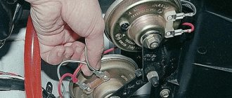
1. First, disconnect the block of wires from it, as shown in the large photo (Only in the large photo the block is removed and one terminal is left, but yours will be slightly different), then unscrew the nut that secures the bracket coming from the sound signal and remove everything this is assembled, by the way, when the block is disconnected, look at its contacts as well as at the terminal where this block is connected, they should be clean and free of signs of corrosion and oxidation, if necessary, clean it all with fine-grained sandpaper and try to reconnect the wiring block into its place and press the sound signal; if nothing changes, then the signal must be adjusted.
2. To adjust the signal, you need to hold it in a vice (by the bracket coming from it) or secure it anywhere, take two wires with the ends exposed and draw the plus from the battery to the plus of the sound signal, and the minus from the battery to the minus of the sound signal signal as shown in photo 1, the signal should start working, take a screwdriver, slowly turn the adjusting screw, make sure that the signal works loudly and clearly (see photo 2), if necessary, replace the sound signal with a new one.
Note! If you have some other signal installed and you don’t know where the minus is on it and where the plus is, in this case, use a special screwdriver with which you can find where the plus is, it works according to the following principle, put the terminal back on the battery (If it was previously reset) and when the screwdriver is brought to the terminals of the connector, when it lights up, this will indicate that this terminal goes to the plus, check the block of wires that comes from the sound signal and you will immediately understand where the plus is and where the minus is!
3. A new signal is installed in the reverse order of removal, when it is secured, a block of wires is connected to it and it is then checked for functionality; if the signal for some reason does not work, then perhaps the problem is not in it but in the wiring.
Additional video: How to get to the signal and how to remove it is shown in detail in the video below; in addition, it also shows the process of installing four signals from the Volga, which will be useful for absolutely any car.
Lada Priora Hatchback “Priorka” › Logbook › Long ago and banal: signals from the Volga.
. In the second month after buying the car. Ideally, each signal should be attached to a strip of springy steel, then it will be even louder. But there is not much space in front of the radiator. Initially, I didn’t want to place signals, as many do, on the right and left behind the bumper, on the right and left of the side members. It is not right. Sound waves should have no obstacles in their path.
I installed Volgov ones. I had to slightly file the plastic of the horns on the side of the A/C radiator, otherwise they were very close. All power wires are 4mm2 (four squares) and of minimum length, laid in corrugations. Soldering everywhere, no crimping. A wire with a closed adapter for a 20A blade fuse comes from the positive terminal of the battery. I used closed terminals (in housings) and filled them with graphite (or Litol, I don’t remember) to reduce oxidation.
I also coated the signal studs and nuts generously with graphite.
Additional relay on the washer reservoir mounting stud. Directly from the stud, I took the ground through the terminal for the relay winding (pin 85). The 86th contact of the relay was connected with a wire to the standard signal connector.
Closed adapter for a 20A blade fuse near the positive terminal of the battery (hid behind the battery):
So these signals worked for almost 7 years. In the winter of 2017-2018, one tone began to fail, and then stopped working altogether. And a year ago I replaced them with a new set.
6 years ago signals from the Volga were installed. Original (Lyskovo). I took them off my broken 9 before selling it (probably a bad omen in vain. The Priora was beaten many times later...). So these signals are from 2010.
At the end of last year they started to glitch. And the signal volume was no longer the same. At the beginning of January of this year, one signal simply failed (high tone) and subsequently worked spontaneously.
Relay and fuse blocks
The VAZ-2170 has three relay and fuse blocks:
- main block;
- mounting block;
- additional mounting block.
Luxury "Priors" with air conditioning have another additional block in which relays and fuses are located that are responsible for the operation of climate control equipment.
Main power fuse block
The main unit is located in the engine compartment of the car next to the battery and expansion tank. It is protected from above by a removable plastic casing. The main unit contains only six fuses that are responsible for the operation of the main (power) electrical circuits of the car.
To replace the fuses in the main unit, you need to disconnect the ground on the battery, remove the cover and replace the faulty part. VAZ-2170 mounting block
Relays and fuses in the cabin
The mounting block is located in the car interior under the dashboard on its left side. It is protected by a removable plastic panel attached to the “torpedo” using three latches. To remove the panel you need to turn each of these latches 900 degrees. After this, the panel will be completely removed.
The location, number, and markings of relays and fuses in the Priora mounting blocks may differ depending on the type of vehicle equipment.
Mounting block fuses
To remove the mounting block from its seat, you only need a screwdriver with a Phillips bit. She needs to unscrew the screw securing the block, then, pulling it towards you, disengage it from the fastening hooks.
Before replacing relays and fuses, you must disconnect the negative terminal from the battery. To remove the main unit, you will need to disconnect all terminals with wires connected to it, having previously marked their location.
Additional mounting block
The additional VAZ-2170 mounting block is located behind the panel of the right tunnel trim on the left leg side of the front passenger. To get to it, you need to unscrew the screws securing the cladding and remove it.
The additional mounting block contains three fuses and two relays.
To replace fuses and relays in the additional unit, there is no need to remove it from its mounting location. To remove the relay, you should unscrew the corresponding nut securing it with an “8” wrench. Before carrying out work to replace the relay, fuses or the entire unit, it is strongly recommended to disconnect the ground wire from the battery, and also disconnect the wiring harness block of the electronic engine controller from the additional connector mounting block.
Control and protection unit for climate control devices
In “Priors” equipped with climate control equipment, another additional mounting block is installed. It is located next to the main unit, and is attached to the “glass” of the left rack. Depending on the manufacturer of the climate system, the relays and fuses in it may have different locations and purposes.
Replacing the Priora comfort unit
Before purchasing a new product, you must be sure that the cause of the malfunction lies precisely in it. To do this, you can install a known-good unit in your car and test the operation of problematic units. If, with a new, serviceable device, electrical consumers operate normally, the old comfort unit is faulty. Otherwise, use an integrated approach, check fuses, relays, wiring, and all kinds of drives. In other words, the entire technical chain with which the faulty unit usually comes into contact during operation.
Replacement of the device is carried out in 7 simple steps:
- We put the car on the parking brake.
- Open the hood, loosen the negative terminal and remove it from the battery.
- We move into the car interior. For ease of operation, we roll the front seats back into the cabin as far as possible.
- We prepare the tool. Using a screwdriver, unscrew the mounting bolts and remove the 2 side walls.
- Using a 10mm wrench, unscrew the two fastening nuts.
- Carefully remove the block itself. When removing, rotate the product so that it does not hit other elements. Disconnect two contact connectors, the first is power, the second is information.
- Remove the faulty product and install a new one.
In the future, in order to inspect, diagnose or repair the Priora comfort unit, you will need to remove its protective housing. When purchasing a new unit, keep your sales or sales receipt. If you purchase a faulty device, this will allow you to return or exchange it for a new one. Prices for the product vary depending on the specific seller and range from 2,500 rubles to 10,000 rubles.
Instructions for installing Volgov signals on a Priora.
To install signals you will need:
the signals themselves (2 pcs.) copper wire with a cross-section of 2.5 mm2 and a length of 1.5 m a soldering iron (if you solder the joints) or electrical tape (if you connect the wires by twisting) a figured screwdriver a knife a “14” wrench
| First you need to remove the radiator grille, unscrew 6 screws. | |
| Carefully pull the grill towards you... | |
| ...and we try not to lose the fastening plates into which the screws were screwed in | |
| We remove the standard signal | |
| Checking the plus on the connection connector | |
| I myself made a male connector for connecting Volgov signals to the specified connector | |
| We are attaching new Volga signals. We connect the “pluses” to each other, and connect one “plus” to the power connector. The “minus” will be the weight of the car | |
| This is what installed Volgov signals look like |
Source
Tags: installation of Volgov signals on a Priora, independent replacement of standard signals with Volgov signals on a Priora
Maintenance and testing of the VAZ generator
Generator Maintenance
- in cleaning external surfaces.
- in checking the fastenings of the generator to the engine.
- in checking the reliability of wire connections with the generator and voltage regulator
- in checking the tension of the generator drive belt (if the tension is weak, the generator will operate unstably; if it is strong, the belt and bearings will wear out quickly). The check should be carried out every 10 thousand km. mileage
- in checking the condition of the generator belt (there should be no cracks or delaminations on it).
- in checking the condition of the generator bearings (remove the belt and rotate the generator rotor by hand; if jamming, play, noise or clicks are observed, the bearings should be replaced).
How to install a Volgov signal on a Priora
According to fashion, everyone started installing Volgov signals on their priors. Considering this not a show-off, but a real contribution to security, I began to surf the Internet in search of the necessary information on the location and method of installation.
First I bought signals for 410 rubles (for both). In the store they were still for 890. And the saleswoman even suggested that I listen to them - for 890 they sound very low like a locomotive, and they are expensive.
The Prior has 2 beeps, but only one works as a signal. A block with a plus and a minus fits it. But on Volgov signals you only need a plus, since the housing is a minus.
In general, on the Internet I dug up 2 installation methods: directly
to the standard wire (plus): the block is cut off, the minus is insulated, or through a relay
.
Although the Priora has a K8 relay, which is responsible for the sound signal, I still chose the second installation method, although it is more complicated.
Regarding the installation location: people have at least 10 options. For example: on the arch on the timing side, in the place of the standard signal near the hood lock, behind the bumper on the sides under the headlights, behind the bumper where the beam is and even on the sides of the air filter.
At first I wanted to install them on the arch, since there are factory bolts welded there for weight, but I changed my mind and ended up installing them in place of the standard one near the hood lock. No need to remove the bumper, no need for a soldering iron either.
, I did not disconnect the ground either, since it is open on the steering wheel.
So, gentlemen, what do you need?
: 1. Signal from the Volga - 2 pcs. (410 RUR) 2. Relay 4-pin 30 A with an ear for mounting - 1 pc. (75 RUR) 3. Copper wire with a cross-section of 2.5 square meters. mm - about 25 cm. 4. Connecting block with 4 wires for the relay - 1 pc. (20 r.) 5. Coupling for connecting steering rods from Lada cars - 1 pc. (60 rubles). I took 2 plates from it as brackets. I had to sharpen them a little with sandpaper and straighten them with a hammer, but they fit perfectly and are not flimsy at all. 6. Female terminal 6.3 mm - 2 pcs. (8 rubles) 7. Connector for connecting blue and red wires - 2 pcs. (20 r.) 8. Male terminal 2.8 mm - 2 pcs. (4 rubles) 9. Male terminal 6.3 mm with one wire - 2 pcs. (8 rubles). For extending wires from the block. 10. Plastic clamps - 2 pcs. (1 rub.) 11. Electrical tape.
Lada Priora Hatchback “Priorka” › Logbook › Long ago and banal: signals from the Volga.
. In the second month after buying the car. Ideally, each signal should be attached to a strip of springy steel, then it will be even louder. But there is not much space in front of the radiator. Initially, I didn’t want to place signals, as many do, on the right and left behind the bumper, on the right and left of the side members. It is not right. Sound waves should have no obstacles in their path.
I installed Volgov ones. I had to slightly file the plastic of the horns on the side of the A/C radiator, otherwise they were very close. All power wires are 4mm2 (four squares) and of minimum length, laid in corrugations. Soldering everywhere, no crimping. A wire with a closed adapter for a 20A blade fuse comes from the positive terminal of the battery. I used closed terminals (in housings) and filled them with graphite (or Litol, I don’t remember) to reduce oxidation.
I also coated the signal studs and nuts generously with graphite.
Additional relay on the washer reservoir mounting stud. Directly from the stud, I took the ground through the terminal for the relay winding (pin 85). The 86th contact of the relay was connected with a wire to the standard signal connector.
Closed adapter for a 20A blade fuse near the positive terminal of the battery (hid behind the battery):
So these signals worked for almost 7 years. In the winter of 2017-2018, one tone began to fail, and then stopped working altogether. And a year ago I replaced them with a new set.
6 years ago signals from the Volga were installed. Original (Lyskovo). I took them off my broken 9 before selling it (probably a bad omen in vain. The Priora was beaten many times later...). So these signals are from 2010.
At the end of last year they started to glitch. And the signal volume was no longer the same. At the beginning of January of this year, one signal simply failed (high tone) and subsequently worked spontaneously.
Turning off the standard radio of the Lada Priora when arming
I was puzzled, so how can I turn off the standard radio when arming. From the factory, the standard PG is powered directly from the battery and is never completely de-energized. This is not right. Therefore, before leaving the car, you should always turn off the power steering manually. Tired of it. People are solving this problem, no matter what. The most common scheme is diode isolation. I will not describe the meaning in detail here, because everything is on the Internet. I’ll just say that if diode isolation is used, after the ignition is turned off, the GU continues to work until you turn it off manually. Only after this is it de-energized and will not turn on again until the ignition is turned on. As I understand it, such a garden was fenced in to reduce the current consumption of the on-board network at rest. Looking ahead, I’ll say that after measuring the current consumption of a standard power unit in the off state, I received a value of 10 mA. Therefore, you shouldn’t even fool yourself with the current consumption of a standard PG when it’s turned off, because it consumes practically nothing. Thus, the use of diode isolation does not relieve us of the need to turn off the PG manually. I saw another way. People are making a hybrid ignition lock, that is, they add some details from the ignition switch 2110 to the prioro lock (there is a contact group that is closed while the key is simply inserted into the lock and opens if the key is pulled out). In this case, in order to listen to music in the car, it is necessary that the key is in the ignition even when the car is turned off. Rave. I decided that the mafon should only turn off when arming. In all other cases (whether the engine is started or turned off, the ignition is on or off, the key is in the ignition or not - it doesn’t matter) the mafon should work. I started to look into this issue and then an unpleasant surprise awaited me. It turns out that on Priors and on Kalinas there is nowhere a standard output that would change its state only when armed. For a couple of days I went through all sorts of options until I remembered that back in 2011 I installed a Master Priora glass closer. So, this closer has such an output, and the instructions say in black and white that this output, in fact, is intended to turn off the radio. This function was simply not used for me. While the car is not armed, +12V is present at this pin (blue). As soon as the system is armed using the remote control, 0V appears on this pin. Therefore, it is enough to install a relay that will be controlled by this signal and interrupt the power supply to the standard PG.
0:4669
1:504
All modifications are shown in red. The signal from the control blue wire is supplied to the relay coil. The second terminal of the winding is connected to ground. Thus, while the car is not armed, there is + 12V at the control blue terminal of the closer, which powers the relay winding and keeps it in the on state. The closed relay contacts, in turn, supply power to the standard control unit. As soon as the car is armed, 0V appears on the blue control pin. The relay turns off. Its contacts open and the standard control unit turns off.
1:1481
All that remains is to decide on the relyushka. Or rather, with its electrical parameters. The maximum load capacity of the control blue terminal of the closer is 100 mA. Therefore, the operating current of the relay winding must be less than this value. A standard GU when turned on and at almost maximum volume consumes no more than 4.5A. And at a volume of 12-13 units (at which I almost always listen), the current consumption is about 2-2.5 Amperes. This means that a regular low-current 12V relay is enough for me. I found similar relyushki in my stash. Size approximately 12 by 15 mm. The operating voltage of the winding is 12V. The operating current of the winding is 50 mA. Operating current through the contact group is up to 20A. Looking at the size of the relay, this figure is hard to believe. But it will definitely handle 10A. And 2 - 2.5A and even more so. I quickly made a printed circuit board and assembled a device consisting of one relay and 2 terminal blocks.
1:3077
2:504
3:1009
To make the dimensions of the device clear, I photographed it together with the car remote control. The device is quite small.
3:1222
Well, the scarf is installed on the car.
3:1290
4:1795
Everything works as it should. We armed the car using the remote control and the phone immediately turned off. If you sit inside the car and simply press the central locking button, locking all the doors, then the control unit continues to work. If you arm the car using a non-standard alarm, the GU will also turn off. And after disarming, power to the control unit will appear only after the driver’s door opens. Now I’ll think about how to make the GU turn on automatically immediately after disarming.
4:2704
https://www.drive2.ru/l/10516985/
4:36 next article:
Connecting a subwoofer to the standard radio of the Lada Priora
We got around to connecting the subwoofer. Which my sister gave me. I won't say it was easy. Difficulties with the manager
5:895
Rating 0.00 [0 Votes] 15699
Recommendations
Comments 35
It all depends on what load the standard wiring is designed for; if it is designed for a maximum of 5A, and a non-standard signal consumes 10A, then an additional one is installed. relay and additional wiring is installed. wiring to battery. Do not forget that the wire cross-section must be appropriate. I think 2.5mm will be enough. In any case, with a relay it won’t be worse than without it, so the conclusion is obvious =) And here is the diagram tuning-lada-2109.ru/wp-co…uploads/2012/01/shema.jpg
I recently set exactly the same signal as yours. There is both a compressor and a pipe under the grille. It’s terribly inconvenient to install and it’s scary to break off the grille. I installed it on standard wiring. I just cut off the terminal and bought terminals for the compressor at the store. I wrapped the wires and put heat shrink on top. I just changed the fuse and set it to 20 amps. And I already had the relay in the fuse block. Or should I have put something else there?
It's not the relay, it's the wires. Add. The relay is installed so as not to pull new wires from the signal into the interior.
Thanks everyone for the answers. I will do everything through the relay according to Feng Shui.
If you install it instead of the usual one, at first the fuse will simply burn, but then the wiring will burn out 100%!
Be sure to put the relay on additional power, it’s not difficult... plus you’ll sleep peacefully...
Put Volgovsky ones. Since the air compressor freezes in winter and at the right moment you are left without a signal. (Checked it on myself). But there are a lot of fakes from Volgov. Be sure to install a relay. (I speak like an electrician)
Volgovsky ones are standing. A friend of mine has one like this. My Volgovs are nothing compared to his pneumos. I want to leave both the Volgov and pneumatic ones connected via a relay from a button
I installed it on a Priora for a friend without a relay, instead of the standard signal it was just to protect it, it was on at first and then they set it to 25 and everything was fine for 4 months already.
Don't listen to the pioneers))) Bet wisely. Through a relay, there must be a fuse and new wiring, not the standard one. Post it separately, don’t be lazy. Mount it not low, in front of the radiator it is better. The tilt of the pipe is slightly downward. The compressor is as close as possible to the dude. Cut off the excess hose! Make it as short as possible.
Here is a specialist on this matter))) www.drive2.ru/r/mitsubishi/828018/ I speak as a “doctor”. I have three of these))))
Without problems and relays. Everything works, the flight has been normal for 2 years. The entry is in the blog.
I did it through a relay, but what to check, go to 2 wires and go straight to the battery, and listen, after that connect to the standard place, believe me, tell me, the result is interesting
Question for backfilling, who has already tested, etc., what will be louder than 2 pairs of Volgov or 1 pneumatic, but pneumatic with such a weak compressor as in the photo
pneumatic is better. I have Volgov cars now
Question for backfilling, who has already tested, etc., what will be louder than 2 pairs of Volgov or 1 pneumatic, but pneumatic with such a weak compressor as in the photo
How to choose
Having decided to replace a relay or fuse in a Priora, take full responsibility for their selection and purchase. Under no circumstances should you buy cheap parts of unknown quality and origin.
It is better to give preference to original products produced by VAZ. As a last resort, buy relays or fuses from one of the well-known companies, such as Bosh, Hella or Tesla.
Replacing the sound signal on a Lada Vesta is a simple procedure that any owner should be able to perform. After all, driving without a properly working horn is a priori unsafe, and taking a car to a service station due to such a breakdown is an unreasonably large amount of time. However, replacement in the event of a malfunction is not the only need. Many people are simply not satisfied with the volume or tone of the sound signal, and they replace the standard Vesta components with alternative ones. Therefore, both of these paths need to be considered in more detail.
Replacing the standard sound signal in case of breakdown
First you need to prepare the car for work by putting the parking brake on and turning off the ignition. Then you need to lift the hood and, armed with a “10” key, disconnect the negative terminal from the battery. Then you should dismantle the front bumper, which is best done with an assistant, so as not to damage the paintwork on the bumper itself and on the wings of Vesta.
Once this is completed, all that remains is to disconnect the plug with the wires from the signal horn. Then you can dismantle the signal itself, the bracket of which is attached to the body with one nut. For dismantling you will need an extension, a wrench and a 13mm socket.
Assembly is carried out in the reverse order - you need to secure the signal, inspect its operation, install the bumper with an assistant and tighten the terminal on the Vesta battery.
Tags: pipe, pneumatic signal
Comments 24
If the Priora has a Conder, it won’t fit in front of the radiator, because There are two of them! I installed them today, I looked for a place for 2 hours, I stuck the pipe on the right side of the air conditioner tube with clamps, through thermal insulation, a compressor under the bumper, you have to remove it for the sake of it, whoever says that it was removed, I don’t believe it, it takes 10 minutes to put it on - 20! but it’s blowing, damn it, it’s scary!
Between the PTF there seems to be a place for a pipe! You will have to remove the bumper, it is not difficult in general. All details in the bibliography. Photos are available.
Remove and install the bumper for 15 minutes. Without removal you will suffer, you will lose a lot more time, and your nerves...
between the radiator and the grille. You remove the grille, if I’m not mistaken, 4 self-tapping screws, and you get free access to the installation site.
Tomorrow I’ll be able to send you a photo of where the signal is located under the hood. There’s enough signal!
Later I’ll post a photo of where I installed it without removing the bumper and everything else)
Thanks, I'll try it this week.)
take off the bumper for 5 minutes, what a pain in bending it
I put it in front of the radiator! Behind the radiator grille! I didn’t remove the bumper! I bent it back and put it in place! (though it was warm in winter, it’s not worth it, the plastic is brittle!) I attached it to stainless steel plates, screwed it into the holes that were
I installed it in the same way in the fall when it was warm and it still works great, just install a stronger fuse right away, otherwise the standard ones burn out quickly
I've been driving the standard one for 2 years now))
Alternative options
In this case, the possibilities are limited solely by the imagination of the Vesta owner. Most often, sound signals from the Volga are installed on the Lada, since their sound is much louder. But there are other ways. The most common options for such “modernization” are:
- installation of signals from the Volga - in this case, different installation methods are possible (with connecting a relay in the cabin or under the hood)
- combined option;
— installation of other signals;
— installation of a signal with an integrated compressor;
— a combination of signal and high beam.
Installation of signals from Volga
It involves not only installing “shells” directly on Vesta, but also various options for connecting them. It is worth remembering that the sound signal from the Volga can be either old or new. However, they have no differences, except for a slight difference in tonality:
— sound signals Volga-3110 (22.3721/221.3721) – low and high tone;
- sound signals Volga, RAF S302/303D - low and high tone.
Sound pressure – 105-118 dB.
It is necessary to take into account that simply replacing the signals on Vesta will not work, because their current consumption is different. For Vesta this figure is 5A (passport data), although in reality it usually does not exceed 3.5A. Signals from the Volga consume 8A each, which gives a total of 16A. Therefore, for their installation it is necessary to use a 4-pin type relay. In particular, you can use relay 904.3747-10.
In addition, on Vesta, only one plug is supplied to the factory signal - “Plus” is permanent, since it supplies power to the fan, and “Minus” comes from the button on the steering wheel. Regarding the Volga signals, they only need “Plus”, because “Minus” goes directly through the metal mount to the body.
It is also necessary to take into account the dimensions of the sound signals - the Volgov ones are larger than the standard ones on Vesta. Therefore, installation in factory locations is excluded. In addition, it is not advisable to mount them directly to the body, as this will lead to vibration, and the sound of resonating metal will be mixed with the horn. So the best solution would be to use a bracket. The advantage of this option is its low cost - a set of “Volgov” signals will cost about 1,000 rubles.
Installation of relays in the interior of Lada Vesta
This is done directly in the fuse box. To carry out the work you will need the following components:
— sound signals from the Volga;
— 4-pin type relay;
— relay block;
- single-core wire;
— terminals – wide (6 units) and narrow (1 unit).
For installation, it is best to use the free space in the fuse box, to which the wires from the contact relay, which is responsible for activating the signal on the steering wheel, are transferred. In the place that has become vacant, a wire from relay contact “87” is placed. Next, you will need to remove the wire from the 13th contact block and insert it into the 13th connector “87” of the relay contact.
To supply “Plus”, you will need to feed the wire to relay contact “30” from connector “Ш5-6”, using a jumper of contact “86”. In this case, you will have to insulate the wire in red-white or black-white color, since “Plus” always goes to it.
This method has a number of advantages:
— location of wiring under the hood;
— installation of the relay in the appropriate block, which guarantees dryness;
— use of a separate “Plus”.
However, if you have a complete lack of experience and knowledge in the field of car electrics, it is better to contact an auto electrician when installing a relay in the cabin.
Installation of a relay under the hood of Lada Vesta
Regarding the components, they are similar, but the list will need to be supplemented with a few more elements:
— terminals – 8 units;
— pendant type fuse;
- plastic corrugation - 2 meters.
The installation of the beeps themselves is carried out in a convenient place, and the connection is made according to one of two schemes:
- Using “Plus” directly from the fuse block;
- Using “Plus” directly from the battery, using a separate fuse.
In general, the second option is preferable. The relay should be located in a place protected from moisture. In addition, it is recommended to first wrap this component in polyethylene or insulate it.
The work is quite simple - you will need to dismantle the Vesta bumper and remove the factory signal, and then you can begin assembly. First, it is necessary to properly insulate the wires, and it is recommended to pass the wire that connects the signals through the corrugation so that it does not fray over time. Then you will need to fix the relay, after which you can put everything back together.
Combined option
This method involves retaining the standard Vesta beeps, but installing “Volgov” ones as additional ones. At the same time, combining 2 different tonalities will be a very original and specific move. Fixation is carried out in the same way as in previous cases, in any convenient place through a bracket. After which you will need to properly insulate all connections so that dirt and moisture do not get on them.
Installation of other sound signals on Lada Vesta
It is not necessary to concentrate exclusively on “Volgov” signals, since you can use beeps from other manufacturers. There are a lot of options on the market from different brands that you can buy - MITSUBA HOS-04GL, Elephant CA-10100 12v, GMP France / 410-510Hz and others.
Their price varies from 3,000 to 10,000 rubles, although there are sets up to 28,000 rubles. Their installation is similar to the processes with signals from Volga.
Installing a sound signal with a compressor on Lada Vesta
To fix it, you need a whole set of components:
— receiver – for compressed air;
- compressor - for pumping air into the receiver;
- pipes (signals) - compressed air from the receiver is supplied to them.
The undoubted advantage of this type of signal is its power, which significantly exceeds that of Vesta’s standard beeps. The sound of some signals can be heard 1.5-2 km away! Installation and connection are simple, and largely repeat the procedures with conventional signals, except that all elements will need to be connected to each other.
However, this type of signal for Vesta also has a number of disadvantages:
Price – the cost of such kits is noticeably higher than regular ones. The average price tag for a high-quality signal starts from 30,000 rubles. and reaches 40,000 rubles. There are many options for similar products on the market. For example, Hadley KIT 964 (29,500 rubles), Hadley KIT 984 (40,000 rubles), etc. Of course, you can also purchase a budget product, which is much more affordable, but its durability is questionable, in addition, the sound is quite fast such a signal fades out and becomes indistinguishable from the regular signal on Vesta.
Need for maintenance - this type needs to be lubricated and other measures taken from time to time.
Response time - unlike standard Vesta devices, which work immediately, beeps with a compressor are activated with a slight delay, since it takes time to fill the receiver with air. In a critical situation, these seconds can make a difference.
Installation location – the kit includes plastic elements, which are recommended to be installed at a distance from heating elements to avoid cracking.
Dust and dirt protection - it is necessary for the suction port of the compressor. To do this, you can use either a special filter or a regular stocking.
Crystallization of moisture - during operation of the pneumatic signal, moisture condenses on its working surfaces. Consequently, in winter, before warming up and thawing, the signal may simply not work.
The need to preserve Vesta’s standard signals is a prerequisite for successful maintenance.
Combination of sound signal and light on Lada Vesta
A very effective way to highlight a car is when, when you press the horn, the high beams will light up, or when you blink the high beams, the signal will also go off. However, when the high beam is turned on, the signal will not be activated. There is no need to change the basic wiring, just do everything according to the diagram.
More details about the Lada Vesta wiring, as well as connection diagrams, can be found in this file: shemy_chutov_provodov_lada_vesta
The car has two sound signals: in front, under the front bumper and under the front right fender. The first signal operates from a button on the steering wheel, and the second is the car's security alarm. Signals are removed for adjustment and replacement. Sound signals are interchangeable.
Recommendation
There is an adjusting screw on the horn housing, by rotating which you can adjust the sound of the signal.
It is more convenient to carry out the adjustment with an assistant who will press the horn button. If the sound is hoarse and weak, and it is not possible to achieve an acceptable sound by turning the adjusting screw, the horn must be replaced.
Removal
1. To remove the front signal, remove the front bumper.
2. Disconnect the wiring harness connector from the horn.
3. Using a 13 mm spanner, unscrew the nut securing the sound signal plate.
4. Remove the sound signal.
5. To remove the security alarm signal, disconnect the wiring harness block from it.
6. Using a 13 mm spanner, unscrew the nut securing the signal plate.
7. Remove the sound signal.
Installation
We set the sound signals in the reverse order.
How to check the generator on a car without removing it? Our review
- When the engine is running, the light that monitors the battery charge is either constantly on or blinking.
- The battery spontaneously discharges or boils away;
- The headlights shine dimmer than they should;
- The operation of the motor is accompanied by rattling or a low, continuous squeak. Alternatively, the generator may howl;
- As the engine speed increases, the brightness of the headlights increases sharply. This phenomenon is considered normal when revving at idle speed. However, once the headlights reach normal brightness, the intensity should no longer change. If you accelerate - they burn brighter, release the pedal - they dim, which means the generator is clearly unhealthy.
- The generator drive belt is inspected. The degree of tension is controlled; If delaminations, tears or cracks are detected, the belt is immediately replaced. In some situations, more complex actions are not required;
- The fuse is checked - like any other, it quite often fails;
- Next, you need to make sure that the rotor rotates freely, the wires are not pinched or frayed anywhere, the contacts have not come loose, and the housing is not cracked;
- The charging relay is replaced with a new one - this is the easiest way to make sure that everything is in order with it. In most cases, a visual inspection cannot give complete confidence in its performance.
- The engine starts. The meter remains connected to the battery;
- All the electrics on board start to work randomly: the heater turns on, the headlights turn on/off, more gas is periodically given, you can turn on the audio system;
- During the described executions, testimony is taken. If the voltage remains stable between 14 and 14.2 V, your difficulties are not caused by the generator. If jumps of no less than 0.5 V are noticed (and usually they reach 1 V), you have a direct path to a specialist who will find what has gone wrong in this node;
- Bearings can fail (it is they that cause the whine and whistling of the generator); the reason for the non-working condition can be clogged or worn out generator brushes, worn or again clogged rings.
AutoFlit.ru
Removing, installing and adjusting the sound signal of the VAZ 2170 Priora
- Repair manuals
- Repair manual for VAZ 2170 (Priora) 2004+.
- Removing, installing and adjusting the sound signal
Lada Priora cars are equipped with a sound signal of type 20.3721.
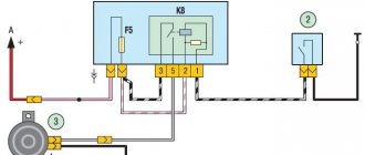
| . Scheme for switching on the sound signal: 1 – mounting block; 2 – sound signal switch; 3 – sound signal; A – to the main fuse block (F3); B – to the electronic anti-theft system control unit, terminal “20”; K8 – horn relay |
The circuit for switching on the sound signal is shown in.
If the sound of the signal becomes quieter or wheezing appears, you can try to adjust the signal with the adjusting screw.
You will need a key "13".
1. Remove the front bumper (see “Removing and installing the front bumper” ).
| 2. Disconnect the wiring harness connector from the horn. Check the signal contacts and wiring harness terminals. If they are oxidized, clean them. | 3. Unscrew the fastening nut and remove the horn and bracket assembly. |
4. If cleaning the contacts does not produce results, disconnect the wire from the negative terminal of the battery and the wiring harness block from the signal.
| 5. Clamp the signal by the bracket in a vice. Connect the wires to the battery and the horn contacts (“minus” to the top horn contact, “plus” to the bottom). | 6. Turn the adjusting screw (slowly) with a screwdriver until the signal sounds loud and clear. If this fails, replace the signal. |
The speed sensor is important for driving safety
On Priora, the reliability of the speed sensor is rated as average. Possible disadvantages:
If there is a problem with the speed sensor, the controller enters data with code “24” into RAM and lights a signal indicating the need to check the engine. If the car has problems with the engine idling, but the “Check Engine” signal does not come on, then the problem may be with another sensor (mass air flow). Checking the operation of the speed sensor begins with grounding on the third contact and supply voltage (12 V) on contact “1”. Pulse signals on the second contact are carried out at a speed of at least five kilometers per hour for the drive wheels. To study the state of the second contact, an oscilloscope or multimeter is usually used; for the first and third contacts, you can use the dialing technique.
