I was faced with the problem of turning on the turns for a long time, at first there is a delay of 1-1.5 s, after which the switching frequency is weak. I decided to change the relay and immediately connect the alarm system. After all, if anyone doesn’t know, the alarm system began to be installed on cars of the VAZ family starting with model 2103 , not including imported cars.
So, we will need: 1. Relay for turns and emergency lights from VAZ 2106. Number (781.3777) 2. Connector for the relay 3. Hazard warning button 2106, namely 6-pin. Number (245.3710) 4. Connector for button 5. Key for 10. 6. Electrical tape or heat shrink tubing. 7. Installation wire (about 5 meters). Preferably pieces of different colors.
We will need about 3 hours.
Work order:
You can also use an old relay by connecting it as in diagram 2106, but the original relay 2101 uses outdated technology and is very sensitive to load changes, so the process of replacing the relay is described below.
We remove the old turn signal relay by unscrewing the nut securing it to the front panel and disconnecting the three wires from it. (the colors of the wires must correspond to the colors in diagram 2101) In order not to lose the nut, immediately put a new relay in this place and lightly screw the nut on. (don't delay)
I hope that you have already decided where you will install the hazard warning button... If not, then decide quickly, because we are starting to lay the wires and pull them to where the hazard warning button will be. My button is located in the radio cover in the dashboard. (to the right of the steering wheel)
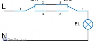
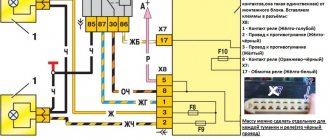
Relay contact 2 is connected to the wire removed from contact “L” of the old relay and to contact 7 of the hazard warning button. Relay contact 1 is connected to contact 4 of the hazard warning button. Relay contact 3 is connected to the wire removed from contact “P” of the old relay. We attach the wire from contact 4 to ground, under the relay mounting nut.
By the way, after all of the above has already been done, you can tighten the relay mounting nut. (don’t overdo it, the mount is plastic, it can break)
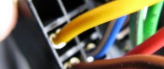
Button contact 4 should already be connected to relay contact 1. Contact button 2 is connected to the wire removed from the “+” contact of the old relay. Button contact 7 should already be connected to relay contact 2. We connect the contacts of button 1 with the steering column turn signal switch to a blue wire with a black marker. We connect the contacts of button 3 with the steering column turn signal switch to a blue wire.
Contact button 8 is connected to the positive, which does not depend on the position of the key in the ignition switch. You can use the plus from the cigarette lighter. If the plus is taken from the battery or from the generator, then it is advisable to protect this circuit with an 8A fuse. In my case it was to fuse No. 1, because it goes to the plus of the cigarette lighter.
That's the whole installation.
After this, we tighten the resulting braid of wires with clamps and secure the wires so that they do not dangle or fray. You can attach new conductors with electrical tape to existing braids.
All drivers are required to indicate maneuvers on the road by turning on the direction indicator. This flashing signal is found in every car. Its operating mode creates a turn relay, the circuit of which supplies current to the light bulbs and causes them to blink. At the same time, an audible signal sounds in the form of clicks, reminding you that the direction indicator is on. All these actions are provided by a special turn relay circuit.
Among various designs, electromagnetic-thermal and electronic relays are most widespread. The latest devices are considered more modern and are installed on all later car models.
How does an electromagnetic-thermal relay work?
These devices are no longer used in modern cars. However, in older models they are still widely used.
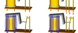
The design of the electromagnetic-thermal relay is quite simple; it uses a circuit for connecting turn signals through an electromagnetic-type relay. It is made in the form of a cylindrical core, and a thin copper wire is used as its winding. At the top of the core there are two groups of contacts, and metal anchors are installed on each side. The first group of contacts closes the circuit where there is a control light located on the instrument panel. With the help of other contacts, the circuit with the lamps in the direction indicators is closed. They are the ones who provide the flashing mode.
A thin nichrome string is attached to the anchor of the main group of contacts. It pulls the armature away from the contact, which is located on the core. Thus, the circuit will be open, which is its normal position. The core itself is installed on a special insulated platform, where the opposite end of the string is also fastened. During operation, an electric current passes through the string, since it, together with the resistor, is in the switch circuit. All elements of the device are housed in a cylindrical metal case.
The operating principle of an electromagnetic-thermal relay is very simple. When the turn signal is turned on, the circuit is completed. Under the influence of current, the nichrome string heats up and its length increases. The anchor, which was previously pulled back, is attracted by the core, straightens and closes the contacts for a short time. Because of this, the turn signal lamps begin to shine at full intensity. The current passes by the string, causing it to cool and shorten again. As a result, the armature is pulled away from the core, which leads to the opening of the contacts. The lamps stop shining, then the whole cycle resumes. The nichrome string heats up and cools down very quickly, ensuring that the lamps blink at an average frequency of 60-120 times per minute.
The blinking of the light located on the panel is also associated with the operation of the main group of contacts. Therefore it works synchronously with the warning lamps. Mini-audio signals in the form of characteristic clicks appear when the armature and contacts close and open, hitting each other.
A significant disadvantage of this device is the gradual stretching of the string, which disrupts the normal operation of the relay. Therefore, these devices are now being replaced by more modern electronic relay designs.
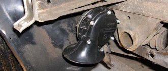
Where is the VAZ 2106 cooling fan relay located?
Dear visitors of the site “Everything about cars”! We will be very grateful for your comments on the video clip “Where is the VAZ 2106 cooling fan relay located?” registration is not required for this. We also ask you to let us know if you have any problems playing the video.
audi a3 2001 1. 6 rodator is cold and the temperature is 95 and one pipe is cold, what is it, help
Hello, I have a Mazda kapel 99g, I recently changed the coolant in the engine, after which the fan began to work very often, while the temperature needle does not rise above the middle at all, what could it be, any thoughts??
I took everything apart and bought a new one, but it turned out to be a relyushka.
very little, for example, my fan did not turn on due to the fact that antifreeze did not flow through the lower expansion tube, the thermostat stuck. At first the fault was with the sensor itself, but then when I crushed the pipe with my hands, antifreeze flowed into it and the sensor started working and started spinning. By the way, even the gasket on the lid was broken
Novel . I watch your videos often. Thank you very much . Everything is intelligible and understandable, and most importantly relevant.
Where have you been before with this video? I drove 340 km on Dolinsk non-carbonated water. The fan did not turn on.
Which fan is better, forced or electric? My fan turns the ramen, that is, it’s forced
I have an injection 2105, tell me where the sensor is located at the bottom of the radiator, it’s not like in the video
The sensors also seem to be sold differently, for example, at 92g. on And one more thing, I’m certainly not a mechanic, but if your thermostat is faulty, the system moves in a small circle: does that mean the sensor won’t work, or am I wrong?
thanks for the info
Hello, if you don't mind, please tell me. When I remove the contacts from the sensor and connect them to each other, the fan does not work. It only works directly from the battery. What could be the reason? the rest of the contacts are new
leave the car and drink beer, respect to the author
Well, I don’t know why the author works at 90. For me it turns on at about 100. Strange, of course. Maybe it's the sensor. I installed a new one.
No one says anywhere why, even though everything is working properly, the fan still doesn’t work
is there a relay here? I had it, but I replaced the relay and it was zero, so tomorrow I’ll try to test the sensor, and what should the relay number be? I had 527. and you?
Paasibo Bro
electronic is better in winter
beautiful about beer respect
well done guy explained everything clearly
Turn signal relay pinout
During operation, the standard turn relay may fail and in this case it needs to be replaced. Incorrect operation of the device becomes noticeable, especially when the control light stops lighting up. The main cause of the malfunction is incomplete closure of the device.
In other cases, the relay begins to function unstably, and the relay contacts close at different time intervals. In some cases, the volume level of the sound accompanying the operation of the device is significantly reduced. This can create a serious problem on the road when the device is activated without the driver noticing due to accidental contact while driving the vehicle.
These shortcomings are eliminated by replacing the standard device with an electronic design. In this case, the turn signal relay is connected according to the standard diagram shown in the figure. Pin No. 1 is positive, the second pin connects to the turn switch, the third connects to the warning light, and the fourth connects to ground.
All connections and contacts must be reliably insulated using electrical tape and cambric, which is a hollow plastic braid. This eliminates possible short circuits with other conductors. Certain inconveniences are created by the plastic housing of the electronic relay, which does not always fit in its standard location. However, home craftsmen quite easily overcome this difficulty and find the most optimal technical solution.
Installation and configuration instructions
Installing emergency lights on a VAZ 2101 is not a particularly difficult task; almost anyone can cope with it. To properly connect the emergency lights to a VAZ 2101 with your own hands, you need to prepare everything you may need to complete the task.
Set of tools and materials
So, what you need to prepare before starting the process:
- Locksmith tools, including wrenches, screwdrivers, pliers, etc.
- Insulating tape.
- Four-contact light signal relay from the “Six”.
- Six-pin button for activation.
- Five meters of installation wire (video by Alex Gordon).
Work execution algorithm
So, let's start the process:
- First you need to remove the center console. To do this, you need to unscrew the bolts that secure the trim to the steering column. You will also need to remove the side trims of the windshield pillars.
- Having done this, you can remove the instrument cluster. Be careful not to damage the device.
- Next, disconnect the wires from the light bulb that illuminates the glove compartment. Then unscrew the bolts that secure the sides of the glove compartment to the control panel, as well as the bolts that secure its lower part. After unscrewing all the screws, the glove compartment itself can be removed.
- Now you need to remove the screws that secure the bottom of the dash to the front cross member. Then the nuts of the upper fastening are unscrewed; it is best to reach them through the technological opening of the glove compartment.
- After completing these steps, you can remove the handles from the stove control panel. To do this, at the junction of the lever with the handle, use a screwdriver to bend the lower part of the upper handle, and at the lower handle, you need to bend the upper part.
- Next, you need to disconnect the connectors with wires from the control panel backlight switches, side lights, and also the stove. Then, using a wrench, you need to unscrew two more bolts that secure the fastenings of the stove control levers. After completing these steps, you will be able to dismantle the control panel.
- Now let's move on to installing and connecting the main elements. First, decide on the location of installation of the system power button. It should be installed on the center console so that the driver can reach it as quickly as possible if necessary. It’s still too early to install the button, but you need to decide on the installation location now, since this will determine how much wire you need. Now remove the old turn signal relay from the car and disconnect the three cables from it - usually they are colored black, gray-white and orange.
- Next, take a new six-wheel relay. The second contact of the relay must be connected to the wire that was removed from contact L on the turn signal relay, as well as to output 7 of the button.
- The first contact of the relay must be connected to the fourth contact on the button itself. The third contact is connected to the cable disconnected from contact P on the turn signal relay. Then you need to connect the cable from the fourth contact to ground, that is, the body of the vehicle - it is best to connect it to the relay fixing nut.
- The next step is to connect the button itself. The fourth contact of the button should be connected to the first contact of the relay used. Its second contact must be connected to the cable that was disconnected from the positive contact of the rotary relay. The seventh contact is connected to the second contact of the relay, and the first and third contacts are connected to the steering column turn signal switch; in this case, the order of connection does not matter.
- Now all you have to do is connect the eighth pin to any positive cable; alternatively, you can wedge it into the electrical circuit from the cigarette lighter. If you decide to connect the plus directly to the battery or generator unit, the circuit will need to be protected with a fuse.
- At this point, the installation procedure can be considered complete. All you have to do is securely fix the wiring to prevent chafing of the cables. Reinstall all previously removed interior trim elements, center console, glove compartment, etc.
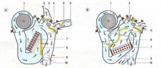
1. Relay connection diagram
2. Diagram of a penny turn switch
DIY turn relay
Sometimes situations arise when the standard turn signal relay fails and it is not possible to purchase a new device. In such a situation, you can try to make a turn signal relay with your own hands to provide the car with the necessary signals. The simplest electronic devices that you can create yourself are simple and easy to use, operate smoothly and reliably. High accuracy is achieved through the use of PWM controllers used in all circuits.
The simplest replacement for an electromagnetic relay is designed for a maximum load power of 150 W. It is connected to the positive terminal. If the IRFZ44 field switch is replaced with the IRF3205 model, then 200 W can be connected. This simple circuit ensures high accuracy of operation. The blinking frequency does not depend on the power of the light bulbs, so LED, halogen and other lamps can be included in the circuit.
The frequency of flashing is directly related to the capacitance of the capacitor. As the capacity increases, the light bulb will blink more rarely, and, conversely, decreasing the capacity will lead to faster blinking. The low-power 1n4148 diode can be replaced by any similar element. When the circuit reaches a power of 80 W, a slight generation of heat is observed in the field-effect transistor area. This means it is ready to use.
There is another simple circuit of a turn relay with a coil - simple, reliable and inexpensive. It is capable of lighting both regular light bulbs and LED ones and is designed for 12 V. The contacts are connected according to the principle of a regular switch, that is, in series with the light bulb. The LED is installed in the circuit as an indicator during commissioning work. The device parameters are adjusted by changing the resistance of the resistor.
Turn signals play an important role in road safety, and their failure can lead to a lot of trouble. A small device - a turn relay - is responsible for the operation of the turn signals. Read about what types of turn relays are used in VAZ cars, how they are designed and work, as well as about their malfunctions and repairs in this article.
Fan relay VAZ 2106 where is the photo Telegraph
Download file - VAZ 2106 fan relay where the photo is located
Ru Mail My World Odnoklassniki Games Dating News Search All projects All projects. Categories All project issues Computers, Internet Topics for adults Auto, Motorcycle Beauty and Health Products and Services Business, Finance Science, Technology, Languages Philosophy, Unknown Cities and Countries Education Photography, Videography Horoscopes, Magic, Fortune telling Society, Politics, Media Legal advice Leisure , Entertainment Travel, Tourism Humor Food, Cooking Work, Career About projects Mail. Ru Auto, Moto Motorsport Auto insurance Choosing a car, motorcycle Traffic police, Training, Traffic licenses, Driving Registration of auto-moto transactions Service, Maintenance, Tuning Other Auto topics. Questions - leaders Mercedes steering rack repair w 1 rate. Tomahawk and Starline car alarms Which alarm system will be better, Tomahawk TW or Starline A91? Category leaders Julia Sh. Anton Vladimirovich Artificial Intelligence. Where is the fan relay located on a VAZ? Premier Master, closed 6 years ago. Ivanych Prosvetleniy 6 years ago Under the hood If you stand at the right front wheel, 15 cm to the right of the washer reservoir Comment deleted Ivanich Prosvetleniy The charging light relay is right at the right wheel to the left of the battery 15 cm And the radiator fan relay, as I wrote, is only at the left front wheel It’s not far from there to the switch on sensor and to the vent Only I take it off for the summer On the pump with a six-blade and that's it Kuzbass Pro 6 years ago I had an A in the mounting block, and put it under the hood for a penny, you'd better buy a book or download it poorly without it, literature is a thing good. Yurich Pro 6 years ago It was a long time ago. In my opinion, there is a body part on the left mudguard, and not the rubber one near the wheel under the hood. There seems to be an expansion tank nearby. In general, remove the wires from the temperature sensor on the radiator, close it so that the relay works and you will hear which switch clicks. It’s a bit collective farm, really, but what did Denis Druzhin remember? Student 6 years ago Catch it, you’ll find everything.. Ru About the company Advertising Vacancies. We are constantly adding new functionality to the main interface of the project. Unfortunately, older browsers are not able to work well with modern software products. For correct operation, use the latest versions of Chrome, Mozilla Firefox, Opera, Internet Explorer 9 browsers or install the Amigo browser.
DIY burning heart for a wedding
procedural map
Samples of comic certificates
Problems in the field of financing in the Russian Federation
Purpose of the turn relay
The Traffic Rules in force in Russia clearly state that when making maneuvers, it is necessary to turn on the direction indicators, and in their absence, indicate the direction of movement with your hand. However, now most cars and motorcycles are equipped with turn signals, so you rarely need to use your hands to indicate the direction of travel.
When turned on, the direction indicators flash, that is, they light up and go out at certain intervals, so they attract the attention of other road users, and it is quite difficult not to notice the turn signal being turned on. The blinking of direction indicators also serves another role - it does not allow drivers to confuse their activation with the activation of brake lights or the activation of side lights.
Periodic turning on and off (that is, the same blinking) of the direction indicator lamps is realized using a simple device that is part of the vehicle's electrical system - a turn relay, which is often simply called a breaker or breaker relay.
The breaker relay included in the turn signal circuit performs three functions at once:
- Supplying electric current to the direction indicator lamps (that is, turning on the “turn signals”);
- Ensuring intermittent operation of the direction indicator lamps (their blinking);
- Creation of characteristic clicks, signaling to the driver of the car that the direction indicators are working.
In cars of the Volzhsky Automobile Plant of various generations and models, several types of turn relays are used, which have different operating principles and characteristics.
Types and location of installation of turn relays in various VAZ models
There are two main types of turn relays used in VAZ cars:
- Classic electromagnetic-thermal relays;
- Modern electronic relays.
The operation of these relays is based on various physical principles, which will be discussed in more detail below. Here we will talk about the applicability and installation features of different types of relays.
Electromagnetic-thermal turn relays were installed on early VAZ “Classic” models: 2101, 2102 and 2103. Several models of this type of relay were produced and are still being produced; today the RS series relays are most used: RS491M, RS491B, RS57, RS950 and others. These relays are often called “barrel” due to their external design.
Electronic relays began to be installed on VAZ cars, starting with model 2104, and today all current Lada models are equipped with this type of relay. Quite a few models of electronic relays are produced, the most widely used are turn relays 23.3747, 231.3747, 494.3747, 6422.3747 (all installed on models 2104 - 2107), 26.3747, 49.3777, 491.3747, 495.3747 and 712.3777 (all installed on models 2108 – 2110), 07.4747 ( installed on models 2108 – 2115), 14.3747 (installed on the entire line of VAZ “Classic”, VAZ-1111 “Oka”, VAZ-2121 “Niva” and other cars), etc.
Also today, electronic turn relays are produced for VAZ-2101 - 2103 cars, which can be installed without modifications instead of the standard electromagnetic-thermal ones. The most widely used relay is type 71.3777, however, Kopeyki can also use some of the relay models described above.
The installation location of the turn signal relay depends on the car model. So, on Zhiguli 2101 - 2106 the relay is mounted directly under the front instrument panel (the ignition relay is also installed there in some models), so it is well protected, and its clicks are clearly audible in any conditions. In later models, the turn relay “migrated” to the relay and fuse mounting block. You need to know the location of the relay, as this can greatly facilitate its replacement in the event of a breakdown.
Lighting repair
Possible causes of malfunction
How and where to connect the DVR in a car correctly How to conduct, lay the wire from the DVR diagram
So, if the low beam on a VAZ 2106 in one of the headlights has disappeared, then, as mentioned above, most likely the light bulb has burned out.
If replacing the lamp does not produce results, then the following malfunctions may occur:
- The contacts in the block are oxidized or burnt;
- The fuse has blown;
- The relay has failed;
- The switch is faulty;
- There is a break in the circuit.
Below we will take a closer look at how to diagnose and fix the problem.
H4 standard double filament bulb
Replacing a light bulb
First of all, it should be said that the low beam lamp on the VAZ 2106 complies with the H4 standard, i.e. it has two threads, which allows the headlight to operate in two modes. Currently, such light bulbs are produced by different companies, both well-known brands and little-known companies.
It should be noted that domestic light bulbs are very popular among car owners. Their price is significantly lower than their imported counterparts, but at the same time they are not inferior in quality.
Instructions for doing this work look like this:
First of all, you need to use a flat-head screwdriver to dismantle the plastic panel that frames the headlights.
The photo shows the dismantling of the plastic panel
- Then use a Phillips screwdriver to loosen the clamps that hold the headlight.
- Next, you need to slightly turn the metal hoop and dismantle it.
Headlight fixing screws
Now you can pull out the headlight with your own hands and disconnect it from the block
At this stage, you need to pay attention to the connector contacts. If necessary, they need to be cleaned. Then you need to unfasten the lock and remove the light bulb. Next, the work is performed in the reverse order - a new lamp is installed, which is pressed with a clamp, and the block is connected to the contacts
The headlight assembly must be installed in place and secured with a hoop. To complete the work, a plastic panel is inserted, on which you need to press lightly until you hear a characteristic click.
This completes the process of replacing the light bulb.
Replacing fuses
If after replacing the light bulb the low beam headlight on 2106 still does not light, you should check the fuses. They are located under the instrument panel.
Fuse box location
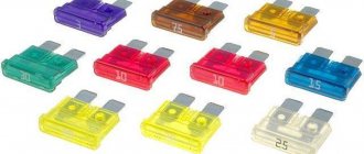
In this case, you need to pay attention to two fuses:
- No. 5 – protects the left headlight from short circuit;
- No. 6 – protects the right headlight.
It must be said that the low beam on the VAZ 2106 often does not work due to the fuse contacts being bent or oxidized. In this case, they need to be bent and cleaned. If the protective element has melted, it must be replaced.
Fuse diagram
Troubleshooting other problems
If the low beam on a VAZ 2106 does not light up, then to detect a malfunction you will need a multimeter to test the wiring, or at least a test light. The circuit and equipment should be checked according to the diagram below.
Headlight switching diagram
It must be said that the high and low beam relays on the VAZ 2106, which are indicated in the diagram as numbers 6 and 4, often fail.
Therefore, you can start checking with them.
Low beam relay for VAZ 2106 (no. 3)
- If there is no voltage supplied to the relays and fuses, you should check the wiring section from switch No. 5 to terminal No. 86 on the relay, as well as the section from the switch to the external lighting switch No. 8. If the machine's wiring is normal, then the switch has failed.
- If voltage is supplied to the fuses, then an open circuit must be looked for in the area from the block to the headlights. Often the breakdown is due to poor ground contact. In this case, you just need to clean the contact.
These, in fact, are all the reasons why external lighting may not work on the “six”.
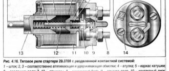
Design and principle of operation of an electromagnetic-thermal turn relay
Relays of this type do not have a very complicated design. It is based on an electromagnetic relay of a traditional design - a cylindrical core with a winding of thin copper wire. At the top of the core there are two contact groups, and on the sides there are flexible metal anchors (or, as they are called, anchors). One contact group is designed to close the circuit of the turn signal indicator lamp located on the dashboard. And the second contact group directly closes the circuits of the direction indicator lamps, and it is its design features that ensure the blinking of the turn signals.
The armature of the contact group of the turn signal lamps is pulled away from the contact located on the core using a thin nichrome string, so in the normal position the turn signal circuit is open. The opposite end of the string is fixed on a platform made of insulating material, which serves as the basis for installing the core. The nichrome string is connected through a resistor to the turn signal switch circuit, so current flows through it during operation of the relay.
This entire structure is placed in a cylindrical metal case; the bottom of the case is a platform made of insulating material with a relay. At the bottom of the platform there are contacts with the help of which the breaker relay is connected to the turn signal circuit.
The operation of an electromagnetic-thermal relay is quite simple and boils down to the following. When the turn signal is turned on, a circuit is closed that includes the turn signal lamps, a resistor, a relay winding and a nichrome string. Due to the resistance of the resistor, the voltage supplied to the lamps is low, so their filaments burn at full heat. Nichrome, as is known, has a high resistivity and heats up greatly when current flows - thanks to this heating, the nichrome string increases its length, and the armature pulled by it, under the influence of the attraction of the core, straightens and at some point closes the contact group. As a result, current begins to flow bypassing the resistor and the nichrome string, and the turn signal lamps light up in full force.
However, stopping the heating of the string leads to its cooling and shortening, and the armature is again pulled away from the core, opening the contacts - the turn signal lamps go out, and the cycle repeats again. The heating and cooling of the nichrome string occurs quickly, so the lamps blink at a frequency ranging from 60 to 120 times per minute.
The current position of the contact group of the direction indicator lamps (let's call it the first) is associated with the work of the contact group of the signal lamp (let's call it the second). When the contacts of the first group are open, current flows through the winding, but it is not enough to attract the armature of the second group, so the signal lamp does not light up. When the string is pulled and the first contact group is closed, the current flowing through the winding increases sharply, and it is already sufficient to attract the armature of the second contact group. As a result, simultaneously with the blinking of the direction indicators, the warning light on the dashboard also blinks.
Characteristic clicks during operation of the direction indicators occur due to the impact of the anchors on the contacts when they are closed and opened. Clicking is a characteristic feature of electromagnetic relays, and it comes in very handy in breakers.
The electromagnetic-thermal relay has a simple design, and this is its main advantage. But this type of relay has many more disadvantages: over time, the string is stretched, as a result of which the relay stops functioning normally, during operation the relay heats up, which changes its characteristics, and if one of the turn signal lamps burns out, the blinking frequency of the second lamp decreases significantly, and In some cases, the lamp stops lighting up altogether.
Today, electromagnetic-thermal relay-interrupters have been replaced by more modern and advanced electronic relays.
Malfunctions of turn signals VAZ 2107
The main symptom of a malfunction is non-functioning direction indicators. However, the reason may not be only the relay. There are several possible breakdowns:
- The turn signal lamps are constantly on and do not blink. This indicates a malfunction of the electromagnetic part of the VAZ 2107 turn signal relay - the contacts are stuck in the closed position and do not open. This could be either a burnt-out contact of the electromagnetic relay or a failure of the electronic circuit of the turn relay. Regardless of the specific reason, there is only one way out - replacing the VAZ 2107 turn signal relay.
- Lights flash too slowly or quickly. The reason may be either in the electronic part of the turn relay or in the discrepancy between the current consumption of the lamps and the nominal one. If one of the lamps has burned out or lamps that consume less current are installed, the turns will flash more often than necessary. The same phenomenon occurs if the wire going to one of the lamps is broken, or the lamp socket or base is oxidized. A similar phenomenon occurs when installing LED lamps instead of incandescent lamps. When installing more powerful lamps, the blinking frequency decreases. If all the lamps are in working order and the malfunction did not appear after replacing the lamps, the reason lies precisely in the turn relay or poor contacts in the lamp power circuit.
- The direction indicator lamps do not light up. The cause of the malfunction may be the polo