Pass-through and crossover switches
I have an article on this issue. It says that if you need to control the light from 2 places, pass-through switches (or switches, as people say) are used. To each of them you need to lay three wires.
The scheme will be like this:
Classic lighting switching scheme from two points with pass-through switches
If there are 3 or more light control points, you need to install cross switches (except for the two pass-throughs at the edges of the circuit), with 4 wires laid to each of them:
Circuit with a cross switch for turning on lighting from three places
If you need control from 4 places, but you need 2 pass-through and 2 cross switches, respectively:
Scheme of two pass-through and two cross switches for turning on the light from four places
And so on, the number of cross switches increases.
Disadvantages of circuits with pass-through and crossover switches
Some disadvantages of classic circuits with switches may seem unobvious or insignificant, but I will still list them.
- Pass-through and cross-over switches have a higher price tag than regular switches.
- They are often out of stock in stores.
- More wiring required.
Light control using pulse relays
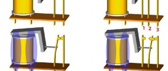
Let me remind you that a pulse (bistable) relay is a relay that changes its state every time it receives an action from the switch.
We can say that a pulse relay divides the frequency of incoming pulses by two.
Read my old article on the design and connection of a pulse relay (bistable switch) from the Belarusian company Euroavtomatika FiF.
By the way, I also have an article on F&F - Voltage control relay EuroAutomatika F&F CP-721.
A big plus of a pulse relay is that you can connect as many switches (more precisely, non-latching buttons) to its input as you like, within reasonable limits.
Minuses -
- We depend on the controller and its software, which can fail due to interference and other influences, including service life.
- Not everyone likes the fact that some kind of automation decides when the lights should be turned off. Some people want to be in complete control of the situation, rather than waiting for the lights to go off on a timer. Or won't it turn off? Is the counter ticking?
- Not everyone likes it when non-latching buttons are used instead of the usual switches, in which everything is clear/understandable.
To be fair, I will say that such relays are now quite often installed in houses where there are rooms with several inputs/outputs.
However, what should you do if for some reason you cannot install a pulse relay? For example, the owner does not want to install buttons because he has already bought switches? But you can’t install crossover and pass-through switches, because... Are there 2 wires per switch in the wall? Or are there no crossover switches on sale (by the way, there are problems with this in Taganrog)?
I suggest a way out:
Connecting the water pressure switch
The water pressure switch for the pump is connected to two systems at once: electricity and water supply. It is installed permanently, since there is no need to move the device.
Electrical part
To connect a pressure switch, a dedicated line is not required, but is desirable - there is a greater chance that the device will work longer. A cable with a solid copper core with a cross-section of at least 2.5 square meters must run from the shield. mm. It is advisable to install a combination of automatic + RCD or difavtomat. The parameters are selected based on current and depend more on the characteristics of the pump, since the water pressure switch consumes very little current. The circuit must have grounding - the combination of water and electricity creates a zone of increased danger.
Connection diagram of the water pressure switch to the electrical panel
The cables are inserted into special inputs on the back of the case. Under the cover there is a terminal block. It has three pairs of contacts:
- grounding - the corresponding conductors coming from the panel and from the pump are connected;
- line or “line” terminals - for connecting the phase and neutral wires from the panel;
- terminals for similar wires from the pump (usually on the block located above).
Location of terminals on the water pressure switch housing
The connection is standard - the conductors are stripped of insulation, inserted into the connector, and tightened with a clamping bolt. By pulling the conductor, check whether it is securely clamped. After 30-60 minutes, the bolts can be tightened, since copper is a soft material and the contact may weaken.
Pipeline connection
There are different ways to connect a water pressure switch to the plumbing system. The most convenient option is to install a special adapter with all the required outputs - a five-pin fitting. The same system can be assembled from other fittings, it’s just that it’s always easier to use a ready-made version.
It is screwed onto the pipe on the back of the housing; a hydraulic accumulator, a supply hose from the pump and a line that goes into the house are connected to the other outputs. You can also install a mud pan and a pressure gauge.
An example of tying a pressure switch for a pump
A pressure gauge is a necessary thing - to monitor the pressure in the system, monitor the relay settings. A mud trap is also a necessary device, but it can be installed separately on the pipeline from the pump. In general, a whole system of filters for water purification is desirable.
With this scheme, at high flow rates, water is supplied directly to the system - bypassing the hydraulic accumulator. It begins to fill after all the taps in the house are closed.
Light control from several places using intermediate relays
An intermediate relay is, in principle, an ordinary relay that can perform the following functions (or one of them):
- Galvanic isolation,
- Transition from one voltage level to another (or from one type of current to another),
- Current amplification when the control current is much less than the contact current,
- Execution of logical functions,
- Reproduction of contacts (from one switching you can make 4, for example).
It is precisely the last function that will help us make pass-through and crossover switches on the relays, while using ordinary switches to control these relays.
The diagram will help you understand what is written:
Scheme with 2 pass-through switches and 2 relays. Switching on lamps from four places
That is, relays with their contacts imitate cross switches.
We can go further - we use 4 relays and 4 regular switches!
Circuit with 4 relays to simulate a circuit with 2 pass-through and 2 crossover switches
In the diagram, S1, S2, S3, S4 are ordinary familiar switches. People who are far from electrical and automation will find it easy and simple to understand this system.
Connection methods
Installation of the PTF switch off button
So, if the installation of fog lights is carried out at home, then in order to do everything correctly, put the kit in the bumper instead of plugs and connect it to the wiring, you can use one of two connection options. As we remember, PTFs are not turned on by side lights in any case; this must be remembered before installing the kit in the bumper and connecting all connectors. There may be several options for installing devices. One of the easiest in terms of installation and reliability is to connect to vehicle wires that are already wired and designed for fog lights.
In this case, everything can be made simpler. The factory wiring is already equipped with all the necessary components, in particular, the wires and connectors that are needed for connection. The wiring contains all the relays and fuses, as well as a switch that can be used to control the devices. In fact, all you have to do is remove the plugs from the bumper and install the PTF kit, connecting it to all connectors. This option is not relevant for all vehicles, but only for cars equipped with plugs or cars where it is necessary to change faulty fog lights (the author of the video is Andrey Kuvshinov).
When purchasing a PTF kit, you need to make sure that this model can be installed on your car. Not only the connectors must match, but also the installation parameters. If the vehicle is not equipped with wiring for installing fog lights, you will need to do it yourself. In order for the fog lamp connection diagram to be correct, additional wires should be purchased along with the kit; they must be copper and insulated. In addition, you also need to purchase a fog light switch, a fuse and a relay; sometimes these components are included with the PTF.
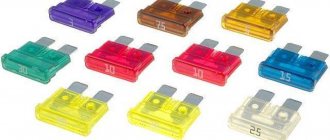
Remember that under no circumstances should fog lights be turned on along with the dimensions. Standard wiring, as well as the switch, are not designed for the level of current that these optics draw. It should be noted that the electrical circuit must in any case be equipped with a fuse, this is very important. Only a fuse will save your vehicle from fire if a short circuit accidentally occurs in the circuit. The fuse itself must be powerful enough - the power level is calculated in accordance with the power of the optics itself.
We recommend: Signs of a bad car battery. When the time has come
For example, if the optics are designed for 60 watts, then when purchasing a fuse, you must calculate its power in advance in accordance with the formula:
60 W * 2 / 12 V = 10 A
That is, the device itself must be selected taking into account a small margin. The best option would be to purchase a 15 amp fuse.
Implementation of a lighting control circuit using intermediate relays
My regular reader Nikolai put together the proposed scheme. The task was to turn on the lights from four places in a large public room, and use switches rather than buttons. There were 3 wires connected to each switch, and touching the tiles was not an option at all.
Build process:
Assembling a circuit using switches and relays
Please note that Wago 221 5-pin terminals are used, mounted on a DIN rail through a special holder.
I have a lot of articles on Wago, here is the main one.
Assembling and debugging a lighting control circuit using a relay
Finder relays with a 230V coil are used as intermediate relays.
Lighting control circuit using a relay and modular contactor
Since powerful spotlights are used, the power of which is more than 2 kW, a modular contactor with a contact current of 25A is used. The contactor separates the “logical” and power parts.
Please note that this contactor has 3 positions – On, Automatic (coil controlled), and Off.
The scheme turned out to be as follows:
Scheme with 2 pass-through switches, 2 relays and a modular contactor
For those interested, read how a contactor is fundamentally different from a starter.
By the way, I used a similar modular contactor in a homemade ATS to connect a generator to the house. There I recommended connecting the coil in series with a resistor to reduce its heating when turned on for a long time.
And the installation process in the utility room (electrical room) looked like this:
Installation of a lighting control system from 4 places
The cable used is NYM, copper monocore round.
Thank you for your attention, please share your opinions and ask questions in the comments!
Electrical connection diagram
Depending on the needs of the user and his financial capabilities, you can choose one of the methods of connecting the deep pump to the electrical network.
Without automation
Without auxiliary control devices, the pump is connected using a pre-installed electrical outlet with a grounding contact. The pump is also grounded. For this purpose, the main bus of the house is used, connecting to the existing ground loop of the building.
A three-core cable is used to supply electricity to the outlet. The power supply voltage of the submersible pump is 220V. 380-volt or 150-volt outlets cannot be used.
Via pressure switch
To reduce the cost of a set of pressure equipment, you can use a connection diagram for a well pump only with a pressure switch without a control unit. The device turns off the pump when the pressure reaches a maximum, and starts it when the pressure drops to a minimum.
Using control unit
When selecting an automation model, you first need to find out what protective system is already installed in the pump by the manufacturer. Modern devices are already protected from overheating and idle operation. Sometimes the equipment is equipped with a float mechanism. Taking this data into account, you can choose one of three automation options - simple, with a second or third generation electric control unit.
The simplest protection is most often used for automatic water supply. The control unit here is assembled from three devices:
- Dry running blocker. It will turn off the device, which operates without water, preventing overheating. Sometimes the additional installation of a float switch is allowed. It performs the same functions, turning off the pumping equipment when the water level drops, preventing it from overheating. The devices may seem primitive, but they provide effective protection for the electric motor.
- Hydraulic accumulator. Without it, it will not be possible to provide automatic water supply. The hydraulic tank works as a water storage tank. Inside there is a working mechanism - a diaphragm.
- Pressure switch equipped with a pressure gauge. This device allows you to configure the operation of relay contacts.
It is not difficult to equip pressure equipment with simple automation with your own hands. The principle of operation of the system is simple: as water flows, the pressure in the hydraulic tank decreases. When the minimum value is reached, the relay starts the pressure equipment, which pumps water into the storage tank. When the pressure in the hydraulic accumulator reaches its maximum, the relay device turns off the installation. As water is consumed, the cycle repeats.
The pressure limits in the storage tank are adjusted using a relay. In the device, using a pressure gauge, the minimum and maximum response parameters are set.
In second-generation automation, the connection is made through an electrical unit with a set of sensors. They are mounted directly on pressure equipment, as well as inside the water supply network, and allow the system to function without a hydraulic tank. The impulse from the sensors goes to the electronic unit, which controls the system.
Operation of pressure equipment with this scheme for connecting a submersible well pump to automation:
- Liquid accumulates only in the water supply where one of the sensors is installed.
- When the pressure drops, the sensor sends a pulse to the control unit, which starts the pump.
- After reaching the required pressure of the water flow in the water supply, the pump is turned off according to a similar scheme.
To install such automation, you will need basic knowledge of electrical engineering. This and the previous protection work almost identically - based on water pressure. However, the electric unit with sensors is more expensive, which is why it is not so popular among consumers. Even when using automation, you don’t have to use a hydraulic tank, although if there is a power outage, you won’t be left without water. There is always a reserve left in the drive.
Third generation automation is reliable, high quality and expensive. Its installation allows you to significantly save on electricity due to ultra-precise tuning of the electric motor. The connection diagram for advanced automation to a deep well pump is very complex, so you should contact a professional to connect it. But it provides complete protection of the motor from various breakdowns, for example, overheating during dry running or burning of the windings during power surges.
The unit operates from sensors without a hydraulic tank. Efficiency is achieved through fine adjustments.
Switching on from different places using relays and limit switches
At the request of reader Zoltan, I quickly sketched out a circuit that turns on and off two groups of lighting on the street and in the garage. In this case, pushbuttons, limit buttons and relays are used.
Scheme for turning on the light through the end buttons, Start, Stop buttons and relays
I took inspiration from here:
Algorithm and discussion of the scheme in the comments, starting January 16.
By January 26, after several intermediate options, the following scheme was born:
Lighting circuit on a relay with a motion sensor, limit switch and time relay
And then the author of the video sent Zoltan his diagram, here it is!
Automation circuit for turning on lights from different places
Connecting PTF via relay and button
There are several options for pairing the PTF with the vehicle’s on-board network. Connecting fog lights via a relay using a separate button is the most convenient, safe and correct solution. To complete the job you will need:
- fog lights;
- connection terminals;
- 15 amp fuse;
- four-pin relay;
- connection block;
- wires;
- insulation or heat shrink tubing.
The materials are included in the installation kit and are sold in one set with PTF.
The tools you need are screwdrivers, pliers and a knife for stripping wire insulation.
The wiring must be carried out according to the plan for parallel or series connection of lamps.
The connection diagram for fog lights is shown in the figure.
Operations for connecting PTF are performed in the following sequence:
- Disconnect the negative terminal from the battery;
- Securely fix the relay in the car interior. The space under the instrument panel is suitable for this.
- Secure the button for turning on the fog lights on the “dashboard” (usually there is a separate place for it, covered with a plug).
- Lay the wire from the battery to the relay, secure the terminal on it and connect it to contact “30”.
Important: a fuse must be inserted into the electrical circuit between the battery and the relay, which is best located in the engine compartment close to the battery. This will prevent the wiring from catching fire if there is a short circuit to the housing.
- Connect the button and the 85th relay pin.
- Connect the positive cable to the button input, extending it from the contact lock on the ignition switch. The power supply should be connected to a place where voltage is supplied only after turning the key. This will prevent you from leaving the PTF lights on when parking the car.
- Connect contact “86” to ground using the nearest bolt or self-tapping screw.
- Attach the PTF to the front bumper by removing the plastic plugs. Sometimes there are no special places for attaching PTFs. Then you will have to cut them with a jigsaw or fix the headlights on steel brackets above the bumper.
- Lay the cables from the 87th contact of the relay to the fog lights, connecting them to the sockets.
- Connect the mass output of the PTF to the body.
- Place and secure the negative terminal on the battery.
- Turn the ignition key and make sure the fog lights are working.
During installation, you should insulate the wire connections and terminals using heat-shrinkable tubing or electrical tape.

