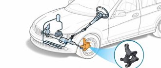
Sound signal VAZ 2107
The manufacturer of the VAZ 2107 equipped the car with two versions of the sound signal (S). In the first case, two sound elements (SE) of low and high tonality were installed (signal types S-304 and S-305), which made it possible to obtain a loud and surround sound. These elements were mounted on a metal bracket in the engine compartment near the radiator of the cooling system.
The sound signal of the VAZ 2107 consists of two elements of different tones - S-304 and S-305
The second option involved installing one ZE type 20.3721–01, also located on a bracket in front of the cooling radiator. All sound elements are non-separable and cannot be repaired.
The sound signal of the VAZ 2107 consists of one element 20.3721–01
Purpose of the sound signal
The sound signal is designed to warn road users of danger and prevent accidents. The signal is given by pressing the ZS button, which is located on the steering wheel.
Traffic rules limit the use of ES to two situations.
Traffic rules Chapter 19.10. Sound signals can only be used:
– to warn other drivers about the intention to overtake outside populated areas;
– in cases where it is necessary to prevent a traffic accident.
Traffic rules of the Russian Federation
https://www.pdd24.com/
In the first case, the vehicle informs the driver of the car being led before the start of the maneuver. The situations that fall under the second paragraph of the traffic rules are more varied. The following options are possible.
- During icy conditions, a person is walking along a pedestrian crossing, and the slippery road does not allow you to brake sharply. Having heard the signal, the pedestrian will react.
- The driver moving in the next lane did not see you in the side mirror and began to change lanes. By giving a signal, you will draw his attention to you.
- An animal came out onto the roadway. You can use a sound signal to drive him off the road.
- When leaving a secondary road, the driver did not see your car moving along the main road. ZS will force him to stop his car.
- The cyclist moves not along the edge, but in the middle of the roadway. The sound of the signal will make him let the car pass.
There are many such cases. Timely and reasonable use of traffic signals will allow road users to avoid big troubles.
Sound signal device VAZ 2107
The housing of the electronic device contains a metal membrane, which oscillates due to the movements of the metal armature. These vibrations are the source of sound. The armature itself is driven by a magnetic field created by a coil and winding.
The VAZ 2107 sound signal is designed quite simply: 1 - yoke; 2—ZE building; 3 - winding; 4 - core; 5 - anchor; 6 — adjusting screw; 7 - bridge; 8 — textolite plate; 9 — fixed contact holder; 10 — movable contact plate; 11 - membrane; 12 — diffuser; 13 - ring
The principle of operation of the ZS VAZ 2107 is as follows. The electromagnetic field that occurs when voltage is applied to the coil pushes out the membrane armature, which, in turn, opens the breaker and turns off the coil. As a result, the membrane returns to its original position, and the armature again closes the breaker contacts. As a result of repetition of such cycles, the membrane vibrates, producing sound.
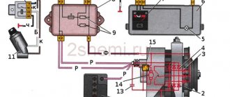
Electrical diagram for connecting the sound signal of VAZ 2107
The connection diagram for a VAZ 2107 sound signal with two elements of different tones is quite simple.
VAZ 2107 sound signal connection diagram: 1 - sound signals; 2 - relay and fuse block; 3 — signal activation button on the steering wheel; РЗ — sound signal relay; A - generator plus
The principle of operation of the VAZ 2107 sound signal
Voltage is supplied to the terminals of the sound elements through a relay designed to close and open an electrical circuit with a high load. This low current controlled relay avoids overloading some controls. Its malfunction can lead to overheating of control buttons and toggle switches and their failure.
When the contacts of the signal activation button are closed, terminal 85 of the relay is connected to ground (the negative terminal of the battery). In this case, positive is constantly supplied from the generator to terminals 86 and 30 of the ZS relay. Terminals 85 and 86 are the negative and positive of the relay coil. When voltage is applied to them, the contact between terminals 30 and 87 is closed. A plus is supplied to the last terminal, which is connected to the positive contact, through the normally open contact. As a result, when the negative contact of the protective element is constantly connected to ground, an audible signal is triggered.
How to connect a signal with two pins
Method of connecting the horn
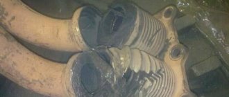
The standard signal of front-wheel drive vehicles is, to put it mildly, inexpressive. For a long time I wanted to change it to something more serious. I didn’t consider pneumatic “pipes” as a matter of principle, but ordinary two-tone “snails” seemed to me the best option.
Here they are, snails in a box. Upon closer examination, I discovered quite decent workmanship, there were even traces of tuning each signal to its own frequency!
Having carefully studied the instructions printed on the box, I was surprised to discover that the emitters should not be placed haphazardly, but in a strictly defined position.
Recommended installation diagram for emitters. It’s good that you wrote it, it would never have occurred to me!
Having removed the decorative radiator grille and the standard signal, I began to bend the plates included in the kit for attaching the signals.
The bells of the emitters had to be turned slightly in different directions, otherwise they would not fit under the decorative grille.
Then I screwed the finished brackets with self-tapping screws to the radiator frame, positioning them in such a way that the emitters did not come into contact with either the car body or each other when vibrating. Here you can connect the signals directly to the battery for testing; the signal sound should be clear, without extraneous sounds or rattling.
The terminals were made of thick brass, tinned. I also bought clear polyurethane caps to protect the connector. I also dressed all the wires in a thin “corrugation”..
Next I started connecting the horn. The standard signal has a switching circuit without a relay, with a 20 A fuse (together with the radiator cooling fan) and is triggered when there is a short circuit to ground. Its maximum current consumption is 5 A. New emitters consume current up to 4 A each, so it is quite possible not to use a relay. But I decided to do everything the right way and connected the emitters according to the attached diagram.
Standard connection diagram from the book. It is worth noting that the signal is turned on by switching the negative wire, so signals with one contact cannot be connected normally without using a relay.
Diagram for connecting horns with two contacts. I used a regular relay, took +12V from the battery.
The article was compiled based on publications by Dmitry Tsypchenko from Moscow.
I remind you! That the editors are not responsible for any unlawful and illegal use of materials published in the encyclopedia.
Compiled by Patlakh V.V. https://patlah.ru
© “Encyclopedia of Technologies and Methods” Patlakh V.V. 1993-2007
Source
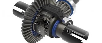
Installing an additional button on the VAZ 2107 sound signal
The moving contact between the steering wheel and the steering column of the VAZ 2107 fails over time. His foot loses elasticity and the contact parts no longer touch. To prevent such a situation, car owners often install an additional button to sound a sound signal, duplicating the functions of the button on the steering wheel, that is, connecting the relay to ground. It is installed in any convenient place, most often on the instrument panel near the steering wheel.
Often VAZ 2107 owners install an additional button to sound the sound signal.
An additional button is installed as follows.
- We make a hole of a suitable diameter on the instrument panel.
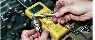
- We install the button in the hole made.
- If the button is three-contact, we determine which contacts close when it is pressed. This can be done using a multimeter.
- In the common wiring harness, we find the wire going to the ZS button on the steering wheel. This is usually a gray wire with a black stripe.
- We connect this or a wire parallel to it to one of the contacts of the button.
- We connect the second terminal of the button to ground.
A button connected in this way will repeat the functions of a button on the steering wheel.
Personal experience shows that using the signal button installed on the instrument panel is inconvenient. You won’t be able to get used to it enough to promptly sound a beep without looking at it. As a result, precious fractions of a second are lost when they could be vital. It's worth spending the money and taking a little time to fix your steering wheel signal.
What is a signal?
A signal is something that can be transmitted through space and time. So, what conditions must exist to call a signal a “signal”?
Firstly, the signal must be created (generated) by someone.
Secondly, the signal must be intended for whom.
Thirdly, someone must accept this signal and draw some conclusions for themselves, that is, interpret the signal correctly.
Let's plunge into the Wild West.
I think it's no secret that the Indians lit a fire, and the smoke from the fire was used to transmit a signal. This means that in our case the fire is a signal generator. So, the first point works). Who was the smoke from the fire intended for? For cowboys? Of course not! For our own Indians. So point two works. Okay, you saw two columns of smoke rising into the sky. Does this mean anything to you? Someone is probably grilling kebabs? May be. But if you approach these fires, then they will make a shashlik out of you). For the Indians, these two columns of smoke meant that their detachment had successfully hunted the cowboys ;-). Well, the third rule has been fulfilled ;-).
Installation of a pneumatic sound signal on a VAZ 2107
Some car owners install a powerful pneumatic sound signal on the VAZ 2107. Installation of such a device is quite simple. You will need a grinder, a drill and a standard set of plumbing tools.
Universal pneumatic horn model fits most cars
First you need to determine where the horn and compressor will be located, and then make brackets to mount them. Typically, the pneumatic signal is installed behind a decorative grille in front of the radiator.
The pneumatic signal is usually placed in front of the cooling radiator
Installation is carried out in the following order:
- We make brackets from a suitable material (metal corner or strip).
- We install the brackets on the top panel in front of the cooling radiator in accordance with the dimensions of the pneumatic claxon and the design of its fastenings.
The manufactured brackets are screwed into places suitable for attaching the pneumoklaxon - We install the pneumoklaxon on the brackets.
- We mount the compressor on the standard signal brackets or on the panel near the radiator.
The air compressor is installed next to the cooling radiator - We connect the horn and the compressor with a hose from the pneumatic signal kit.
- We connect power to the pneumoklaxon from the standard AP.
If the current consumed by the compressor is more than 5 A, according to the scheme described above, you will need to install an additional relay to be on the safe side.
A pneumatic horn is impractical because it is equipped with a compressor that has a delay in starting. The compressor is short-lived and may quickly require replacement; moreover, in severe frosts, the compressor may fail and the signal will not sound.
In practice, the installation algorithm for a pneumoklaxon is determined by its size, type, design of fastenings, etc.
The working principle of a car horn
Like the design diagram of horn and hornless sound signals, their operating principle is largely similar. The main actuator in both cases is an electromagnet. Power is supplied to the coil through the breaker contact group. The sound source is a membrane rigidly connected to the armature of the electromagnet. When you press the signal button, a current is supplied to the magnet, which sets the armature in motion - being attracted to the core, it affects the membrane, which begins to bend.
This is a cyclic process: as the armature moves, the contacts of the breaker begin to open, the membrane, trying to return to its previous position, puts pressure on the armature, which also returns to its normal place. It is the vibrations of the membrane that form the sound, the tonality of which depends on the frequency of the horn.
Cars usually use a parallel circuit for generating low/high pitch signals, which as a result overlap each other quite harmoniously, generating a multi-tone audio signal. As a rule, in absolute value the difference between high/low frequency signals does not exceed 70-100 Hz.
In addition to frequency and sound level, a car signal is characterized by such parameters as spectral composition and sound pressure level (a value measured in decibels). Transport noise is best covered by sound whose frequency spectrum is in the range of 1800-3500 Hz. All parts of a car horn are oriented towards these values, from the membrane to the resonator, as well as their shape, configuration and materials of manufacture.
Lada 2107 Lastochka NUMBER ONE › Logbook › Volgov signal instead of stock.
I haven’t written for many months, I’m slowly working on the car. Finally, I brought one more thing to an end, I can tick it off. I’ll say right away that there are a lot of articles about installing the Volgov signal on a VAZ, so I will describe the process briefly.
After reading articles a long time ago, it occurred to me that it is not at all necessary to install a relay to install signals from the Volga. Therefore, having bought two horns at a car store, I calmly went straight away to install them.
My surprise was huge when I realized that on a VAZ the horn is closed and opened, roughly speaking, by a minus button on your steering wheel. But Volgovsky Signal does not like such fraud. It is necessary to connect via a relay, otherwise the beeps will immediately start screaming - closing/opening on the positive side. Here's the diagram:
We will need a 4-pin relay, a positive wire (about a meter), heat shrink and female-male terminals.
There are no problems in choosing terminals, relays and heat shrink. How can we choose the wire of the cross section we need? Tables from the Internet helped me and here’s something else:
“In short, make it a rule: 1mm2 wire cross-section can withstand 10A load. In general, such a cross-section will withstand 14A-17A, but there is no need to strain the wires. Cross section 0.75 – 7.5A. And remember my words - there should always be a load reserve on the wires.” (With)
I took a wire with a cross section of 1.25 mm. Must withstand a current of approximately 12A. The standard horn is 5A, the wire already comes with a reserve. Our Volgovsky is 8A, the wire is suitable. Don’t forget to open the cover above the fuses and see what kind of horn is there? For an 8A beep, a 10A fuse would be enough, but it is better to set it to 15A. I had it set to 20A straight from the factory, I was lucky