Generator Voskhod G-427
Generator G-427 alternating current with excitation from a permanent magnet with an inductive sensor of the electronic ignition system. In the grooves of the stator, assembled from stamped electrical steel plates, eight coils are placed, which form four independent circuits: – power supply to the ignition storage capacitor; – lighting and sound signal; – direction indicators; – brake signal.
Voltage regulation in the circuits of lighting loads is carried out according to the principle of parametric regulation, i.e. The winding data of the generator are selected in such a way that as the rotor speed increases, the voltage at the generator terminals changes within certain limits for a certain load. Attaching the generator stator to the engine crankcase provides adjustment of the ignition timing.
On the generator stator cover there are terminals: – charging coils of the power supply circuit for the Voskhod ignition storage capacitor; – direction indicators; – brake signal; – lighting; – sensor.
Which are marked accordingly: >, >, >, > and >.
The sensor is mounted on the generator stator cover using screws.
Generator rotor
The generator rotor with the sensor rotor located on it is mounted on the right axle axis of the engine crankshaft with a bolt and is secured against rotation by a key.
Ignition adjustment sunrise 3m
Skip and go to content
Voltage regulation in lighting load circuits is carried out according to the principle of parametric regulation, i.e. The winding data of the generator are selected in such a way that as the rotor speed increases, the voltage at the generator terminals changes within certain limits for a certain load. Attaching the generator stator to the engine crankcase provides adjustment of the ignition timing.
On the generator stator cover there are terminals: – charging coils of the power supply circuit for the Voskhod ignition storage capacitor; – direction indicators; – brake signal; – lighting;
– sensor.
Which are marked accordingly: >, >, >, > and >.
The sensor is mounted on the generator stator cover using screws.
Model features
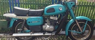
If you look at the photo of the Voskhod motorcycle, we will see a simple workhorse that is great for riding on different road surfaces . The bike's engine is equipped with improved cylinders and modified crankcases. The vehicle body was also slightly modernized.
On the road, the Voskhod motorcycle behaves very reliably and confidently, thanks to which it has earned the status of a reliable iron horse. At the same time, the model maintains its stability even with changes in speed.
Such a vehicle is also pleased with its good dynamics - the maximum speed is reached quite quickly. To accelerate to 60 km/h, the bike takes only 8 seconds
Cool video about a motorcycle from the past Voskhod 2:
Motorcycle VoskhodAll photos Voskhod 2, 2M, 3. Multicolor album (catalog).66
Sunrise 2, Sunrise 2M, Sunrise 3 Download link: https://vk.com/doc-21535744_415416179
66 photos|Comments to the album
Show more photos
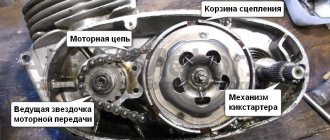
Assembly
I won’t rant too much on the topic of assembly since assembly is done in the reverse order of disassembly. I will dwell only on the most important points.
We put the sprocket on the crankshaft journal and tighten the nut; we put adjusting washers on the gearbox shaft and then put the basket there along with the spacer sleeve; position the engine relative to yourself so that you can clearly see how aligned the teeth of the motor chain sprockets are relative to each other
In my case, the misalignment of the teeth was about 7 mm. The norm is within a millimeter. For clarity, I attached a ruler to the star. If you have the same situation with the alignment of the teeth, place adjusting washers under the spacer sleeve until the teeth are exactly opposite each other. If this point is neglected, the chain will work skewed, and this will lead to rapid wear of both the chain itself and the teeth of the basket and sprocket.
After installing two additional shims, the tooth misalignment situation was completely resolved.
We install the clutch parts in their places, tighten the nuts and secure them with washers.
We look for the thickest one among the metal disks and install it on the inner drum - with the chamfer facing the engine.
Caring for a sunrise motorcycle generator - how to remove, what to check and install correctly
Generator maintenance mainly comes down to tightening the threaded fasteners of the generator stator and rotor, as well as the wire terminals.
In order to remove the generator, you must:
- disconnect the wires of the ignition circuit, sensor, brake light and direction indicators from the generator terminals;
- unscrew the three screws securing the stator to the crankcase and remove the stator;
- Unscrew the bolt securing the generator rotor and, with light, careful blows of a wooden hammer on opposite sides of the rotor, remove it from the trunnion and remove the key.
Checking the removed parts
After removing the generator stator and rotor, wash the parts with clean gasoline and carefully inspect them. Disassemble the wire fastening terminals on the stator. Wipe dry all insulating parts of the terminals.
Generator installation
Installation is carried out in the reverse order, in this case it is necessary:
- check the runout of the generator rotor, which should be no more than 0.1 mm with the bolt secured;
- tighten the generator stator without distortions, ensuring a tight fit to all three supports;
- install the ignition correctly;
- The generator wires must be securely fastened and well insulated from each other.
Supply system
To make the bike go faster, you need to adjust the original carburetor for a higher fuel supply or replace it with a more efficient one. To install a new carburetor, you need to perform the following steps:
- we grind aluminum bushings under the flange of the pipe attaching the carburetor to the cylinders;
- cut off the edge of the inlet channel;
- take a flange from an old carburetor;
- We fasten all the elements using cold welding.
The assembled carburetor must line up exactly with the intake port.
Switch Voskhod – electronic KET-1
The electronic switch KET-1 is designed to work in the ignition system complete with the G-427 generator and the B-300B high-voltage transformer. Allows you to obtain a secondary voltage of up to 18 kV, at a generator rotor speed of 250 to 7500 rpm. The switch is installed in the right toolbox. The base of the commutator is connected to the ground of the motorcycle. If the switch fails, it can be disassembled and repaired
Ignition adjustment Voskhod
The ignition timing is set by turning the generator stator after first loosening the three screws securing the stator to the crankcase. For normal engine operation, it is necessary that the moment of spark formation (on the generator, this moment is determined by the coincidence of the sensor rotor groove with the protrusion on the sensor coil frame. Fig.) coincides with the moment when the piston does not reach the top dead center of 2.5-3.0 mm (at running the engine on gasoline with an octane rating of 92).
The gap between the rotor and the core of the sensor coil should be within 0.3±0.05mm.
The gap should be set as follows:
For more accurate ignition installation, it is recommended to determine the piston position with the cylinder head removed.
The electronic switch KET-1 is designed to work in the ignition system complete with the G-427 generator and the B-300B high-voltage transformer. Allows you to obtain a secondary voltage of up to 18 kV, at a generator rotor speed of 250 to 7500 rpm. The switch is installed in the right toolbox. The base of the commutator is connected to the ground of the motorcycle. If the switch fails, it can be disassembled and repaired
The electronic switch has three output terminals with letter markings on the body >, > and >. The ground terminal is the base of the switch.
Maintaining the switch during operation comes down mainly to tightening the threaded connections, while avoiding stripping the threads. It is necessary to protect the switch from moisture getting inside it and onto the terminals from sudden shocks and exposure to high temperatures. You should also systematically check the reliability of the electrical connection of the switch base with >, because If this condition is violated, sparking on the spark plug stops.
Engine and possible breakdowns
The Voskhod 3m engine is a two-stroke, single-cylinder carburetor. The working volume of the cylinder is no more than 173.7 cm3. Piston diameter/stroke – 62/57.6mm. Engine power is 15 hp. A used engine in working condition can be purchased for 2000-4000 rubles.
The sore point of all Voskhod 3m is the rapid burnout of the bobbins, which have to be changed with constant use of the motorcycle, about 4 times a year. The chain tensioner also requires constant replacement - with aggressive driving it quickly breaks down. As for the engine, all the troubles that may arise with it are related to the piston. Installing new rings or completely replacing the piston solves most problems.
Spark plug Voskhod - spark ignition type A-23
During operation, the spark plug must be periodically cleaned of carbon deposits and the gap between the electrodes must be adjusted, which should be within 0.6-0.7 mm, which is ensured by bending the outer electrode. To seal, a copper-asbestos gasket is placed between the spark plug and the cylinder head. To eliminate radio interference created by the ignition system, a shielded tip of type A-4 is placed on the spark plug.
REPAIR OF MOTORCYCLE IGNITION SWITCHES
More than two years have passed since I installed contactless ignition on my Izh-Jupiter 4 motorcycle based on a Voskhod generator, switch 262 3734 and a homemade diode mixer (Fig. 1.).
Having convinced myself of the reliable operation of my creation, my colleagues decided to make a similar improvement to their motorcycle equipment. However, questions like “I assembled it according to your scheme - explain why it doesn’t work for me” arose. Here are some typical faults:
— no spark at all;
— the engine works well at idle, but fails at speeds above average;
- the engine starts well, but mainly one cylinder works, the second one picks up occasionally, the flashes follow unevenly,
- there is no spark only when installed in the Izha circuit - on Voskhod there is a spark, when replacing the switch-stabilizer unit (BKS) with a similar one of a different type (251 3734 on KET 1-A), the fault disappears.
All of the above troubles indicate a defect in the BCS. Let's look at the factory diagram of the block (Fig. 2.). It is copied from the KET 1-A block produced in the 1980s. In terms of switches, the VD2 zener diode is represented by KS650 (or two D817B connected in series). The latest versions of BKS - 251 3734, 261 3734, 262 3734 are not schematically different. Only the appearance and type of some parts have changed.
Rice. 1. Non-contact ignition based on a Voskhod generator, switch 262.3734 and a homemade diode mixer
Rice. 2. Schematic diagram of a factory-produced switch-stabilizer (BKS) unit
Rice. 3. Scheme for checking capacitors and thyristors for leaks
Rice. 4. Diagram of the device for selecting thyristors VS1
The operating principle of the devices is the same: capacitor C2 is charged from the high-voltage winding of the generator along the circuit VD1, C1, VD2, VD4, R2. With a positive voltage pulse from the transmitter, the thyristor VS1 opens through VD3, which discharges C2 onto the winding of the ignition coil TV1, forming a spark on the spark plug F1. Zener diode VD2 limits the voltage on C2VS1 at 130 - 160 V. However, on a working switch, the voltmeter showed 194 V - an obvious overvoltage, the influence of the spread in the parameters of the zener diode. I would like to note an interesting detail - two MBM type capacitors were used as C2. Such capacitors can operate in pulse mode for a long time. Being “self-healing”, they easily tolerate short-term overvoltages. The breakdown areas of the plates are filled with paraffin impregnation of the dielectric. Unfortunately, this does not go away without leaving a trace - over time, the foil coverings begin to resemble a sieve, and the capacity of the device decreases. Dielectric breakdowns lead to an increase in conductivity and the appearance of leaks. When working in a switch, such a capacitor simply does not have time to accumulate charge during the time between two sensor pulses. This is why the unit that works normally on Voskhod (Minsk) malfunctions in the Izha circuit, where the frequency of the trigger pulses is twice as high.
A leaky capacitor is identified using a simple diagram (Fig. 3). In compliance with safety measures (the circuit is galvanically connected to the household network), we connect the capacitor being tested into the circuit. The indicator lamp should not light up - the glow indicates the presence of a leak. Check time is 15 - 30 minutes (in doubtful cases - up to 1 hour). Despite the somewhat barbaric method of testing, it is practically safe for the capacitor. During operation, it is subjected to heavy loads. Thus, I identified thirteen capacitors with obvious leaks, four of them in blocks that worked normally on single-cylinder engines, but failed in the Izha circuit. Replacing capacitors in KET-1A is not difficult - the unit can be easily disassembled. The same replacement in version 252.3734 is more difficult. First, remove the porous mass filling the housing by boiling the switch in boiling water for 15 - 20 minutes. Then we carefully pluck out the filler with tweezers. By pulling the connectors, we remove the board and gain access to the printed circuit board. You can, of course, replace a faulty device with a similar one, but there is no guarantee that the new one will not fail soon either (see the reason above), so I recommend replacing it with capacitors like K73-17 1.0 μF/ 400 V (or even better, 4x0.47 μF/ 630V). Two capacitors are normally located on the board. We seal the block by filling it with construction foam or a rubber plate cut to size. I would warn you against using various auto sealants - their active components will eventually destroy the copper traces of the board. In order to ensure maximum reliability of the device, I consider metal-paper capacitors of the MBG, MBGP, MBGCh types (the letter G indicates the design of the device), designed for a voltage of 400 - 630 V, as a “no alternative” option. The only problem in this case is the dimensions. A compromise option in the circuit for “Izh-Yu” is possible: we reduce the value of C2 to 1 μF. This will ensure its guaranteed charge in half a revolution of the crankshaft.
The remaining elements of the device usually do not cause any particular complaints. S1 (K73-15) is quite reliable. I advise you to replace diodes VD1, VD4 with KD226G (with a yellow ring) VD3 is practically “indestructible”. It happens that the VS1 thyristor changes its characteristics (the engine starts to start in the opposite direction) - this can be eliminated by replacing it with a KU202N or (even better) with a T122-20-10. It is extremely rare for KU221G (KU240A1) to fail. Replacing the SCR involves selecting the minimum control current. This ignition circuit is very demanding on this parameter. I carry out the selection using the circuit shown in Figure 4. Moving the R1 slider from bottom to top, we use the milliammeter PA1 to note the opening current of the test SCR VS1 at the beginning of the glow of the EL1 lamp. For use, we select specimens with a control current I = 1 - 8mA. Unfortunately, there are SCRs with increased leakage current. This parameter is checked according to the diagram shown in Figure 3. The glow of the lamp will indicate a malfunction of the device.
The BKS restored in this way is suitable for further use in the ignition system of both single- and two-cylinder motorcycles.
D. RASKAZOV, Kashira
We recommend reading
- MODEL CONSTRUCTION 1981-04 CONTENTS: Decisions of the XXVI Congress of the CPSU - put into practice!: Concern is common! (1). NTTM: organization and methodology: N. Grishechko, A. Teplitsky. The topic of the lesson is invention (3). Stages of the long journey:...
- OUTLET WITH A COVER In an apartment where there are small children, ordinary sockets pose a great danger to them: two holes are very attractive to children - you just want to stick something in them. From…
Owner reviews
Screenshot of review No. 1
Screenshot of review No. 2
Screenshot of review No. 3
Screenshot of review No. 4
Screenshot of review no. 5
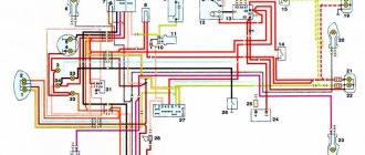
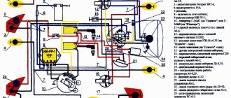
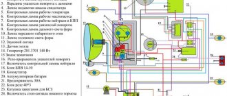
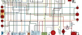
Electrical circuit of the Voskhod motorcycle
Central switch. 2. speedometer. 3. Speedometer light. 4. Headlight. 5. Headlight lamp. 6. City driving lamp. 7. Sound signal. 8. Direction indicator lamp. 9. Direction indicators. 10. Direction indicator switch. 11. Electronic switch. (D – sensor terminal, K – ignition coil terminal, G – generator terminal.) 12. Throttle. 13. Relay breaker. 14. Generator. 15. License plate lamp. 16. Brake signal lamp. 17. Rear light. 18. Wire connection block. 19. Brake light switch. 20. Shielded spark plug cap. 21. Spark plug. 22. High voltage wire. 23. Ignition coil. 24. Light switch.
Specifications
- Dimensions: 2000x1200x850 mm – length, height and width, respectively
- Weight: 122 kg
- Engine power 15 hp
- Gasoline consumption 4.2 liters per 100 km in mixed mode, tank volume 14 liters
- Gearbox – 4-speed with mechanical gear shifting
- Ground clearance 125 mm
- Maximum speed 105 km/h
Basic data | |
| Length Width Height | 2000/ 850/ 1200 |
| Base, mm, no more | 1300 |
| Ground clearance, mm, no more | 125 |
| Weight of the equipped motorcycle, kg, no more | 135 |
| Load capacity, kg no more | 160 |
Dynamics and efficiency | |
| Maximum speed, km/h, not less | 105 |
| Fuel consumption | 4.2l/100 km |
| Fuel tank capacity | 14 |
Engine | |
| Type, timing | carburetor, two-stroke |
| Number of cylinders | 1 |
| Working volume, cm3no more | 173.7 |
| Bore/stroke | 62/57.6mm |
| Maximum power, kW (hp), not less | 14 (15) |
| Carburetor | K65 V |
Transmission | |
| Clutch | multi-disc in oil bath |
| Clutch control | manual |
| Gear shift | foot |
| Motor transmission | single row bushing chain |
| Reverse gear | single row roller chain |
Gear ratios | |
| Motor transmission | 2.07 |
| Transmission | 1- 3.04; 2- 1.99; 3- 1.34; 4- 1.00; |
| Rear wheel transmission | 31809 |
Chassis | |
| Frame | tubular, closed, single |
| Suspension travel along the wheel axes, front/rear, mm, not less | 160/80 |
| Brakes | drum with mechanical drive |
| Wheels | spoked |
| Tire size | front 3.25-16 or 3.50-16, rear 3.25-16 or 3.50-16 |