While easily fixing mechanical failures, motorcyclists experience difficulties if the electrics fail. It’s completely in vain, the wiring diagram of the planet Izh 5 is not complicated, it’s easy to figure out.
There is no need to have special stands and equipment for repairs. A minimum knowledge of electrical engineering and a simple avometer (tester) is enough; even often you can get by with just a test lamp.
We will tell you in more detail about the main electrical wiring components and possible malfunctions. The Izh Planet wiring diagram makes it easy to find a broken wire or damaged insulation (for example, a bad contact always gets hot).
But pay special attention to the fact that the electrical circuit is designed not only for 12 volts, there is also a high-voltage cable (connecting the coil and the spark plug), which cannot be checked with a regular ohmmeter.
In this case, we look to see if there is a spark at the coil output and at the output at the spark plug contact. Let's take a closer look at the main wiring components of the Izh Planet.
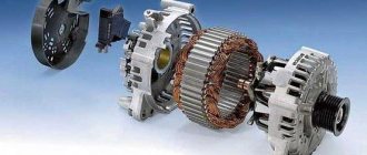
Generator
The heart is the generator (sometimes called a magneto, but they were never used on Izh Planet). Three windings produce alternating current. For excitation, an additional coil is used instead of a permanent magnet. Therefore, it is impossible to jump start a motorcycle with a completely dead or missing battery.
A diode bridge for current rectification and a voltage regulator assembled in one unit are mounted on the Izh Planet 5 generator (they are not even highlighted in the Izh Planet wiring diagram manuals).
Possible breakdowns in this unit:
- Breakdown or breakage of coils. It is checked by measuring their resistance of current-carrying conductors and insulation. If the generator is damaged, it will become noticeably hot.
- Failure of the diode bridge - the output voltage will differ significantly from the nominal level or be absent.
- Failure of the voltage regulator. Although the electrical circuit includes short circuit protection, it happens that the automation does not work and most often the output transistor burns out.
Army and weapons
I have been repeatedly asked to share my experience in installing a BSZ, a diode bridge and a relay regulator. I did this as much as possible, until they began to insist that I break out in an article where I could explain everything in an accessible way. The whole difficulty lies in the fact that after these installations I long ago moved towards reworking the Izh-Yunker electrical circuit. And today, reproducing exactly how it actually was on a motorcycle is quite problematic, and even more so since the wire connection points and their colors on any electrical circuits differ from the factory ones, including the fact that I encountered the fact that on different motorcycles (Izh - Juncker) the same wires are different in color.. Therefore, I will not tell you the specific color of the wire and tie it to the diagram, but I will name the wires according to their functionality, for example: “this wire goes to the left rear marker,” and you you will have to recognize it in practice, which, by the way, is very useful for experience. I won’t describe the advantages of this or that device or the advantages of this or that method, everyone chooses shoes according to their feet, I’ll just try to present them in a way that is simple and understandable.Required spare parts and materials:
- Relay – regulator 2101, 2106.
- Generator diode bridge (suitable for VAZ and GAZ generators.
- Capacitor for diode bridges (in my opinion, all are the same for VAZ and GAZ)
- 2 spark plugs from GAZ with electronic ignition system.
- 2 short high-voltage silicone wires (I bought them for fifty dollars from some garage cop)
- The ignition coil (VAZ 1111, GAZ with engine 406) is two-terminal, dry.
- Switch (VAZ 2108)
- Hall sensor (VAZ 2108)
- Connection blocks for switch and Hall sensor.
- Heat-shrinkable cambric 8 - 2 meters.
- Set of male-female and ring terminals.
- Installation wire 1.5 square - 2.3 meters.
- In addition to the standard tool, you will need a radio crimp (you can try using pliers).
- Metal scissors.
- Sheet metal 0.8-1 mm thick 10x10 cm (I used regular galvanized steel 0.7 mm, but many recommend transformer steel, in my opinion, the higher the magnetic properties of the metal, the better, for example, case steel gave me a disgusting spark)
- Screws and nuts M3 and M4.
1. This is, of course, dismantling the standard system.
A. For relay regulator:
The battery charge control system includes a standard BPV and what I would call a generator rotor. From the BPV, 2 wires supply voltage to the rotor through the carbon brushes. One brush wire (-) is connected to the top of the BPV and it should be black. The second wire should be red (+) connected on the lower right side of the BPV. Feel free to take them off. Now you have to bend over to the generator. Since the relay-regulator used controls the current on the rotor through (+), I do the following manipulations. Plastic blocks are installed on the generator housing, which allow you to isolate the wire connections from the housing - “b”. We find the connection between the white brush wire and the short wire with the black wire and release the brush wire (we unscrew the nut on M3, if I’m not mistaken, with a key on 5). There is a 3mm terminal mounted on it, I drill it out (ordinarily with the tip of a knife) to 4mm. And now I put this terminal on the mounting screws of the block itself and tighten it,
thereby applying (-) – “a” to the brush. By this action I get 2 advantages, 1 – I free one wire in the harness from the top of the wiring to the generator (it is enclosed in a black cambric), 2 – I reduce the resistance in the rr-rotor circuit, albeit slightly, but I reduce it. In my opinion, with such a generator, every half of a tenth of a volt is relevant, the economy should be economical.
b. For a diode bridge from VAZ, GAZ:
Easier than steamed turnips. On the BPV there are black (some have brown and God knows what other color it might be) wires (-) on the lower left part of the BPV and red (and there may also be one light blue, dark blue, etc.) wires (+) on the middle lower part of the GSV. And three pink ones (can be purple, gray, etc.) on the right side of the GSV. I free the black ones and twist them with any available twist so that they do not crawl into the cracks, and I do the same with the red ones. And I remove the pink ones (they come from the generator from each phase and supply alternating current from each phase, of which there are only three) and leave them as is, anyway they have nowhere to go.
V. For the ignition system:
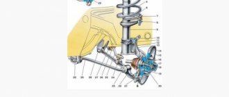
I hope you've already dropped your tanks. Now you have a complete picture - 2 ignition coils hanging under the frame and a contact group on the generator body. First of all, we say goodbye to spark plugs, high-voltage wires, and spark plug caps with a built-in resistor; they will never be needed again. Moreover, I happily said goodbye to the caps, which tend to burn out while maintaining the appearance intact, and then you worry and look for the reason for the lack of a spark on the candle. Now we have to strain our memory and remember which wires we remove from the reels. The first one should be red with an intermediate terminal - this is the (+) one suitable for the coils. The second and third - pink (purple, etc.) go to both reels. these are the “stop - engine” wires, now pay attention: the fourth is green (light green, i.e. green), goes to the contact group, the fifth is yellow (orange, light red), goes to the contact group, and finally the sixth - another one red one goes to the radiator fan switch on sensor. REMEMBER. and the latter are brown, these are always sitting on (-) or on the ground (you can take an adhesive plaster, cut off pieces, sign with a regular ballpoint pen and stick on each wire). Now we remove the ignition coils, but keep one of the coil clamps and straighten it, it will be useful later. On the generator body, remove the contact group and capacitors. From each contact hammer there is a wire to the above-mentioned block. We unscrew the nuts on the M3 and finally free the contact group, as well as two wires - green (i.e. green, light green) and yellow (orange, light red), these are the same wires that I called on the ignition coils No. 4 and 5. Then I disassembled the contact group, cleared the platform, and later on its base I will mount a Hall Sensor (hereinafter referred to as DH). And finally, about how to prepare the rotor axis for installing the rotor generator. I unscrewed the rotor bolt with an 11-socket Metrinch wrench, these tools even twist broken heads. But if you only have an 11 horn, don't even try to touch the bolt. I recommend using a head with a knob set to 11. We install the head on the bolt, having first engaged 1st gear, and with a sharp blow to the knob we turn off the bolt. If this is not enough, then before doing so, hit the head of the bolt with a hammer. There you just need to squander the grower, just. I use a different method, take a more powerful screwdriver, feel for the “beak” (a metal core similar to a beak) of the rotor in the round hole of the generator stator and use the screwdriver lever to fix the rotor, and with the head I calmly pull off the bolt.
That's all the preparatory work. You can begin installation.
Installation of systems.
A. For relay-regulator:
Everything is simple to the point of banality. I take (+) anywhere after the ignition key. You can put the “mother” terminal on the red wire that went to the ignition coils. However, if you use it, we do it this way: Cut off the ring terminal from the red (+) wire from the ignition coil and add to it another end of the mounting wire, preferably also red, so as not to get confused later, about 35 cm long (1 terminal - 2 ends of the wire), I crimp the terminal, put a piece of heat-shrinkable casing on top of the terminal and heat it with a regular lighter. The casing will fit the terminal and the wire tightly enough and if it ever jumps out, a short circuit will not occur. This terminal will go to the groove size No. 15 “a”.
I take the wire (+) of the brush, it is near the right tank, if you remember, we removed it from the lower right part of the BPV, and in my opinion there is already a “mother” terminal there, if not, then install it. And again, the shrink casing rules. This is the wire for terminal size No. 67 “b”. We take the solution and connect it. Later, when you hang the tanks, screw it to the lower ear (next to the saddle) of the left tank to ground “b”. Under no circumstances should you start the engine without securing the solution to ground (tank fastening), otherwise the solution will either burn out or change the current control parameters. Although I already burned 4-5 of them, forgetting to screw them to ground. By the way, don’t worry about the (-) brush, we’ve already screwed it onto the (-). The voltage should now rise. I can only add that, like all products, the solution may be of low quality and the variation in parameters is significant. It is quite likely that you will come across a leftist, so we do not throw away receipts and change them. Now, when starting the engine, the voltage at the battery terminals should be at least 12.4V (if the stator and rotor are normal, i.e. the generator is working!).
b. For a diode bridge:
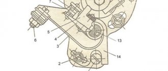
We take the “horseshoe” of the bridge in our hands and see round diodes on it. The “horseshoe” itself (hereinafter simply the horseshoe) of the diode bridge consists of two plates, one of them (+) is “e”, the other (-) is “g” and they are insulated from each other, the plate that has insulation on the mounting hole (at the end) is (+). There is a second way to determine which of the plates is positive, but only after assembling the BSZ: we connect the same three pink “a” wires (purple, gray) that come from the generator, hold them in our hands or place them on the insulator, start the engine and measure the voltage between the two plates horseshoes. I hope it’s now clear which of them is (+) (here I got ahead a little; I’ll tell you below how I organized the connection of 3 phases of the generator). Now you need to cut out the metal corner “b”, I cut the ignition coil from the clamp. Drill holes in it for fastening to the upper left frame bracket from under the BPV and directly to the (-) horseshoe plate – “b” (it has a mounting hole at the end of the plate). Now I can prepare to switch on 3 phases of the generator. You will need 3 pieces of mounting wire, 2-5cm each - “a”. I crimp the ring terminal to 4 on one end - “f”, on the other end I crimp the “male” terminal and with these pieces I can connect to the existing wiring. All. We connect the red wires (+) to plate “B”, I already have one wire. And we connect the black and brown ones to ground (-) “b”. The diode bridge is connected.
The first thing I do is cut out a rectangle “a” with dimensions of 6.5x2.5 mm from ordinary galvanized steel (preferably 0.9-1 mm thick), at the point of intersection of the diagonals (center) with a core and drill an 8 mm hole.
I did not buy harnesses, connectors for connecting devices. Therefore, I will use 3 wires freed from the old ignition system and 1 wire from the brush to connect the DH. You can even roughly match the colors of the wires. Those. green to green, black to black, and orange from DH to red - position “c”.
Now I cut everything off the old contact plate and attach the DH to it (not difficult, just 2 m3x15 screws and 4 m3 nuts). Now, if I replace the DH, I pull it out of the block, unscrew it from the plate and replace it. You can immediately install the ignition. I use a regular standard device. Instead of a spark plug, I screw it onto the right boiler and set the advance on it to 2.3mm.
I hang 1 voltmeter probe on the middle contact of the DH - “g”, the 2nd one on ground. I turn on the ignition switch. I turn the curtain on the central bolt clockwise until the voltmeter shows me “0” - “d”. A more accurate position is not just “0”, but the moment when “0” appears. All that remains is to tighten the bolt, but do not pull out the voltmeter yet. I tighten it in this way: I feel with the tip of a screwdriver through the hole in the stator for the “beak” of the rotor – “b”, I push it and, holding the curtain with my finger, I tighten the bolt (remember school gymnastics).
Tightened it up. But anyway, while I was tightening it, I shifted the position of the curtain. This means I turn on the ignition again, loosen the screws securing the plate with the DH and begin turning it counterclockwise until “0” appears. That's it, the ignition is turned to zero!
Let's go upstairs. The switch installs very well on the receiver box. I drill in place, 2 auto-tapping screws and screw the switch to the receiver - “a”. Here he is dry and not hot. And the switch radiator is screwed to the hardware, additional cooling. And under one of the screws I attach a pre-prepared wiring, which has a ring terminal on one side and a male terminal on the other. This will be (-) for the switch.
Now the ignition coil.
We take the clamp from the old coil “a”, straighten it, mark the mounting holes in the place of the new coil, and secure it “b”. We bend the remaining wings to the angle of the previous fastening on the frame and fasten them to the frame “g”.
The main components have been installed. Well, install the spark plugs and high-voltage wires yourself.
Now we move on to connecting the wires into the harnesses. We extend the red wire with the intermediate terminal (+) with wires, 1 piece with the “female” terminal for the coil, 2 pieces with the “female” terminal for the rr, pull the 3rd piece to the positive wire of the switch, contact No. 4. Negative wire from under the screw to No. 2. Separately, we make a wire from the switch, contact No. 1, to the coil, crimp the “mother” terminal on one end, the other will be used for twisting and heat-shrinkable casing. There are 3 wires left from the DC. We look at the harness that goes from below, and remember: green on No. 5, orange on No. 3 and black on No. 6 and make twists under the heat-shrinkable casing according to the diagram. Then I simply assembled the whole thing into corrugated hoses “a”.
So what are you waiting for? Let's start!
If suddenly, when closing the chrome cover of the right side of the crankcase, the engine stalls, then simply swap the (+) and (-) brushes. Please note that the generator brushes are rectangular in cross-section!
PS Off topic, but I’ll add: very often many people make mistakes about the ovality of stars. To begin with, I suggest you make sure of the more likely case: is your input shaft bent? We look at the center “a” of the sprocket and start the engine. The center should be in place, and the star should not write a circle.
By the way, when I adjust a semi-automatic machine, I simply orient the fork of the semi-automatic machine exclusively towards this point. And the entire adjustment procedure is simplified.
For those who are interested, I can add an integrated circuit diagram. It will be easy to implement together with a diode bridge. Advantages: finer settings for excitation current to the rotor and, as a result, a more even characteristic of voltage and current in the on-board electrical circuit. Cons: drag an additional wire from the bridge to the solution or to the brush, depending on where the solution is located and the need to insulate the solution.
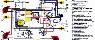
I am attaching diagrams of the standard electrical circuit and modifications:
List of required parts:
1. Diode bridge generator BPV 56-65-02-G (“with one wire”) or BPV 56-65-01 (“with two wires”).
2. Voltage regulator Y212A11.
3. 100 ohm resistor with a power of 1 Watt. (Not required)
Diode bridge BPV56-65-02-G
Note
: the difference between BPV 56-65-02-G and BPV 56-65-01 is that the first has a male connector made in the housing (and we will have to break it out and solder a wire instead), while the second diode bridge has it made in the form of an additional wire.
Voltage regulator YA212A11
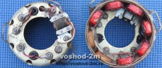
Installing a horseshoe on a generator:
We take the generator and remove everything unnecessary from it:
Next we need to cut out a place to become a horseshoe, leaving an uncut part in the middle for the rigidity of the structure:
Then we need to extend the stator wires. It is not necessary to remove the stator from the generator housing, it will just be more convenient to solder, and it will be convenient to carefully insulate it.
Now you need to cut off the excess from the horseshoe so that it fits normally into the cut out generator housing and when the right cover is installed there is no short piece of the top plate with the inner wall of the cover. Break off the terminal (male connector) that sticks down. Also replace the inner plate (to which small diodes are soldered) with a wire, in case there is also no shorty with the generator body:
Next, you need to attach the horseshoe to the generator. To do this, we drill holes for the bolts on the horseshoe opposite the threaded holes on the generator, and make a larger hole in the top plate so that the head of the bolt can fit through. So that when we clamp the bolt, it does not touch the top plate (Don’t forget that this is + and it should not short-circuit with mass anywhere!):
And at the same time, do not forget to place an asbestos gasket under the diode bridge so that the diodes do not heat up from the generator, since they do not like overheating.
Now that we have secured the horseshoe, we can solder three pre-extended wires from the generator in these places, no matter in what order:
The first thing we need to do is cut off the lower collar on the regulator (the figure below circles what needs to be cut) so that the brushes are hidden as much as possible in the regulator body and so that they are normally pressed against the armature current collectors. If this is not done, then they may break off or they will have difficulty reaching the anchor:
You will have to cut just to the bottom hole, and make a new one a little higher. And the thing is that there is a mass of regulator going to the lower hole at the back, so you will need to carefully bend it:
Next we need to make J-shaped mounts to which the regulator will be screwed:
You also need to cut off the corner of the plate on the regulator so that it does not touch the generator housing:
So, there is nothing special about the connection... The top plate turns out to be the output +
, that is, from which charging is already taking place.
We drill a hole in it on the left side and screw the wire, we connect it directly to the battery, soldering it to the wire that goes to the +
battery.
The bottom plate, accordingly, is
(mass), and, in fact, we already have it bolted to the generator.
We insert the red wire with the connector into the regulator, and also do not forget to connect the ground of the regulator. And in the place where the red wire is soldered, we solder another wire ( if you have a BPV 56-65-01 , then there is no need to solder the wire, since it is already soldered
), it goes to the generator control lamp, also parallel to the lamp you need to solder in a shunt resistor (it is primarily intended if the lamp suddenly burns out, so that charging does not disappear)
100 ohms
with a power of 1 watt, in principle this is not necessary, for the first time you can do without it, the main thing is that the lamp has more watts. We connect the other wire from the lamp to the ignition switch. Well, at the top I wrote where the generator phases are soldered to the horseshoe. All. That's all the connection is.
Didn't find what you were looking for? Use the search:
Best sayings:
For students, there are even, odd and test weeks.
9438 – | 7438 – or read all.
91.146.8.87 © studopedia.ru Not the author of the materials posted. But it provides free use. Is there a copyright violation? Write to us | Feedback.
Disable adBlock! and refresh the page (F5)
very necessary
I have in my garage my “Old Friend” IZH Yu-5, which was given to me when I graduated from school! The only owner of which is only me. I haven’t driven it for a long time, more than 10 years, and it wouldn’t start, there was no charging, constant problems with the cams and dead ignition coils, and of course the right pot! It's time to revive your comrade! It was decided to install the BSZ, do normal charging with car elements and replace the wiring! I go to the store and buy parts:
1. Relay - regulator 2101, 2106. 2. Generator diode bridge (suitable for VAZ and GAZ generators. 3. Capacitor for diode bridges (in my opinion, they are all the same for VAZ and GAZ) 4. 2 spark plugs from GAZ with an electronic ignition system. 5 . 2 short high-voltage silicone wires (I bought it for fifty dollars in some garage cop) 6. Ignition coil (VAZ 1111, GAZ with engine 406) two-terminal, dry 7. Switch (VAZ 2108) 8. Hall sensor (VAZ 2108) 9. Connecting blocks for the switch and the Hall sensor 10. Emergency ignition (just in case) 11. Terminals, wires, electrical tape and nut - I think everyone has them in the garage 12. I ordered a modulator plate and a hall sensor mounting plate on the Internet to sharpen myself it was a mess))
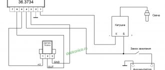
Installing the BSZ 1. Remove the breaker contacts, coil, capacitor and all other crap from the contact ignition. 2. We put the switch in the right glove compartment, the coil under the tank. 3. Unscrew the generator bolt. 4. Install the modulator. 5.Attach the Hall sensor. 5.1. We fasten the modulator, but do not tighten it! 6.We connect everything according to the following scheme. Save to Album Diagram 1 Diagram 1
7. We put the armor wire on the spark plug and connect it to the coil. Everything is done according to the first scheme, everything is done in an elementary way and in terms of time you can do it in an hour with smoke breaks. 8. Connect the ignition coil. Save to Album 2 color scheme 2 color scheme
The ignition is set simply: the piston is at TDC further 3.5 mm back and for the convenience of finding the moment of the spark, an instant diagnostic unit “MD-1” was purchased
Next, we are engaged in charging 1. We throw out all the elements of the old charging system 2. Brushes. Since the relay-regulator used controls the current on the rotor through (+), you need to do the following. Plastic blocks are installed on the generator housing, which allow you to isolate the wire connections from the housing. We find the connection between the white brush wire and the short wire with the black wire and release the brush wire (unscrew the nut on M3). There is a 3mm terminal mounted on it, we drill it out to 4mm. And now we put this terminal on the mounting screws of the block itself and tighten it, thereby applying it to the brush (-). 3. Diode bridge. On the BPV, black wires (-) go to the lower left part of the BPV and red wires (+) to the middle lower part of the BPV. And three pink ones on the right side of the GSV. We release the black ones and twist them, and we do the same with the red ones. And we remove the pink ones (they come from the generator from each phase and supply alternating current from each phase, of which there are only three) and leave them as is. The diode bridge consists of two plates, one of them is (+), the other (-) and they are insulated from each other, the plate that has insulation on the mounting hole (at the end) is (+). We connect the red wires (+) to plate. And we connect the black and brown ones to ground (-). The diode bridge is connected. 4. Relay regulator. Take (+) anywhere after the ignition key. This terminal will go to the groove size No. 15. We take the wire (+) of the brush, it was removed from the lower right part of the BPV, this is the wire for terminal size No. 67. We take the solution and connect it. Next, we screw the solution to ground; you can’t start it without this, otherwise it will burn out! 5. To make sure the charging light on the dashboard goes out, run it through the relay.
Battery
The battery in the motorcycle is low-power. The motorcycle does not have a starter, so its task is only to supply voltage to the ignition system and the generator excitation winding during starting. Thanks to the battery, designed for 12 volts, a stable start of the fifth Planet is ensured; up to the third model, the wiring was 6 volt, and the ignition was not always clear.
Possible battery malfunctions:
- Mechanical damage - housing, plates, leakage of electrolyte.
- Loss of electrolyte density is determined by measurements using a hydrometer.
- The short circuit of the plates in the banks is detected by measuring the resistance.
- It is possible that the connection is not correct, minus not on the body (frame) of the motorcycle - all the electronics will not work.
Maintenance
Those who love their bike regularly monitor its technical condition. During operation, it is sometimes necessary to adjust the gap between the breaker contacts. To carry out this operation, you need an electrical diagram of the IZH 5 motorcycle, which shows the connection of devices, and the corresponding tools.
The procedure consists of the following steps:
- The motorcycle should be placed on the stand and put in neutral.
- Next you need to unscrew the spark plugs.
- Then remove the cover from the crankcase.
- At the next stage, you need to ensure that the contacts are as open as possible. To do this, we need to turn the crankshaft.
- Next, you need to loosen the locking screw using a screwdriver.
- Using a feeler gauge, the gap should be set to 0.35-0.45 mm. Fix the gap with a screw.
- We do the assembly in reverse order.
When the clearance is correctly set, the engine idles stably.
The electrical circuit of IZH 3, 4, 5 and 6 is quite simple and any driver can figure it out in order to repair it with his own hands if necessary.
This need may arise in the following cases:
- operating the bike in wet weather (contacts oxidize);
- movement through areas overgrown with vegetation (mechanical damage to wiring);
- trips in winter (dirt sticks, which can damage the wiring).
On both IZH 5 and 6 bikes there may be problems with the sound signal; it may sound weaker. To adjust it, you need to loosen the lock nut, turn on the ignition and use a screwdriver to adjust the tone. Once the desired tone is achieved, the locknut must be tightened.
Source
Ignition system
The ignition chopper is used to ignite a spark at a certain point in the piston stroke. In early modifications of the electrical wiring of Izh Planet 5, contact was mounted, later electronic.
The main malfunctions of this unit:
- Burning of breaker contacts is determined visually.
- Failure of a sensor or switch elements - the easiest way to detect it is to use the method of installing a known-good unit. The lubrication system sensor valve is also checked using the same method.
- An incorrectly set ignition timing is visible from the fuzzy operation of the engine. It can be eliminated by adjustment using special probes.
The ignition coil increases the voltage to several kilovolts so that the discharge can ignite a spark at the spark plug electrodes. The secondary winding is made of a fairly thin wire; most often it burns out. Although a breakdown between the turns or onto the housing is also possible. The same troubles can (but less often) happen to the primary circuit. Everything is revealed using resistance measurements.
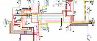
Wiring diagram IZH Planet 5
Detailed color wiring diagram for motorcycle IZH Planet 5
Explanations for the diagram
The numbers on the electrical diagram correspond to the following elements:
- Light switch, dimensions/low.
- Light switch, direction indicators and horn buttons.
- Front turn signals.
- Instrument panel lighting.
- Indicator lamp for generator operation.
- Oil pump operation indicator.
- A light indicating the operation of the neutral gear in the gearbox.
- Direction indicators.
- High beam headlight indicator.
- Front parking light bulb.
- Headlight lamp.
- Sound signal.
- Hall Sensor.
- Generator.
- Egnition lock.
- Turn signal interrupter relay.
- Neutral gear warning lamp sensor.
- Block BPV 14-10.
- Switch.
- Battery.
- Fuse.
- Relay block.
- Ignition coil.
- Foot brake light sensor.
- Rear direction indicators.
- Rear light with lamps.
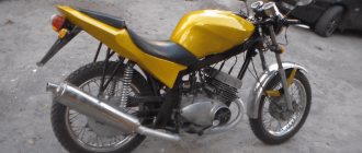
Motorcycle Features
The IZH Plante 5 motorcycle has the original name IZH 7.107. Just like the IZH 6, it belongs to the middle class of motor vehicles, designed for movement on roads with any surface. The main feature is the use of an oil pump; when refueling there is no need to add oil to the tank, as well as a contactless ignition system that operates independently of the battery.
It became possible to start a motorcycle from a pusher. To do this, you need to turn on the ignition, second gear and, when pushing the bike forward, the engine starts. True, without a battery, operation is possible only during daylight hours.
The Fifth Planet can be equipped with a cargo trailer and a passenger stroller. To reduce the clutch release effort, the bike has a clutch consisting of 7 pairs of discs. Vibration dampers are installed on the cylinder ribs. An important feature of this series is the presence of hydropneumatic suspension with disc brakes, which contributed to a smooth ride. The power is 22 horsepower, the maximum possible speed is 120 km/h. The volume of the two-stroke single-cylinder engine is 346 cm3. The power unit has good traction at low speeds.