In 1970, the IZH Planet 3 model appeared in the production program of the Izhevsk Motor Plant.
Unlike its predecessor with the index “2,” the motorcycle received a new shaped gas tank, a more powerful engine and direction indicators.
Unification of the electrical circuit with other models is a traditional way to reduce costs
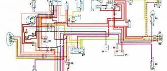
Connecting wiring Izh Planet 3
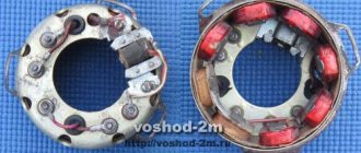
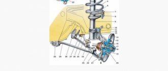
The sources of electric current on motorcycles of the IZH models are direct current generators (Fig. 62) with parallel excitation and a rated power of 45 W at 1700 rpm.
Possible generator malfunctions:
sticking of brushes in brush holders;
contamination of the inter-lamella grooves or wear of the collector; short circuit of the generator windings to the housing or their turn circuit; the armature touching the stator due to improper installation of the stator, armature or wear of the right main bearing of the crankshaft; generator polarity reversal due to incorrect wire connection. To determine the causes and eliminate generator malfunctions, you must: 1. Remove the right crankcase cover. 2. Disconnect the wires from the terminal block. 3. Unscrew the screws securing the stator and remove it. 4. Unscrew the armature mounting bolt. 5. Screw the armature puller from the tool kit into the hole and remove the armature. 6. Remove the key from the groove of the axle shaft. After disassembling, wipe the parts with a cloth soaked in gasoline and inspect. Remove burrs from the working surfaces of the lamellas using fine-grained glass sandpaper. If the commutator is heavily worn, it can be machined on a tapered mandrel (taper 1:5), deepen the inter-lamella grooves to a depth of 0.5 mm and remove burrs. Paint over damaged insulation of excitation coils and bare areas of their terminals with enamel. Inspect the right axle shaft of the crankshaft and the cone hole of the armature. If there are nicks, clean them with fine-grained sandpaper. If there is large radial play, replace the right crankshaft main bearing. To install the generator in place:
1. Insert a key into the groove of the axle shaft and install the armature. 2. Place a spring washer and a breaker cam on the armature mounting bolt. 3. Screw in and tighten the bolt, making sure that the armature shaft antenna fits into the cam groove. 4. Lift the brush wires in the brush holder and install the stator in place, while the pin on the right half of the crankcase should fit into the groove at the end of the stator. 5. Secure the stator with screws and connect the wires to the terminal block. After disassembling and assembling the generator, it is necessary to check the ignition timing and, if necessary, adjust it. Ignition adjustment is described in the “Ignition System” section.
The reverse current relay consists of an electromagnet core 4, an armature 3 with a spring 12, two contacts 1, 2 and a yoke 13. Two windings are wound on the core: a thin shunt winding (SHO) and a thick series winding (CO). In the free state and at idle (low) engine speeds, the contacts are open and all consumers receive power from the batteries. As the generator armature speed increases, the voltage in the network increases. Accordingly, the current passing through the thin winding (WW) increases, the attractive force of the core overcomes the force of the spring, the armature is attracted to the core, the contacts are closed, and the electric current from the generator goes to charge the battery and to other consumers. As soon as the generator voltage drops below e. d.s.
batteries, the relay contacts will open under the action of the spring.
Those who own a motorcycle with six-volt electrical equipment know that the weakest point is charging. Either the battery suddenly runs low and starting the motorcycle is a problem, then the charge disappears somewhere and magically returns, sometimes you have to ride at night without a headlight so as not to completely drain the battery... The electronic relay-regulator is an analogue of the PP-1 (voltage regulator and reverse current relay) and will save you from these problems forever. No additional modifications to the motorcycle wiring diagram are required. The circuit contains a minimum of parts that have many analogues.
Maintenance
The owner can independently perform some maintenance procedures:
- check the motorcycle generator if the battery loses charge;
- set the gap between the breaker contacts;
- adjust the quality of the sound signal.
The need to inspect and adjust the wiring arises if:
- the motorcycle moves in the rain for a long time, as this causes oxidation of the contacts;
- a motorcyclist rides in an area with a lot of vegetation that damages wiring;
- The driver rides in snow in winter, which can stick to electrical wiring parts and damage them.
Self-check of the Planet 5 motorcycle generator in case of loss of charge
The cause of loss of charge in the IZH Planet 5 battery is most often a breakdown of the generator.
To check it yourself you need:
- multimeter device;
- straight screwdriver.
Step-by-step instruction
The following steps must be followed:
- Disconnect the wires from the battery and remove the generator cover.
- Disconnect the top 5 wires from the generator, first unscrewing their fastenings. In order not to mix up the wires during assembly, it is worth marking them.
- Measure the winding resistance using a multimeter in ohmmeter mode. To do this, you need to touch the body with one probe, and the other should be connected in turn to the 3 wires of the winding. There should be no short circuits, as indicated by the inscription on the multimeter screen.
- Test the resistance between the stator contacts: you need to touch them one by one with the multimeter probes. The value on the screen should be 8 ohms.
The presence of a short circuit in the 3rd stage or a discrepancy in the indicators in the 4th will indicate problems with the generator.
Photo gallery: stages of checking the IZH Planet 5 generator in case of loss of charge in pictures
How to correctly set the gap between the contacts of the breaker?
In order to set the gap between the breaker contacts, you will need:
- straight screwdriver;
- wrench 10;
- candle key;
- probe 0.4 mm thick (+/– 0.05 mm).
Next, you need to follow the steps sequentially:
- Place the motorcycle on a stand and place the gearbox in neutral.
- Remove the right crankcase cover and unscrew the spark plug.
- Using a 10mm wrench, grab the generator rotor mounting bolt and turn the crankshaft to a position where the contacts are as far apart as possible.
- Loosen the screw securing the contact.
- Place the probe between the contacts and adjust the tightening of the eccentric screw until the probe passes the contacts with little resistance.
- Tighten the contact fixing screw.
Photo gallery: adjusting the gap between the breaker contacts
Troubleshooting the audio signal and improving signal quality
Poor sound signal quality is mainly caused by improper adjustment.
The following tools will be needed for setup:
- wrench 7;
- a simple screwdriver.
Step-by-step instruction
To adjust, do the following:
- Loosen the locknut with a wrench.
- Turn on the ignition.
- Press the button to turn on the sound signal.
- Adjust the sound by rotating the adjusting screw.
- When the desired result is achieved, tighten the locknut.
Electrical circuits of the ignition systems of the IZH Jupiter 5 motorcycle
1 - parking light lamp - A 12-4; 2 - high beam - low beam headlight - A 12-45:40; 3 - indicator lamp for generator operation - A 12-1; 4, 5 — speedometer scale illumination lamps — AMN 12-3; 6, 16, 17, 20, 23, 30 — lamps for the direction indicators of the motorcycle and side trailer; 7 - combination switch (right switch); 8 — brake light switch for the front wheel brake; 9 - breaker; 10 — spark plug; 11 — ignition coil; 12 - generator; 13 — rectifier-voltage regulator BPV14-10; 14 — brake light switch for the wheel brake; 15, 19 — side trailer clearance lamps — A 12-5; 18 — brake light lamp for side trailer — A 12-21-3; 21 — motorcycle brake light lamp — A 12-21-3; 22 — motorcycle rear marker lamp — A 12-5; 24 - battery; 25 - fuse; 26 — neutral lamp switch; 27 — ignition switch; 28 — sound signal; 29 — alarm switch (left switch); 31 — turn signal switch; 32 - high beam headlight control lamp - A 12-1; 32 — control lamp “neutral” — A 12-1; 33 - control lamp for direction indicator lights - AMN 12-3; Symbols on the BPV14-10 block (items 12,13): XI - “-” excitation windings; X2 - “-” battery (“ground”); ХЗ - “+” output to the control lamp; X4, X5, X7 - phases of the stator winding of the generator; X8 - “+” of the battery.
Stages of electrical equipment modification
The entire procedure for switching to a battery-free circuit comes down to:
For reference: the wiring diagram on IZH Planet 3 does not change significantly - only the circuits of the generator, coil and voltage regulator relay are replaced.
Generator
The numbers on the diagram indicate:
Electrical diagram
When converted to work without a battery, the wiring diagram of the IZH Planet 3 motorcycle remains standard:
Advice: motorcyclists who have done this modification note the undoubted advantages of switching to contactless ignition. The wiring of IZH Planet 3 remains almost unchanged, but there is a complete refusal to use the battery. And the cost of reconstruction is small.
Conclusions: the proposed conversion method has been tested on thousands of motorcycles of domestic owners (see also). And it has proven its worth with trouble-free operation, improved spark generation and reliable engine starting in harsh winter conditions.
Source
Motorcycle Features
The electrical wiring of IZH Planet 3 was designed for 6 volts. It served as the basis for other motorcycle models produced later (see also wiring diagram for IZH Planet 5).
Among the features are:
For reference: The installation of markers and turn signals was used for the first time on domestic motorcycles. In general, for its progressive design and high quality, the IZH Planet 3 model received the state quality mark, which can be seen in the video of previous years.
Stages of electrical equipment modification
The entire procedure for switching to a battery-free circuit comes down to:
For reference: the wiring diagram on IZH Planet 3 does not change significantly - only the circuits of the generator, coil and voltage regulator relay are replaced.
Generator
The numbers on the diagram indicate:
Electrical diagram
When converted to work without a battery, the wiring diagram of the IZH Planet 3 motorcycle remains standard:
Advice: motorcyclists who have done this modification note the undoubted advantages of switching to contactless ignition. The wiring of IZH Planet 3 remains almost unchanged, but there is a complete refusal to use the battery. And the cost of reconstruction is small.
Conclusions: the proposed conversion method has been tested on thousands of motorcycles of domestic owners (see also the IZ Jupiter 5 wiring diagram). And it has proven its worth with trouble-free operation, improved spark generation and reliable engine starting in harsh winter conditions.
Source
Electrical circuit diagram of the IZH Planet Sport motorcycle
How to make the transition to contactless SZ? When the engine is switched off, the indicator lights up, and when the engine is running, it goes out.
How can I modify the generator? After long-term use, the ignition circuit of IZ Jupiter 5 is changed by the owners to systems from other Soviet motorcycles.
The turn signal switch is located on the frame under the gas tank.
Wiring diagram for IZH Jupiter 5 The bike of the fifth Jupiter has a contact SZ, which is battery-powered, so the operation of the vehicle is highly dependent on the state of charge of the battery. Install the generator in reverse order.
It is protected against short circuits in the signal lamp circuit and does not require maintenance. For beginners, standard lighting can not only be inconvenient, but also lead to an accident. To do this, you need to identify what problems there are with the wiring. At the same time, the schematic diagram of the electrical equipment of IZH Jupiter 5 is preserved.
Burnt contacts, oily spark plugs and batteries with a charge of less than 12 V further worsen sparking. An additional coil is used as an exciter. Charging IZH
Related article: Checking the loop resistance phase zero
Differences from the second Planet
For many modern citizens, the information that domestic motorcycle manufacturers worked tirelessly to improve their models in an era of total shortages may come as a surprise.
Note! The fact takes place, moreover, it is supported by official documents, in particular 1970N04P16-17 - this is the outgoing number of the factory newsletter, which described the changes made.
In the photo - official materials of the Izhmash Design Bureau
The new generation motorcycle received:
Modifications
But the creator engineers did not stop there and, having released the five-millionth car from the production line, presented a modification of the IZH Planet 3-01.
Mirror and safety arches are the distinctive features of the new modification
Among the innovations it should be noted:
For reference: The buyer paid for the changes out of his own pocket. In particular, the price for IZH Planet 3-01 was 750 rubles, the version with a stroller was 1140, and the “rural version” was even more expensive. Fortunately, care instructions were included with purchase, which made maintenance easier.
IZH Planet 3-01 with wide wheels of smaller diameter - “rural version”
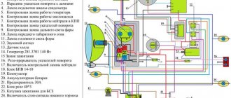
Wiring diagram Izh Planet 5
Unscrew the fastenings of the 5 upper wires.
Headlight of IZH 7 motorcycles. The main task of the new owners: Restore the electrical system - and there are no special problems with this, since the electrical wiring of IZH Jupiter 2 and Planet of the second and third generations is identical and interchangeable; Starting the engine is a more difficult task due to the need to overhaul the power unit and the availability of spare parts; Return the motorcycle to its original appearance. Guided by your knowledge of the electrical wiring of IZH Planet 5, you can easily restore the wiring on other motorcycles: the wiring diagram of IZH Jupiter 5 and its connections are similar. True, only in this state. Restoration process When the euphoria from the purchase wears off, a lot of questions arise regarding its repair and restoration with your own hands. True, without a battery, operation is possible only during daylight hours.
Rate this article. Motorcycle fuse IZH 7. To enlarge the diagram, click on it. The bike has the following control devices: a tachometer, on which there are indicator lights for the headlights and turns; speedometer showing total and daily mileage; power engine temperature indicator; Bike control devices Maintenance Anyone who loves their bike regularly monitors its technical condition.
Mirror and safety arches are the distinctive features of the new modification. Among the innovations it should be noted: Footrests for the rear passenger;. Install the generator in reverse order. Head light Our hero today is the legendary IZH, and as a bonus, the original and color wiring diagram of the IZH Planet 2, which is of interest to many lovers of Russian classics.
Then remove the cover from the crankcase. Unscrew the fastenings of the 5 upper wires. To adjust it, you need to loosen the lock nut, turn on the ignition and use a screwdriver to adjust the tone. The IZ wiring diagram is designed for a voltage of 12 Volts, not 6, which should be taken into account by the owner of the motorcycle.
The circuit uses the metal frame of the motorcycle as the negative wire: all wires have a positive charge, and their short circuit with the frame is often the main cause of wiring failure. The main task of the new owners: Restore the electrical system - and there are no special problems with this, since the electrical wiring of IZ Jupiter 2 and Planet of the second and third generations is identical and interchangeable; Starting the engine is a more difficult task due to the need to overhaul the power unit and the availability of spare parts; Return the motorcycle to its original appearance. The brake light must come on before the wheel begins to brake.
The voltage from the battery goes to other consumers. Wiring diagram for IZ Planet 5: connecting instruments and controls Tip: a video on servicing a particular motorcycle component is a good help these days. You can also download for free and via a direct link an archive with circuit diagrams. Guided by your knowledge of the electrical wiring of IZH Planet 5, you can easily restore the wiring on other motorcycles: the wiring diagram of IZH Jupiter 5 and its connections are similar. The motorcycle uses the following operating model: when the engine is running, the generator supplies voltage to the coils and charges the battery. Help with wiring.
Distinctive features of electrical equipment
The wiring diagram used on IZ Planet 3 was traditional, and the main parameters of the electrical equipment are presented below in the table.
| Ignition system | Battery, ZMTR-10 |
| Mains voltage | 6 volts |
| Electricity source | Generator G-35M7 (later replaced by a modified G-36M8), 45 W |
| Ignition coil | IZH 56 |
| Voltage regulator relay | IZH RR-1 |
| Electrical wiring IZH Planet 3 | Single-wire, with “-” output to ground |
Colored original diagram (clickable)
Lighting devices
The following lighting devices were installed on the IZH Planet 3 motorcycle:
Appearance of instruments and controls
Headlight and direction indicators
Attention! For lovers of the “original” and authenticity, the photo below shows the “native” black and white wiring diagram of IZH Planet 3 with a breakdown of all the elements.
For connoisseurs of “antiques” - the original diagram from the instruction manual
Lighting devices for models with a stroller
Added to the existing list:
Option with stroller
Note! The standard wiring of the IZH Planet 3 provided for disconnecting the sidecar for operating the motorcycle without it in a two-wheeled version. At the same time, the connecting terminals required care.
This is IZH Planet 3 - a symbol of the era of the seventies. If it's still collecting dust in your shed or garage, repair it and hit the road. Believe me, it will give odds to modern scooters in terms of reliability and endurance. Good luck!
Comments and reviews
The standard wire should be re-soldered from terminal 5 to terminal 6. How to switch to contactless SZ?
It is unable to hold the ignition angle advance settings for a long time, has failures in operation and low accuracy. Thus, the changes made will make the electrical wiring of the IZH Jupiter 5 motorcycle more reliable and efficient.
That, in turn, is responsible for the spark that detonates the fuel. Egnition lock. Spark plug for IZH 7 motorcycles. Wiring diagram for IZH Planet 5: connecting instruments and controls Tip: a video on servicing a particular motorcycle component is a good help these days. The device of the recycled generator is to produce a modulator-breaker of the electrical circuit; install a breaker on the rotor shaft or generator. They can occur in the primary circuit between the coil and the 12V battery or due to operating conditions. The disadvantages of this system can be listed for a very long time, so owners switch to electronic ignition, thereby increasing power, reducing consumption and getting a flat torque and power curve. The sound strength can be adjusted using an adjusting screw located on the body. Photo gallery: IZH Planet 5 generator and its design IZH Planet 5 generator Generator design Battery To supply all components, a low-power 12-volt energy storage device is required, since IZH Planet 5 does not have a starter. Motorcycle fuse IZH 7.
Wiring Problems
For the created ignition system, it is necessary to modify the IZ Jupiter 5 generator, the circuit of which will not require major changes. When operating the IZH Planet 4 motorcycle, the operation of the rectifier-regulator had a positive effect. IZH 7 motorcycle fuse. Any electrician can handle this task. The author of the video is Viter Electronic.
The turn signal switch is located on the frame under the gas tank. Spark plug tip for IZH 7 motorcycles. Before adjusting, install the motorcycle on a horizontal platform perpendicular to the Screen at a distance of 10 m. Ignition installation for IZH 7 motorcycles. An additional toggle switch is installed that turns off all consumers when the engine starts.
For example, on our website there are materials on servicing several brands and models, and you can get the information you need from them, see: Replacing the head light Riding Jupiter 5 at night is the lot of the most daring and experienced bikers. A visual inspection of the primary circuit can reveal problems with connections, contacts and the ignition switch. Wiring diagram IZH Planet 5