Photo report: Replacing the connecting rod bushing “Izh-Planet”, “Ant”
I don’t understand these designers who put plain bearings in the upper head of the connecting rod (meaning 2T engines in which it is impossible to lubricate the upper head of the connecting rod under pressure). For what? This engine unit already gets the full brunt of high temperatures, lack of lubrication, and significant loads; under such conditions, the rolling bearing quickly fails. There is a long-proven solution that consists in installing a rolling bearing (cage), but no... So the “lucky” owners of “sovietcycles” have to take the rap for the technical mistakes of the manufacturer.
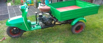
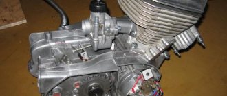
I think there is no point in showing in detail how the bushing is changed on all models of motorcycles, so I will show you the whole process on the crankshaft from the Ant scooter.
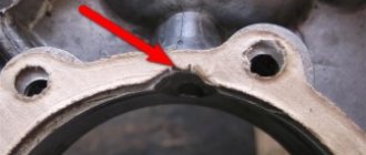
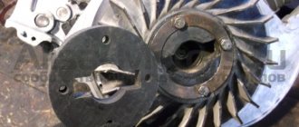
So, as we see, the bushing of this connecting rod was harshly “knocked off”, so whether you like it or not, you will have to change it.
The working surface, to put it mildly, is far from ideal.
To press out the old bushing we will need: a long pin or bolt with a nut, several washers, any bushing or piece of tube whose outer diameter is slightly smaller than the inner diameter of the connecting rod head, another bushing whose inner diameter is slightly larger than the outer diameter of the bushing itself.
The 12 head, which easily passes through the connecting rod, worked well for me as a bushing for pressing out. We pass the bolt through the head, then through the connecting rod, on the other side we put another bushing, put on the washer and screw on the nut. I came up with something like this design.
Tighten the nut.
As you can see, the process has begun.
A couple of minutes of work and voila, the bushing is removed.
Now the hardest part is installation. The most difficult part of installation is ensuring maximum tension in the mating of the two bushings. You must try to make the tension as large as possible, otherwise the bushing may turn in the connecting rod head and then all is lost.
To ensure the necessary tension, the joint of the bushing must be filed, then try to install it, see how the bushing “behaves”; if you cut a lot, the bushing will fit into the head very easily, which is not acceptable. If you cut a little, the bushing will be deformed when pressed.
I won’t tell you the exact numbers when filing a joint, I do everything by eye, sometimes the required tension can be achieved only the second or third time, so I buy several bushings at once so as not to have to go to the store again. Sometimes I came across bushings on sale that there was no need to saw off - they fit into the connecting rod with a very good fit, but this is rare, usually you have to saw off.
I file the joint with a regular hacksaw. I had to cut twice, first one pass, then I lightly pressed the sleeve with pliers so that the joints would meet and sawed again.
After filing the joint, using exactly the same principle, using a bolt and washers, we press the bushing into place; when pressing the bushing, try to position the joint towards the lower head of the connecting rod.
The bushing turned out to be slightly wider than the connecting rod, so during pressing it rested against the washer. To press it a little on the other side, I put the bushing in and pressed it a little so that it came out equally on both sides.
We use needle files to saw through the window for lubrication.
We take a sliding reamer and slowly begin to calibrate the hole little by little until the piston pin, lubricated with engine oil, moves into place with the force of a finger.
Replacing the connecting rod bushing IZH Planet 5
The cylinder-piston group can be disassembled without removing the engine from the motorcycle. This, as a rule, has to be done to clean the piston and combustion chamber from carbon deposits, as well as to replace worn parts.
1. Remove the fuel tank.
2. Unscrew the exhaust pipe nuts and move the pipes away from the cylinder.
3. Remove the carburetor.
4. Remove the tip of the high voltage wire from the spark plug, remove the ignition coil, and unscrew the spark plug.
5. Disconnect the decompressor cable and unscrew the valve.
14 mm socket wrench
Unscrew the six nuts securing the cylinder head in a criss-cross pattern.
7. Remove the head.
14 mm spanner
unscrew the four nuts securing the cylinder to the crankcase.
9. Remove the nuts with spring washers.
10. Lower the piston to bottom dead center by rotating the motorcycle wheel or pressing directly on the piston. Remove the cylinder.
11. Cover the opening of the crank chamber with a clean rag to prevent foreign objects from getting into it.
12. Turn the cylinder over, install it on the studs and, carefully prying it with a knife, remove the gasket from the cylinder.
13. Similarly, remove the carburetor gasket (if it was not removed along with the carburetor).
14. Inspect the cylinder mirror. No scuffs, signs of heavy wear, grooves, enveloping of aluminum from the piston and other damage are allowed on it. This cylinder must be repaired or replaced.
You cannot grind the cylinder mirror with sandpaper and then polish it. The only possible processing is boring on a lathe to the repair size with mandatory subsequent honing. In this case, it is necessary to install a piston and rings of repair sizes (see below).
15. Using a scraper or knife, clean the cylinder exhaust windows from carbon deposits. Before this, carbon deposits can be softened with kerosene or acetone.
16. Check the condition of the threads in the spark plug hole. If the thread is damaged by more than a third in height, replace the cylinder head.
17. Similarly, inspect the thread of the hole for the decompressor.
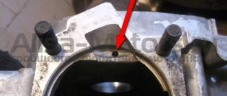
If necessary, the cylinder head can be repaired by installing a liner in it. To do this, drill the spark plug hole to a diameter of 18.4 mm and cut an M20x1.5 thread in it. We grind a futor from brass or bronze (see figure) and, wrapping it into the hole, counter flare the lower edge. Such footwear is also available for sale.
Spark plug hole
18. Inspect the sealing band of the cylinder head. If unevenness is noticeable on the belt, grind the belt on a bench plate (with paste for grinding valves) or with an even, small abrasive stone.
19. Using fine sandpaper, clean the surface of the combustion chamber from carbon deposits.
20. It is useful to polish the combustion chamber with the finest sandpaper (with water), and then with GOI paste to a mirror shine. This way there will be less carbon deposits on it.
21. If the piston rings are to be replaced, they can be removed by breaking them. Otherwise, carefully place strips cut from a plastic bottle under the rings and remove the rings from the piston.
When using the old rings later, we mark them so that they can be installed in their original places during reassembly.
22. Using snap ring pliers or round nose pliers, squeeze and remove the piston pin snap rings from the piston. Do not compress the rings excessively to avoid permanent deformation.
23. Using a hammer, knock out the piston pin through a suitable mandrel (it’s easier to do this with two people).
24. Remove the piston.
25. We clean the piston bottom and ring grooves from carbon deposits (you can use a piece of an old ring). It is recommended to first soak the piston in acetone. It is also recommended to sand with fine sandpaper (with water) and polish the piston bottom (including a new one) with GOI paste, so less carbon deposits will be deposited on it.