The first production Voskhod motorcycle was equipped with a K-36B type carburetor, which had two metering systems - main and idle, as well as an enrichment device.
To rinse and clean it is necessary to disassemble in the following order: 1 - close the gasoline tap and disconnect the gasoline hose; 2 — unfasten the latches and remove the housing cover along with the cables, spool and fuel corrector; 3 - remove the rubber coupling; 4 — unscrew the two fastening nuts and remove the carburetor; 5 — remove the sealing gaskets; 6 - perform a complete disassembly.
Wash the removed parts with clean gasoline, inspect and reassemble in the reverse order. The factory settings ensure maximum and optimal engine efficiency.
Return to content
Adjusting the K-36B carburetor
Adjustment at idle speed is carried out as follows: 1 - before starting the adjustment, you need to start and warm up the engine. 2 — set the fuel corrector coin to the farthest position from you; 3 — by turning out or screwing in screw 14, set the minimum possible engine speed; 4 - tighten screw 13 until it stops, gradually unscrew it, achieve clear, stable operation of the engine; 5 - set screw 14, lower or raise the throttle to the minimum stable idle speed.
The quality of the mixture is adjusted in operating modes by moving the metering needle 6 in the throttle valve to one of the five annular grooves, while raising the metering needle ensures enrichment of the working mixture, lowering ensures depletion.
Return to content
Jawa 250/350
On YAVA-250 motorcycles with indexes 559/02 and 559/04, Ikov 2926SD (before 1967) and 2926SBD (after 1967) carburetors were installed. On YAVA-350 motorcycles models 354/06, 360/00, Ikov 2926SBD carburetors were used.
The first carburetor has a separate starting carburetor (enricher), which is activated by lifting the cable using a lever on the steering wheel. Its presence on the 250 cc motorcycle model is due to the fact that a smaller single-cylinder engine is more difficult to start in cold weather than a two-cylinder one. Otherwise, these two carburetors are almost identical. Later, rotary air dampers were installed on both motorcycles on the carburetor inlet pipe. A separate starting enrichment unit was no longer needed.
- How to Correctly Adjust the Carburetor Gas 53
Before you begin adjusting these carburetors, you must perform the following procedure:
- Open the gas tank tap and wait until the carburetor float chamber fills. Close it and remove the chamber cover to make sure there is no dirt on the bottom. In case of contamination, remove the carburetor and blow out all channels with compressed air or rinse in kerosene. Attention, to prevent contamination of the carburetor channels, it is necessary to install a fuel filter in the gasoline fuel supply line. Its material should consist of a thin mesh, which will allow the incoming gasoline to be cleaned of oil and foreign impurities.
- Be sure to check it out. Is the ignition timing set correctly?
- Check the condition of the filter element in the air filter. If the paper filter is dirty, it needs to be replaced. It is enough to wash the filter oil element in gasoline and moisten it with a small amount of engine oil.
- Setting the screws according to the table. Set the quality adjusting screw (18) and the throttle needle (25) to the positions indicated in Table 2. Adjust the free play of the throttle cable sheath to 2-3 mm using the stop (1).
- Setting the minimum speed. Start the engine, use the quantity screw (12) to set the minimum stable engine speed. Ride a motorcycle for 5-10 km, warming up the engine.
Drawing of carburetor detail Ikov 2926SD
The table shows the adjustment data of the 2926SBD carburetor
The process of adjusting the carburetor itself proceeds in a strict, sequential order:
- Installing the “correct” spark plugs. For driving in warm weather and after the break-in period, install analogues of “cold” Pal -8.9 spark plugs (NGK BP8HS-BP7HS, Brisk N14-15, Bosch W3AC-W4AC, etc.).
- We are looking for minimum speed. Start the engine and use the speed screw (12) to find the minimum engine speed at which the motorcycle does not stall.
- We increase the speed. Turn the quality screw (18) slowly to the left to increase the speed.
- Again, use the quantity screw to “feel for the minimum.” Repeat the operation until the motorcycle begins to stall at idle. When the limit is found, the quality screw needs to be tightened a little, enriching the mixture. Depress the clutch and engage gear. In this case, the motorcycle should work steadily and not stall (of course, with a working clutch). If the motorcycle stalls, you can raise the throttle a little. Attention, to adjust the carburetor in medium load mode, you should find a straight road with horizontal surface, without obstacles. This is necessary to control the adjustment when the motorcycle is moving in direct gear at a speed of 40 km/h and above. The weather should preferably be warm and calm.
- Check the operation of the engine while the motorcycle is constantly moving at a speed of 60-70 km/h. If the engine operates unstably (every cycle), then these are all signs of “flooding” the spark plug due to a rich mixture. In this case, the needle must be lowered until the motorcycle begins to operate normally.
- Check the acceleration of the motorcycle over a 1 km section. Accelerate the motorcycle from 40 to 80 km/h and evaluate the engine performance. The sound should be clear, without interruptions, acceleration should be smooth, with a uniform increase in engine speed.
- Assess engine response. Let's see how the motorcycle reacts when you sharply turn the gas lever, when accelerating over a short distance. Overclocking must be efficient. The main condition is the absence of a “failure” - the effect of a sharp leaning of the mixture due to the rapid opening of the damper. This can happen if, when moving the needle, it was lowered very low or due to air leaks in the intake tract. In the second case, the reason lies in incorrect idle speed adjustment.
Useful video
Visual video material on removing, cleaning, tuning and adjusting the Java 350 model 354 carburetor.
Sometimes, while operating a motorcycle, conditions may arise when it is necessary to change the current carburetor adjustment (weather conditions, number of passengers and motorcycle load, use of fuel with a different octane number). In this case, it is enough to replace the main fuel jet, which can be accessed by unscrewing the plug at the bottom of the carburetor.
For example, if the motorcycle is operated in winter weather, then it is necessary to install a larger fuel jet (main fuel jet). You can select it experimentally by determining the composition of the mixture by the color of the central electrode of the spark plug.
When mixed optimally, the color should be brown, reminiscent of rust or a shade of red brick. Accordingly, if the mixture is too rich, the insulator will be covered with black soot. And with a lean mixture, the electrode will be light yellow or gray. It is the last option that poses the greatest danger. In this case, the electrode may melt, and its parts will fall into the CPG, which will lead to expensive repairs.
Attention! The condition of the spark plugs should be assessed after a short motorcycle ride at a speed of 75-80 km/h (1-2 km). The spark plug must be unscrewed from the cylinder immediately after stopping the motorcycle, and it must be turned off while moving. Only if these conditions are met will the color of the spark plug electrode be closest to the actual one.
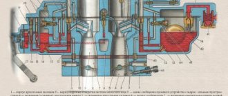
K-36B carburetor diagram
1. Fitting. 2. Fuel corrector. 3.Fuel corrector spring. 4. Locking needle. 5. Throttle valve spring. 6. Dosing needle. 7. Mixing chamber housing. 8. Air intake channel. 9. Sprayer. 10. Main jet. 11. Fuel corrector jet. 12. Float. 13. Idle speed adjustment screw. 14. Throttle set screw. 15. Throttle valve. 16. Cover of the mixing chamber housing. 17. Cable guide. 18. Leaf spring. 19. Float release button. 20. Float chamber cover. 21. Float chamber housing.
Return to content
It is the base model of standardized carburetors developed by Lenkarz, for engines with a displacement from 125 to 350 cm3. Carburetor modifications are supposed to be installed on the following engines: K-36B - on the engine of the VP-175 Vyatka scooter; K-36V - for the engine of the M-600A motor pump; K-36G - for the T-250 scooter engine; K-36E - for the engine of the SZA-M motorized stroller; K-36ZH - for the engine of the IZH-Jupiter motorcycle; K-36I - for the engine of the IZH-Planeta-2 motorcycle; K-36L - for boat engine SM-557L; K-36M - for the M-105 motorcycle engine and K-36P - for the MP-800A motor pump engine.
Carburetor modifications differ in the design of the fuel intake fittings in the float chamber cover and connecting pipes for mounting on the engine, as well as in the diameters of the diffusers and mixing chambers, the presence or absence of a fuel corrector and the adjustment of the metering elements.
Carburetor K-36, the general view of which is shown in Fig. 72, and the diagram in Fig. 73, single-chamber, horizontal, with an unbalanced float chamber and a flat U-shaped throttle valve.
The mixture composition is adjusted by mechanical braking of the fuel using a profiled needle and changing the vacuum behind the main jet.
The carburetor has a starting device, an idle system, a main system and a fuel corrector.
It consists of the following main parts cast from zinc alloy: the mixing chamber housing 21, made integral with the connecting flange, the float and nozzle chamber housing 8, which is a cast monoblock, and covers 1 and 6 of the mixing and float chambers. The housings are connected with three screws, and a cardboard spacer is installed between them. The mixing chamber cover 1 is attached to the housing 21 using two plate spring locks 10, and the float chamber cover b is attached to the housing 8 with two screws.
Housing 8 houses the float mechanism 7. The float is brass; in the center of it there is a fuel shut-off valve needle, which is fixed at the bottom with a spring lock.
The valve seat is made in a brass fuel supply fitting 4, which is poured into the cover in and represents c. she is one whole. Guides for the needle, made both in the lower part of the float chamber and in the fitting, ensure that the float moves only vertically. A starting device in the form of a float quencher 5 is also mounted in the lid of the float chamber.
The quencher is a rod with a spring. The spring tends to hold the rod in the upper position. To prevent it from falling out, dents are made in its lower part, which hold the rod in the chamber. Leaks in the socket of the drowner provide communication between the float chamber and the environment.
The main fuel jet 18 is screwed into the horizontal channel of the nozzle chamber.
The idle fuel nozzle 25, the fuel corrector nozzle 17 and the sprayer /5 are pressed into the vertical channels. All these channels are closed with screw plugs. The idle air jet 19 is also pressed into the inclined channel of the nozzle chamber.
A fuel corrector 3 is installed in the vertical channel of the nozzle chamber. The corrector consists of a rod and a needle. The needle at the top has a spherical surface and is hingedly connected to the rod. To allow fuel to exit the corrector system, an inclined hole is made in the nozzle chamber.
The profile of the main air path is designed to be conical, similar to a Venturi nozzle. In the front part of the mixing chamber housing there is a wide channel 14 for supplying air to the idle system.
In the slotted grooves between the inner walls of the mixing chamber and special recesses in the nozzle chamber there is a U-shaped throttle valve 13, made by stamping from sheet brass 1 mm thick.
There is a symmetrical cutout in the front of the spool.
The throttle valve 13, as well as the fuel corrector 3, is controlled by the driver using cables. To guide the movement of the cables in the carburetor, guide bushings 9 are screwed onto the mixing chamber cover.
Springs 11 and 2 are installed on the cables in the carburetor body, which tend to keep the throttle valve 13 and the fuel corrector 3 in the closed position at all times.
The metering needle 12 is secured in the throttle valve using a spring plate lock.
There are five grooves on the metering needle in its upper part, which allow you to change the carburetor adjustment during operation, and therefore the composition of the combustible mixture.
Two openings of the idle speed output channels are brought into the main air channel, one 23 behind the rear wall of the throttle valve and the other 22 in front of it. Through channel 20 and air jet 19, the idle system communicates with air channel 14.
When the engine is idling, throttle valve 13 is in the lower position.
Under the influence of vacuum, fuel from the float chamber through the fuel jets (main 18 and idling 25) flows to the output channels 22 and 23.
As fuel moves through the channels, it is mixed with air coming from channel 14 through air nozzle 19 and channel 20.
When the throttle valve 13 is in the lower position, i.e. at low idle speeds, air will also flow through channel 22, and the emulsion will exit only through channel 23. When the throttle valve is raised, fuel in the form of an emulsion will enter the main air channel through both output channel. The degree of closing of the throttle valve is determined by the position of the set screw 16 located in the housing 21.
When the throttle valve is in a closed position, there is a small gap between the lower edge of its rear wall and the wall of the nozzle chamber, i.e. above the outlet channels 22 and 23, through which air flows at high speed.
The fuel coming from the outlet channels is picked up by this air, atomized, partly evaporates and goes into the engine cylinder in the form of a combustible mixture.
Engine idle operation is regulated by adjusting screw 16 and idle speed adjusting screw 24, installed on the emulsion and located in the mixing chamber housing.
As the throttle valve opens (rises) the vacuum at the sprayer increases and the main dosing system comes into operation, and the share of the idle system operation decreases.
The location of the output channels, the dimensions of the idle fuel and air jets, as well as the depth of the throttle valve cutout and the height of the protruding part of the nozzle are selected such that they ensure a smooth increase in engine crankshaft speed when the throttle valve is opened until the main metering system is reliably included in the operation.
When the main metering system is operating, fuel from the float chamber through the main jet and then through the annular cavity between the walls of the atomizer and the metering needle enters the air flow passing through the main air channel. Here it is sprayed, partially evaporates and enters the engine cylinder in the form of a combustible mixture.
When the engine is running with the throttle valve partially open, the fuel flow through the main system is determined by the position of the needle in the nozzle, and consequently, by the opening of the throttle valve. When the throttle valve opens, the annular cavity between the needle and the walls of the nozzle increases and the role of the main jet as a metering element increases.
When the throttle valve is opened approximately 60-70%, the main metering element is the main jet. In this case, the idle air system will receive
air into the channel behind the main jet, slowing down the growth of vacuum.
If it is necessary to enrich the combustible mixture, a fuel corrector is used, which operates similarly to the main system.
When the needle is partially raised, the fuel consumption will be determined by the annular cavity between the needle and the channel walls. When the needle is raised, the metering element is the corrector jet 17. When the needle is fully raised, fuel consumption increases by 15-20%.
To ensure normal running-in of the motorcycle, a pin is installed on the cover of mixing chamber 1 on the inside, limiting the opening (lifting) of the throttle valve. After running in, the pin is removed.
The basic data of carburetors K-36, K-36ZH, K-36L and K-36I are as follows:
Adjusting the K-62V and K65P carburetor
Adjust the idle speed in the following sequence: 1 – screw screw 18 until it stops, which regulates the air supply for idle speed. Then unscrew one turn. 2 – Open the throttle slightly using the throttle. 3 – Start the engine and warm it up. 4 – Using bolt 16, lowering the throttle valve, achieve minimal stable engine operation. 5 – Unscrew screw 18 to set the maximum speed. 6 – Using bolt 16, lower the damper again to minimum speed. 7 – Check the adjustment. Sharply open the throttle with the throttle. If the engine stalls or there is a failure in operation. When switching from idle to main working. The adjustment is incorrect. Screw 18 needs to be used to enrich the fuel mixture - tighten it by a quarter. Or repeat the entire adjustment. 8 – Adjusted correctly, if there is no dip and the motor does not stall. And it continues to gain momentum.
Return to content
Basic rules for repairing a K65 carburetor
The K65 carburetor replaced the K62 carburetor.
Due to constant breakdowns and shortcomings, technologists decided to modernize it. Despite the fact that the K65 carburetor appeared quite recently, its adjustment is not difficult. There are some nuances that you need to know, but they can affect everyone. Even those who want to know how to adjust the carburetor on a scooter.
Before you begin your own repairs, you must fulfill some conditions.
- It is necessary to warm up the engine thoroughly;
- The carburetor must be in good condition. Otherwise, it must be blown out and cleaned;
- You should pay attention to the air filter. If necessary, it is washed.
Direct carburetor repair work begins with adjusting the free play of the throttle cable and the idle speed.
— The free play of the throttle cable is adjusted as follows: the lock nut on the bolt is loosened, the adjusting bolt is tightened and unscrewed until the free play of the cable is 1-2 mm.
This is interesting: Replacing the front engine mount of a VAZ 2114
— Adjusting the idle speed is done as follows: unscrew the bolt and thereby increase the speed. In order for the speed to be reduced, the bolt must be tightened. The idle speed will then be adjusted when the engine runs stably at minimum idle speed.
The K65 carburetor adjustment itself
This also includes adjustment of the main dosing system. For this purpose, several grooves are carved into the needle. By moving the latch along them, you can precisely adjust the fuel consumption. If the mixture needs to be enriched, the needle rises. If it is necessary to lean, the latch moves so that the needle drops.
Since the boundary at which the fuel is located in the float chamber greatly affects the quality of the mixture at all stages of engine operation, it also needs to be adjusted. To help the amateur car mechanic, there is a tongue on the float.
The fuel level will change if the tongue is bent or straightened. The best option for accurately adjusting the fuel level would be to measure using an ordinary ruler. It must be placed on the connector plane. The tongue should be bent so that the float strip is at the mark of 13 mm or plus/minus up to 1.5 mm.
To normalize the quality of the idle mixture, a special screw is provided that controls the volume of air entering the channel of the idle design. If you listen to the advice of specialists who have independently adjusted the idle system more than once, you need to perform the following steps:
- The screw is screwed in all the way and the idle speed is adjusted;
- You should check the motorcycle in action, that is, ride it;
- If acceleration, starting, and idling occur in normal mode, then it is worth unscrewing the bolt a little and checking how much worse or better these characteristics have become;
- If the parameters have become better, the bolt is unscrewed a little more, if worse, it is tightened;
- Similar procedures should be carried out several times.
This concludes the work on adjusting the carburetor of the K65 model.
Adjustment with dosing needle
The dosing needle for adjustment has five positions and is fixed with a special lock. Raise the needle one notch and increase the fuel supply. We lower it and reduce the fuel supply.
Under normal conditions, the needle is installed in the central groove.
When operating a motorcycle at high temperatures of plus 35 degrees and above, as well as in rarefied air at an altitude of 2000 and above above sea level. The needle should be released one division.
And vice versa at low temperatures of minus 15 degrees and below. The needle should be raised one notch
Return to content
Ignition and carburetor
It is these two components that, as a rule, determine the stability of the engine. Often, interruptions in the crankshaft rotation speed, loss of traction, and difficulties starting the engine are associated precisely with their malfunctions. Repairing the ignition and carburetor usually comes down to adjusting them. Setting the ignition includes setting the gap between the coil core and the sensor magnet within 0.295...0.305 mm. The piston ignition timing should be 3.5-5 mm to top dead center.
Adjusting the carburetor is somewhat more difficult. If you are repairing a Voskhod-3M motorcycle, then you will have to deal with the K65V carburetor, and the main tools will be the quality and quantity screws included in its design. Using the first, you can lean or enrich the mixture - change the proportion of fuel and air entering the cylinder. The second determines its volume per working cycle. With the standard setting, the quality screw is screwed in completely and then unscrewed half a turn. Then the rotation of the quantity screw achieves the minimum stable speed and the quality of the mixture is re-adjusted. Finding the optimal adjustment balance is a search for maximum traction and stability with minimum fuel consumption.
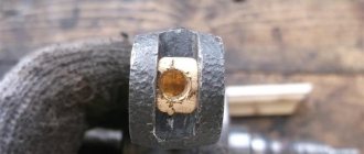
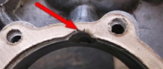
Adjusting the fuel level
For this purpose, there is a brass adjusting element on the float, as shown by the white arrow in the photo.
The entire adjustment process comes down to setting the float in a certain position. Remove the bottom carburetor cover and turn it upside down with the float.
We look from the side so that the mark on the float from the mold (black arrow shows) is parallel to the carburetor plane (red arrow shows).
In this position of the float, the fuel level will be within 12 ... 14 mm. This level is necessary for normal engine operation.
Return to content
Engine
The “heart” of a motorcycle, even with the most careful use, gradually wears out - this is facilitated by the abundance of heterogeneous mechanical loads in the cylinder-piston group and other moving parts, temperature effects on the metal, the chemical composition of the working mixture and exhaust gases.
DIY motorcycle repair Voskhod most often includes the following engine work:
- removing the power unit from the motorcycle frame;
- partial or complete disassembly of the internal combustion engine;
- replacing piston rings;
- restoration of the cylinder mirror;
- repair or replacement of the piston, connecting rod, crankshaft;
- replacement of support bearings, liners, seals;
- lubrication, fastening, adjustment work.
Engine repair, like the repair of other units, must be preceded by a comprehensive diagnosis of its technical condition, which includes an analysis of operational parameters (approximate indicators of developed power and speed, fuel consumption, sound of operation, color and character of the exhaust). If necessary, diagnostics are performed on the bench, and specialized instrumentation is used.
It is important to navigate the structure of a two-stroke internal combustion engine of a motorcycle and understand how each specific type of repair is performed. So, when replacing piston rings, you can do without removing the engine. It is enough to unscrew the stud nuts, remove the cylinder cover and, opening access to the piston, bring the piston to top dead center. Then the worn rings are removed and new ones are installed. The engine is assembled, not forgetting to replace the gasket. This completes the repair.
Much more complicated is the process of replacing the crankshaft bearings and its seals, the need for which, especially if the motorcycle is used incorrectly, arises quite often. You will need to disconnect and remove the internal combustion engine, clean its external surfaces, disassemble the crankcase, allowing access to the crankshaft, and dismantle the latter. It is important to be careful when knocking out old bearings - if they become distorted, they can damage the seat. And, no matter how trivial it may sound, do not forget to remove the retaining rings. Then the new bearings are carefully pressed in, the crankshaft is installed on the left side of the pan and the engine is turned over. A pin is put on the nuts and the assembled module is screwed into the studs. The power unit is assembled in the reverse order. In case of wear of the inner surface (mirror) of the cylinders, they are bored to repair size and ground. This is a complex and highly precise job that must be carried out by experienced professionals and using special equipment. However, preliminary work - removing and disassembling the internal combustion engine - can be done independently. After the repair, you will have to replace the piston with rings with parts from the corresponding repair group.
This is interesting: Design and adjustment of the OZONE VAZ 2107 carburetor
Scheme of the carburetor K-62V motorcycle Voskhod
1. Idle fuel jet. 2. Main fuel jet. 3. Float chamber. 4. Sprayer. 5. Float axis. 6. Float lever bushing. 7. Air channel. 8. Nozzles. 9. Dosing needle. 10. Body. 11. Throttle. 12. Needle lock. 13 Throttle spring. 14. Throttle lift limiter (removed after engine break-in). 15. Throttle control cable. 16. Throttle lift adjusting screw. 17. Cover. 18. Idle speed adjustment screw. 19. Fitting for fuel intake. 20. Transition hole. 21. Idle air channel. 22. Drainage hole. 23. Idle air channel. 24. Locking needle with washer. 25. Float. 26. Float sink.
Return to content
Carburetor of Izh Planet Sport motorcycle
Motorcycle Izh Planet Sport 350. A legend of the Soviet motorcycle industry. Early models of the motorcycle were equipped with Japanese components, in particular a Mikuni carburetor with a diffuser diameter of 32 mm. Thanks to him, the motorcycle's power was 32 hp. at 6700 rpm.
The reliability of the carburetor is explained by the simplicity of the design. The throttle has a cylindrical shape. To drain excess fuel, there is a special plug at the bottom of the float chamber. The carburetor is adjusted using an air screw and an idle screw (similar to the K-68). To make starting the engine easier in cold weather, there is an enrichment lever.
Later versions of the motorcycle began to be equipped with the domestic K-62M carburetor. The engine power with it dropped to 28 hp.
As you can see, different carburetors were installed on Izh motorcycles of the Planet line, but mostly domestic ones. As engine power increased, the characteristics of carburetors also changed. For high-quality and long-term engine operation, it is necessary to inspect and clean the carburetor in a timely manner (every 3000-4000 km). If desired, imported carburetors can be installed on Izh Planet motorcycles. The main thing is to choose the right jets with the required throughput and match the diameter of the diffuser.