Carburetor engine fuel system
(Fuel injection system)
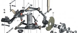
| 1 – fine fuel filter; 2 – fuel pump; 3 – transverse rod of the carburetor control drive; 4 – carburetor; 5 – corrugated hose for intake of heated air from the exhaust manifold area; 6 – cold air intake pipe; 7 – thermostat; 8 – air filter housing; 9 – crankcase gas exhaust pipe; 10 – air damper drive cable; 11 – air damper control handle; 12 – plug; | 13 – hose of the fuel tank and filler neck; 14 – separator and hatch hose; 15 – separator hoses; 16 – separator; 17 – fuel receiver with fuel level sensor; 18 – fuel tank; 19 – throttle valve control pedal; 20 – fuel supply line; 21 – fuel drain line; 22 – check valve; 23 – longitudinal thrust. |
Diagram of a power system with two fuel tanks (Niva with a long wheelbase)
The fuel supply is located in a tank located under the rear seat and covered with a metal casing. The tank is stamped from leaded steel sheet, its upper and lower halves are welded together. The filler neck is connected to the tank by two hoses; The lower (thick) hose is used to fill fuel, the upper (thin) hose is used to remove displaced air during refueling.
The hoses are fixed with clamps. The tank plug is sealed. On each side in the upper part of the tank, fittings extend from it, onto which thin plastic tubes for ventilation of the tank are placed. They are connected to a separator, which, in turn, communicates with the atmosphere through a tube exiting near the filler neck. On vehicles with a toxicity reduction system, the separator is connected by hoses and pipelines to the adsorber in the engine compartment. The design and operation of this system are described in the section Fuel system (injection).
A fuel receiver with a fuel level sensor is attached to the top of the fuel tank on six studs through a rubber gasket. Fuel is drawn from the tank under the influence of vacuum created by the fuel pump. To pre-clean the fuel, use a mesh filter at the end of the fuel receiving tube of the tank.
From the tank, fuel flows through a rubber hose into a pipeline leading into the engine compartment, and then through a rubber hose to the fine filter. Filter – with a paper filter element, non-separable design. There is an arrow on its body, which must coincide with the direction of fuel movement (forward).
After the filter, the fuel enters the fuel pump and then into the carburetor (these units are also connected to each other by rubber hoses). Excess fuel from the carburetor (the pump is designed to supply excess fuel) is drained through hoses, a fuel line and the drain pipe of the fuel receiver with a fuel level sensor back into the tank. Fuel circulation prevents the formation of vapor locks in the power system. A check valve is installed in the section of the drain hose in the engine compartment, allowing fuel to flow in only one direction. All hoses of the power system are fixed to the fittings and tubes with clamps.
The fuel pump is a diaphragm type, mechanically driven from the eccentric pusher of the oil pump drive shaft and the ignition distributor, with a manual pumping lever. The pump consists of a lower housing with drive levers, an upper housing with valves and fittings, a diaphragm assembly and a cover. The diaphragm assembly is installed between the upper and lower housings.
Two diaphragms are installed on top (working ones), and one (safety) on the bottom: it prevents gasoline from entering the engine crankcase if the working diaphragms rupture. In this case, leaked gasoline is discharged through holes in the external spacer located between the safety and working diaphragms.
The diaphragms, together with the internal spacer and plates (from the outside), are assembled on the rod and secured with a nut. The rod is inserted into the balancer window with a T-shaped shank. A spring is installed between the diaphragm assembly and the lower housing. The upper housing is closed with a lid secured with a bolt. Underneath there is a mesh fuel filter.
The pump is attached to the engine on two studs through a heat-insulating spacer, sealed on both sides with cardboard gaskets. Gaskets are available in thicknesses of 0.30±0.03, 0.75±0.05 and 1.20±0.10 mm. When installing the pump, install a 0.30 mm gasket between the heat-insulating spacer and the engine, and install a 0.75 mm gasket on the outer side of the spacer (facing the fuel pump) and check the minimum protrusion of the pusher from the spacer, which should be 0.8–1.3 mm . To do this, slowly turn the engine crankshaft, pressing the pusher with your finger and periodically checking its protrusion above the plane of the gasket. If the minimum protrusion is less than specified, the outer gasket is replaced with a thinner one, if more, with a thicker one.
The air filter is dry, with a replaceable paper filter element. The filter housing is connected to the carburetor flange through a rubber gasket. It fits over the four studs of the carburetor and is pressed with self-locking nuts through a steel plate. To limit the tightening of the nuts, steel spacers are placed on the studs.
Cold air can enter the air filter housing (through a plastic intake mounted on the filter housing), hot air (through a corrugated hose connected to a steel pipe on the exhaust manifold) or mixed. Switching flows - manually, by turning the thermostat damper flag attached to the air filter housing. When the average ambient temperature is above 15°C, cold air should be supplied, below 0°C - hot air, in the range of 0–15°C - mixed air (damper in the middle position).
Video
Starting device
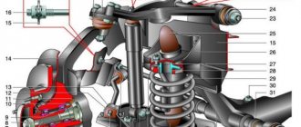
Lever 4 (Fig. 2-86) for controlling the air damper has three profiles. Its outer edge 4.3 acts on the throttle valve control lever 11 through the adjusting screw 10 and ensures the start of a cold engine and the further necessary increase in the engine crankshaft speed. Internal profiles 4.1 and 4.2 act on the lever 6 of the air damper and allow it to open at intermediate positions of the lever 4 by a certain amount. When turning the air damper control lever 4 counterclockwise, the expanding groove releases the pin of the air damper lever 6, and due to the return spring 7, the damper will be held completely closed. At the same time, lever 4 with edge 4.3 slightly opens the throttle valve of the first chamber.
Rice. 2-86. Carburetor starter:
1 – diaphragm; 2 – adjusting screw; 3 – diaphragm rod; 4 – air damper control lever; 4.1 – lower profile of the groove of lever 4 to limit the maximum opening of the air damper; 4.2 – upper profile of the groove, providing mechanical opening of the air damper; 4.3 – edge of lever 4 to ensure starting clearance of the throttle valve of the first chamber; 5 – air damper; 6 – air damper lever; 7 – air damper return spring; 8 – air damper drive cable; 9 – adjusting screw stopper; 10 – adjusting screw for slightly opening the throttle valve of the first chamber; 11 – throttle valve drive lever; 12 – throttle valve of the first chamber; B – starting gap at the air damper; C – starting gap at the throttle valve.
The axis of the air damper 5 is shifted, so after starting the engine the air damper can be opened slightly by the air flow, stretching the spring 7, which ensures a lean mixture.
The vacuum from the throttle space acts on diaphragm 1 and rod 3 slightly opens the air damper. Adjusting screw 2 allows you to adjust the amount of opening of the air damper.
The maximum amount of opening of the air damper when starting and warming up the engine depends on the intermediate positions of the air damper control lever 4 or on the width of the groove of this lever.
Features of the Niva 2121 carburetor
If we are talking about a carburetor, then you should know that this part is so named because its main functional purpose is carburetion or mixing. Indeed, fuel liquid and air are mixed in the carburetor. In addition, the supply of the resulting mixture to the engine cylinders is regulated.
The carburetion mechanism depends on the design of the carburetor device itself. Thus, the “native” carburetor on the Niva 2121 consists of:
- float chamber (the optimal functioning of the idle system and transition systems of all chambers depends on the level of fuel liquid in this device);
- jet (the main metering part through which fuel liquid and air enter the carburetor in metered quantities, they are also called nozzles or plugs);
- diffusers (they are narrowings in the carburetor pipes of both chambers; they are needed to increase the speed of air passage to the mixing chambers);
- throttle valve (mechanical type channel flow regulator, which is intended to change the amount of fuel liquid or gas passing through this channel).
Blocking the second carburetor chamber
The throttle valve of the second chamber can only open when the air damper is open, when the edge of lever 5 (Fig. 2-81) does not rest against pin 2 of the second chamber locking lever.
In this case, when opening the throttle valves, the locking lever acts through lever 14 on lever 13, and the valve of the second chamber opens.
When closing the air damper, lever 5 with its outer edge acts on pin 2 of the locking lever and disconnects lever 14 and the locking lever. Now the throttle valve of the second chamber is blocked and cannot be opened.
How to adjust Ozone
Self-adjustment of the Ozone carburetor on a VAZ 2121 car allows you to achieve stable operation of the power unit and reduce gasoline consumption.
Typically, adjustment work includes adjusting the starting unit, the idle speed unit and the fuel level in the float chamber tank. To quickly carry out the work, it is recommended to immediately prepare the following set of tools:
- multimeter (or tachometer);
- flat narrow screwdriver.
The procedure for performing adjustment work:
- It is necessary to warm up the engine to its operating temperature.
- With the engine running, you will need to fully open the air damper of the carburetor mechanism - fully press the damper drive handle (that is, the choke).
- Turn off the engine.
- Connect the tachometer (multimeter) to the engine: the minus wire to the vehicle ground, the plus wire to the ignition coil to terminal K.
- After connecting, you need to start the engine again, immediately turn on the lighting and the fan to supply heat.
- Use a screwdriver to start adjusting the air-fuel mixture supply screw - you need to turn the screw until the power unit begins to idle smoothly. The optimal tachometer indicator is 750–800 rpm.
- If it is not possible to achieve the desired performance by normal adjustment, you will need to remove the carburetor and thoroughly rinse it from dirt deposits. Apparently, the mechanism is so clogged with sediment coming from the fuel that its adjustment is impossible.
Video: do-it-yourself carburetor adjustment on a Niva
By adjusting or repairing the carburetor with your own hands, the car owner can be confident in the high quality of the work. In addition, a visual inspection of the internal components of the unit will allow you to draw a conclusion about its resource and thus calculate the frequency of maintenance or routine cleaning. Ozone carburetors have been an invariable attribute of Niva cars for many years, ensuring reliable engine operation and excellent operating characteristics.
- Author: ratico19
Rate this article:
- 5
- 4
- 3
- 2
- 1
(17 votes, average: 2.6 out of 5)
Share with your friends!