VaD89RUS › Blog › 20. Diagram of the VAZ 2106 brakes
1. Brake disc;
2. Front brake pad; 3. Piston O-ring; 4. Wheel cylinder piston; 5. Front brake wheel cylinder; 6. Brake hose of the front brake drive circuit; 7. Brake pad mounting pin: 8. Piston stroke limiting screw; 9. O-ring; 10. Thrust cup; 11. Rear brake drive piston; 12. O-ring spring; 13. Bushing; 14. Master cylinder body: 15. Front brake drive piston: 16. Seal; 17. Rod; 18. Vacuum valve; 19. Valve body return spring; 20. Valve body: 21. Diaphragm: 22. Vacuum valve body; 23. Vacuum booster housing cover; 24. Rod buffer; 25. Piston thrust plate; 26. Piston; 27. Vacuum booster valve; 28. Valve spring; 29. Valve return spring; 30. Air filter; 31. Valve pusher; 32. Pedal release spring: 33. Stop light switch tip; 34. Brake light switch; 35. Pressure regulator housing plug; 36. Pressure regulator piston; 37. Housing bushing; 38. Piston head seal: 39. Spring plate; 40. Piston spring; 41. O-ring of the pressure regulator piston; 42. Pressure regulator drive lever; 43. Rear brake pad: 44. Pad tension spring; 45. Rear brake wheel cylinder piston; 46. Piston spacer spring; 47. Wheel cylinder piston seals; 48. Brake pedal; 49. A - Vacuum cavity; 50. B - Channel connecting the vacuum cavity with the internal cavity of the valve; 51. C - Channel connecting the internal cavity of the valve with the atmospheric cavity; 52. D - Atmospheric cavity; 53. K - Hose. connecting the vacuum booster to the engine intake pipe; 54. 1.The pedal is not pressed; 55. 11.Braking; 56.III. The pedal is paused; 57. IV. Disinhibition. When the system is released and the brake pedal, under the action of spring 32, is pulled all the way to the brake light switch 34, then pusher 31 with piston 26 of the vacuum booster is pulled together with the pedal. Valve body 20 and stem 17 are pressed by spring 19 to the rearmost position. In this position, a gap is formed between the valve head 27 and the valve seat, as the piston presses the valve away from the seat. Vacuum cavity A through channel B, the gap between the seat and the valve and then through channel C communicates with the atmospheric cavity D. Therefore, when the engine is running, vacuum from the intake pipe through valve 18 is transmitted to cavity A and through channels and gaps into cavity D. Pistons 11 and 15 of the main cylinder under the action of the return springs are pressed to the rear extreme position until they stop against the locking screws 8, the sealing rings 9 are pressed from the end of the piston groove and through the resulting gaps the working cavities of the cylinder communicate with the hydraulic cylinder reservoir and high-pressure pipelines. Thus, there is no pressure in the brake actuator. Therefore, the pistons 4, under the action of elastic deformation of the sealing rings 3, are retracted inside the cylinders and do not exert pressure on the brake pads of the front brakes, which will be in light contact with the surface of the brake disc. When the car moves without braking, that is, when there is no pressure in the hydraulic drive, the piston 36, under the action of the spring 40 and the torsion lever 42, is raised up until it stops at the plug 35. Therefore, the housing cavities located above and below the piston head communicate freely. This opens up a free passage of fluid to the rear brake wheel cylinders. But since there is no pressure in the entire drive, the brake pads 43 are pressed away from the drums. When braking, when the driver presses the brake pedal, the pusher 31 moves the piston 26. Following the piston, the valve 27 moves under the action of the spring 28 until it stops against the seat of the valve body. When the seat is closed, cavities A and D are separated. With further movement of the piston 26, a gap is formed between it and the flange of the valve 27, through which cavity D communicates with the atmosphere. Outside air enters cavity D through the air filter 30, through the gap between the pusher and the valve and then through channel C. Atmospheric air creates pressure on the diaphragm 21. Due to the difference in pressure in cavities A and D, as well as the force of pressing the brake pedal, the housing the valve moves together with the rod 17, which in turn acts on the piston 15 of the main cylinder. The force acting on the valve body depends on the degree of vacuum in the engine intake pipe and on the force applied to the brake pedal. When the piston 15 moves, the spacer sleeve 13 moves away from the locking screw 8 and the sealing ring 9 is pressed by the spring 12 to the end of the piston groove.
Thus, the compensation gap is closed and the cavities of the cylinder and tank are separated. Therefore, with further movement of the piston 15 in the working cavity of the front brake drive, fluid pressure is created, which is transmitted through pipelines and hoses to the wheel cylinders of the front brakes. It also affects the floating piston 11, which, when moving, creates pressure in the rear brake drive. Under increasing fluid pressure in the working cavities, the front sealing rings of the pistons expand and begin to fit more tightly to the surface of the cylinder and to the end of the grooves, improving the seal of the pistons in the cylinder. Under fluid pressure, the pistons of the 4th and 44th wheel cylinders of the front and rear brakes extend, pressing the pads against the brake disc 1 and the drum. The created braking torques slow down the rotation of the front and rear wheels. At the same time, the load is redistributed along the axles of the car: the load on the front axle increases, and the load on the rear axle decreases. This leads to the rear of the body being raised, that is, the distance between the rear axle beam and the body increases. At the same time, the short arm of the lever 42 is lowered, and the piston 36 of the pressure regulator begins to fall under fluid pressure, compressing the spring 40. At the moment of full braking, the maximum load moves from the rear axle to the front and the greatest lift of the body occurs. The grip of the wheels on the road deteriorates, the pressure of the torsion lever 42 on the piston 36 decreases. Due to the larger area of the end face of the piston head, the force from fluid pressure P2 lowers the piston down until the head comes into contact with seal 38. Further flow of fluid to the wheel cylinders of the rear brakes stops, that is, the braking torque on the rear wheels does not increase, despite pressing the brake pedal firmly and further increase in pressure P, . Therefore, the rear wheels do not lock and the car does not skid. When the brake pedal is released, it returns to its original position under the action of the return spring 32, dragging with it the pusher 31 and the piston 26. The rear end of the piston is pressed against the valve head 27, which leads to the cessation of the flow of atmospheric air into the cavity O. Then the valve head moves away from the seat and cavities A and O communicate, i.e. the pressure in both cavities is equalized, under the action of the spring 19, the valve body with the rod returns to its original position, stopping pressing the piston 15 of the main cylinder. Pistons 11 and 15, under the force of the return springs, are pressed to their extreme position and rest against the locking screws 8. Spacer bushings move the sealing rings 9 away from the end of the grooves, and through the resulting gap the working cavities of the main cylinder communicate with the cavities of the tank. The pistons 4 of the front brake are retracted from the pads due to the elasticity of the sealing rings 3, and the pistons 45 of the rear brake are retracted by the contraction of the tension springs. If the rear brake drive circuit fails due to its leakage, piston 11, under fluid pressure, moves all the way into the master cylinder plug, after which the pressure in the front brake drive circuit begins to increase. Due to the free movement of the piston I, the free travel of the brake pedal increases and only the front brake drive operates. If the front brake drive circuit fails, piston 15 moves forward until it stops against piston 11, after which the rear brake drive circuit begins to operate. The free play of the brake pedal also increases. If any circuit is damaged, the liquid level control lamp lights up, signaling a drop in the liquid level in the tank.
VAZ-2106, master brake cylinder: operating principle, GTZ design, repair
The main brake cylinder on the VAZ-2106 is necessary to create high pressure in the pipe system and on the calipers. This pressure compresses the brake pads, which lock the discs. The brake system is one of the most important, so it must be maintained in good condition. If there is the slightest malfunction, repairs must be made. Quite often, the cause of a breakdown is the gas turbine engine, but before repairing it, you need to make sure that it is the one that is faulty.
Typical malfunctions of the brake system
Before repairing the master cylinder, make sure that the following problems are not present:
- Very often air gets into the hydraulic brake system. As a result, work efficiency decreases several times. Make sure there is no air at all. To do this, you need to bleed the system.
- Carefully examine all elements of the brake system for leaks. If there are any, then it is necessary to replace the damaged elements and completely bleed the system.
- Jamming of the working pistons or the turbocharger can occur due to uneven wear; the problem is solved by completely replacing the turbocharger.
- If the vacuum seal is broken, the brake pedal will be pressed with very great force.
- If the handbrake cable is jammed, the rear wheels may rotate tightly.
As soon as you make sure that all the above malfunctions are absent, you need to turn your attention to the brake cylinder. The cuffs and pistons may fail, resulting in brake fluid leakage. If the return springs are faulty or broken, the pressure in the system will be constantly high. And if there is fluid leakage on it, braking efficiency decreases several times.
GTZ malfunctions
Replacing the VAZ-2107 master brake cylinder is required when this part simply fails. You can determine the malfunction of the GTZ in the following ways:
The red warning light comes on, indicating a problem with the brake mechanism. This lamp comes on when the level in the brake cylinder reservoir drops below normal.
In this case, it is important to find out the reason for the decrease in fluid and, if necessary, add it. If the leak occurs due to a malfunction of the turbocharger, it should be replaced. Presence of leaks on the GTZ If, upon opening the hood, you can see signs of a fresh fluid leak on the GTZ, then it’s time to pay attention to repairing the mechanism
It is possible to repair the main brake cylinder of a VAZ-2107, but at the same time you can extend the life of the product for a short time, the quality of modern spare parts is to blame. If the product fails, or rather, the cuffs and oil seals have dried out, then experienced craftsmen recommend replacing the GTZ. Many desperate amateurs strive to find the answer to the question of how to repair the master brake cylinder, but subsequently everything ends with its replacement.
The GTZ for a VAZ-2107 costs about 500 rubles, so it makes no sense to spend time and money to repair it. Let’s find out in more detail how the GTZ is replaced with a VAZ-2107.
Signs of a broken master cylinder
The main signs characteristic of a breakdown of the main brake cylinder on a VAZ-2106 are the following:
- The presence of traces of brake fluid on the vacuum booster and inside it.
- The brakes cannot be pumped.
- Jamming and sinking of the brake pedal.
- The presence of jerks when pressing the brake pedal.
When repairing the master brake cylinder, there is no need to place the car on an inspection hole or overpass. Everything is done much simpler here. The master cylinder can be replaced by simply opening the hood.
But it’s best to pump the brakes on an overpass. Otherwise, you will need to lift the wheels one by one using a jack. If all work is carried out on a lift or inspection pit, you can not only bleed the system, but also at the same time adjust the tension of the handbrake cable.
How to change a fuse on a Kia Spectra
When the protection element burns out, drivers decide to install a new one with more power. This is a common mistake.
The fuse for the Kia Spectra cigarette lighter is rated at 10A. If you set it to 20A, then in case of overload the wires will melt. The cigarette lighter assembly may burn out, but the element will remain intact. It is not forbidden to use less power, but the devices will constantly burn out.
The protective element is selected according to the current and voltage parameters. The procedure for replacing the distributor in the cabin unit:
- Turn off the ignition and other relays.
- Open the block cover.
- Use special eraser tweezers to pull out the suspicious element.
- They find out why the fuse blew and eliminate the cause.
- Install a new element of a suitable class into the brackets.
The interior block protects the instrument panel lighting, audio system, and signal. If the memory fuse in the power supply is damaged, then the clock, stove, lamps, windshield wipers and power windows will not work.
The fuses in the engine compartment are responsible for the turn signals, high and low beam headlights, and starter.
On the fuse box under the hood of the 2006-2007 Kia Spectra there is a diagram and instructions describing the replacement in Russian.
Act according to the instructions:
- Turn off the ignition.
- Open the block cover.
- An unusable element is detected.
- Find out and eliminate the cause of the breakdown.
- Insert a new fuse.
How to remove the GTZ?
Replacing the master brake cylinder on “sixes” is carried out according to the following scheme:
- Use a bulb to completely drain the fluid from the expansion tank of the brake system.
- Loosen the clamps that secure the hoses coming from the brake fluid reservoir. Please note that if factory compression rings are installed, they may not need to be removed. It is enough to pull the hoses towards you with little effort.
- Using a special wrench, you need to unscrew the brake pipes from the master cylinder.
- Move these tubes so that they do not interfere with the work.
- Using a 13mm wrench, unscrew the two nuts that secure the device to the vacuum booster.
After all this work, you can completely remove the GTZ.
What is needed for pumping?
In order to carry out repairs without problems, you will need a set of standard tools and spare parts
Please note that it is advisable to install new fittings - on old ones the edges wear off very quickly and it is impossible to work with them
For repair you will need:
- A set of wrenches – open-end and socket wrenches for “8” and “10”.
- Balloon.
- Jack.
- Wheel chocks - at least two pieces.
- The supports are several wooden beams.
- Keys to "17" and "13".
- Special wrench “8” and “10” for unscrewing fittings and brake pipes.
You definitely need to purchase penetrating lubricant, prepare a small jar and a transparent tube. The inner diameter of the latter should be the same as the outer diameter of the bleeder fitting.
GTZ repair
To repair the master brake cylinder, you will need to do the following:
- There should be a clean rag on the table on which to place the brake master cylinder body.
- The mechanism has two pistons (that’s exactly how many circuits there are in the brake system). The pistons have slots in the lower parts that limit the stroke inside the cylinder. The pistons are secured using two locking bolts located in the slots.
- Remove the boot and unscrew the bolt that secures the first piston.
- If the piston does not come out under the influence of the spring, you need to lightly press on it so that it sinks a little in the cylinder. After this manipulation, the piston will come out of the cylinder without any problems.
- A similar action is performed for the second cylinder. Unscrew the bolt that secures the element. And in the same way the piston of the second circuit is removed.
- Be sure to place all the elements that you remove from the master cylinder in the order in which you removed them.
- Install new cuffs using the plastic cone included in the repair kit.
The design of the master brake cylinder on the VAZ-2106 is simple, there are only a few key elements in the design. But they affect the functioning of the entire braking system.
Be sure to make sure that the inner surface of the cylinder is perfectly mirror-like. If there are sinks or other damage, it is necessary to replace them - repair is useless. If the inside has taken the shape of an ellipse, then it is unlikely that you will be able to bleed the brake system, and even if you do, the new cuffs will not last long.
Master Cylinder Assembly
Assembly is carried out in reverse order. If you have repaired the main brake cylinder of a VAZ-2106, then you must:
- Install new cuffs.
- Insert the secondary circuit piston and return spring into the cylinder. Before installing them, lubricate the inner surface of the cylinder with brake fluid.
- Secure the position with a bolt.
- Insert the primary circuit piston with the return spring and secure its position with a bolt.
After this, check the tightness of the fixing bolts and install the cylinder:
- Using two nuts, tighten onto the vacuum booster studs.
- Screw the tubes to the GTZ.
- Install the hoses and secure them with clamps.
After all the work has been done, you need to pour liquid into the expansion tank.
↑ Scheme for checking the tightness of the master cylinder
1 — valve for pumping the stand; 2 - pressure gauge; 3 - absorbing cylinder; 4 - main cylinder; 5 - flywheel; 6 — pusher displacement indicator; 7 - tap; 8 - vessel.
Install the master cylinder on the stand and connect it to the stand elements, as shown in Fig.
Open valve 1 to bleed the stand and, moving the master cylinder pistons several times to their full stroke length, bleed the system. Then close valve 1.
Rotating flywheel 5, slowly move the pistons of the main cylinder until the pressure, controlled by pressure gauges 2, reaches 12.5 MPa (125 kgf/cm2). In this position, block the master cylinder pusher. The specified pressure must remain constant for at least 5 s.
In cases of fluid leakage or failure to maintain constant pressure within 5 seconds, replace the cylinder piston seals.
Source
Bleeding the system
The procedure for bleeding the brake system of a VAZ-2106 (like any other car):
- Rear right and left wheels.
- Front right and left.
When working, you move from the far brake mechanism to the near one (relative to the GTZ). Your goal is to get rid of air jams. When pumping, carefully monitor the fluid level in the tank and top up if necessary.
The principle of operation of the master brake cylinder on the VAZ-2106 is that two pistons create pressure in the system. This pressure pushes out the calipers and sets the pads in motion. If there is even a little air in the system, the brakes will not work.
Which wheel to start with?
Let's start the conversation with the sequence, and then move on to a description of the process. You know that the brake system of the VAZ 2107 and other domestic classics has two circuits, or more precisely, three. The first is the front wheels, it consists of two separate lines, it is customary to combine it into one circuit of the front brake mechanisms. The second is the rear wheels. From the main brake cylinder there is one brake pipe going to the “stern” of the car, which is divided into each side of the rear axle. Based on the design, you need to start pumping from the farthest element of the system - the right rear wheel.
Important! Each circuit swings separately, from the beginning we deal exclusively with one, let’s say the rear one, then we move on to the front. If the sequence is violated, problems may arise in the adequacy of the brakes.
Having released the air from the right rear mechanism, we move on to the left rear one. Having finished with it, we move on to the right front, and then to the left front. We start pumping from the farthest section from the GTZ (it is located under the hood on the left side) - this is the rear contour, the right side, then the left, then the farthest section of the front contour - the right side, then the left.
If you replaced the master cylinder, you first need to bleed the air from it
- Fill the brake fluid into the reservoir
- We “fit” the fittings of the brake pipes into the outlet holes of the cylinder. Don't tighten them, just wind them a couple of turns. This is necessary so that air can freely escape from the junction of the tubes and the GTZ housing
- When pouring brake fluid into the reservoir, it can flow out of the fittings by gravity. Otherwise, ask an assistant to press the brake pedal several times. The liquid will not emit a fountain from loosely twisted tubes. First, air will come out, you will see characteristic bubbles, then the liquid itself will begin to ooze.
- Make sure all connections are leaking evenly. Only after this do we tighten the fittings of the lines and wipe these places with a dry cloth
Video on how to bleed the master brake cylinder or why the system is not bleeding:
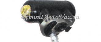
Where is the brake cylinder of the VAZ 2106
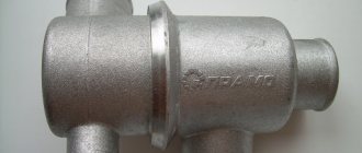
The brake master cylinder is installed in the engine compartment of the VAZ 2106, above the engine. The device is located about half a meter from the driver. Just above the cylinder there is a small expansion tank into which brake fluid is poured.
The cylinder has an oblong shape. The body is made of high quality steel.
The housing has several threaded holes for screwing in contour brake pipes. This device is screwed directly to the brake booster using two 8mm bolts.
Main function of the cylinder
In short, the function of the master brake cylinder is reduced to the timely redistribution of brake fluid between several brake circuits. There are three such circuits on the “six”.
There is one circuit for each front wheel, plus a circuit for servicing the two rear wheels. It is from the master brake cylinder that the fluid comes, which then begins to put pressure on the wheel cylinders, forcing them to tightly compress the brake pads and stop the car. In addition, the master cylinder performs two additional functions:
- abductor function. If the brake fluid has not been completely used by the working cylinders, then the remainder goes back into the reservoir until the next braking;
- return function. When the driver stops braking and removes his foot from the pedal, the pedal rises to its original position under the action of the master cylinder.
How the cylinder works and how it works
The VAZ 2106 drive cylinder has a lot of small parts, so at first glance the device seems very complex. Nevertheless, there is nothing complicated about it. Let's list the main elements.
- The case is steel with two internal chambers.
- Washer fixing the main fitting.
- Brake fluid drain fitting (it connects directly to the expansion tank).
- Union seal.
- Washer for the limit screw.
- Stopper screw for brake piston.
- Return spring.
- Support cap.
- Compensator spring.
- O-ring for the brake piston (there are 4 such rings in the cylinder).
- Spacer washer.
- Rear brake circuit piston.
- Small spacer washer.
- Front brake piston.
A steel plug is installed at one end of the cylinder body. The second end is equipped with a flange with mounting holes. And the master cylinder works as follows:
- Before pressing the pedal, the pistons stand in the cylinder body at the walls of their chambers. Each spacer ring is restrained by its own limiting screw, and the chambers themselves are filled with brake fluid;
- after the driver, by pressing the pedal, releases the entire free play of this pedal (this is approximately 7–8 mm), the pusher in the cylinder begins to put pressure on the main piston, moving it to the opposite wall of the chamber. At the same time, a special cuff blocks the hole through which the brake fluid goes into the reservoir;
- when the main piston reaches the opposite wall of the chamber and squeezes out all the liquid into the hoses, an additional piston is activated, which is responsible for increasing the pressure in the rear circuit. As a result, the pressure in all brake circuits increases almost simultaneously, which allows the driver to use both front and rear pads for braking;
- As soon as the driver releases the brakes, the springs return the pistons back to their starting point. If the pressure in the cylinder was too high and not all of the liquid was consumed, then its remains are drained into the tank through the outlet hose.
Video: principles of operation of brake cylinders
Replacing the rear brake pads of a VAZ 2107
Removal
This can be done both in the pit and on a lift. The main thing is to gain access to the torso of the handbrake. We put the “shoes” under the front wheels and get started.
Important! To change the rear pads, you need to remove the drum, and to do this, you cannot put the car on the handbrake or raise the handbrake lever to the top position. In this case, they will spread out in different directions, press against the walls of the drum and it will not be possible to remove it.
If you change pads, no matter the front or rear brakes, always change them in pairs - on two wheels of the same axle. Thus, there will be uniform wear and the wheels will brake with equal efficiency. Otherwise, you may spin out during emergency braking.
- Release the cable for adjusting the handbrake tension.
This is necessary so that the pads are not separated. Even a slight dilution can make it difficult to remove the brake drum. Let us remind you that the cable adjusting nuts are located under the car, in the center under the bottom. They are easy to find, one cable runs from the front of the car, and through these nuts it splits into two rear wheels.
- We hang the wheel, put stops under the front wheels, remove the wheel
- We clean the contact area between the drum and the axle shaft from dirt and rust.
You can use a metal brush or knife. We fill this place with WD-40; if it is not there, we make a WD-40 with our own hands and wait.
- We unscrew the guide pins and try to remove the drum from the axle shaft.
Often a bummer awaits us at this stage. He may get stuck well and won’t want to take off. In severe cases, he does not even move, there is no backlash. What to do in this case?
There is a folk method. In order to move the drum at least a little and rip it off the axle shaft, you need to start the car and accelerate the car into second gear as hard as possible and sharply press the brake. In most cases, the drum will fall off the axle shaft, sometimes it will fly out in the direction the wheels are moving.
Let's move on to the second stage of removal. The drum has some play, wobbles, spins around its axis, but does not want to come off the brake mechanism. In this case, you can use an impact tool - a hammer or use bolts as pullers.
The first option is more rigid, there is a chance of damaging the drum or splitting it into pieces. We climb into the hole, take a wooden block, place it against the edges of the drum and tap it with a hammer. Make a couple of blows on one side, turn the drum, make a few precise blows on the other side. Thus, it will gradually come off the brake pads. The main thing is that he doesn’t go skewed and catch the wedge.
The second option is bolts, like pullers. When unscrewing the guide pins, pay attention to the technological holes in the drum. They, unlike the holes for the pins, are threaded. We select bolts of the required diameter, usually “13”, and screw them in. We begin to tighten them evenly. They rest against the axle shaft, we twist them further. They pull the drum from the brake mechanism along the thread.
Important! The second option can be used if there is play in the drum and it rotates freely around the axle axis. Otherwise, you can “turn” the head of the bolts without achieving results.
Video on how to remove a brake drum, method 1 - severe case:
Video on how to remove a “stuck” drum using bolts as pullers (Method 2):
- Remove the washers of the support cups.
For ease of dismantling, it is recommended to start with a pad without a handbrake lever. Scroll the top washer until the pin matches the slot in it.
Important! The spring of the support cup is elastic and can fly out in an unknown direction. As a result, there is loss of washers, springs, and the problem of inserting the dropped pin into the hole in the protective shield. We hold them with our hands, and you will be happy.
- Using pliers, remove the lower tension spring. It can also fly to the other side of the garage; we hold it or monitor the place of its fall.
- We take the block in our hands and pull it to the side, removing it from the upper spring.
- Remove the upper spring completely and pull out the spacer bar.
We repeat the operation for the opposite block. Pull it to the side and remove the handbrake cable fastening from the lower end. This is clearly shown in the video below.
Important! When dismantling the pads, it is recommended to hold the pins of the support cups with your finger or other improvised means. Otherwise, they may fall out of their seats. Returning them to their place, especially the one located on the side of the rear suspension transverse link, will be problematic.
What to do if the pin does fall out? You can use a screwdriver and “such and such” to insert it through the hole for fastening the rod and the protective shield. You can tie a thin wire to the end of the pin, which should be on the side of the brake pads. Pass it through the holes and pull it through, pointing the pin into the holes and pulling it out.
Which cylinder to choose for installation
A driver who decides to replace the brake master cylinder will inevitably face the problem of choice. Practice shows that the best option is to install an original VAZ cylinder purchased from an official auto parts dealer. The original cylinder number in the catalog is 2101–350–500–8.
However, it is not always possible to find such a cylinder, even from official dealers. The fact is that the VAZ 2106 was discontinued a long time ago. And spare parts for this car are becoming increasingly rare on sale. If this is the situation, then it makes sense to look at the products of other manufacturers of cylinders for the VAZ classics. Here they are:
The products of these companies are in high demand among owners of "sixes", although the price of cylinders from these manufacturers is often unreasonably inflated.
I once had the opportunity to compare prices of brake cylinders from different manufacturers. That was six months ago, but I don’t think the situation has changed much since then. When I went to a spare parts store, I found an original VAZ cylinder on the counter, which cost 520 rubles. Nearby lay a Belmag worth 734 rubles. A little further along were the LPR and Fenox cylinders. LPR cost 820 rubles, and Fenox - 860. After talking with the seller, I found out that original VAZ cylinders and LPR cylinders are in greatest demand among people, despite their high cost. But for some reason the “Belmags” and “Phoenoxes” were not dismantled so actively.
Signs of cylinder failure and checking its serviceability
The driver should immediately check the brake cylinder if he notices any of the following warning signs:
- a light flashed on the dashboard, signaling that the level of brake fluid in the reservoir had decreased;
- the free play of the brake pedal has become longer or the pedal has generally begun to sink into the floor of the cabin;
- braking has become uneven: when you press the pedal, the car pulls to the side;
- it has become more difficult to brake: even if the pedal is completely recessed into the floor of the cabin, the car does not stop completely.
All these points indicate that there is something wrong with the drive cylinder, and you need to figure out this problem as soon as possible. Here's how to do it:
- The first and easiest way to diagnose a cylinder is a routine inspection. If brake fluid leaks are visible on the cylinder body, the problem has been found. When the seals in the cylinder lose their tightness, fluid begins to flow either to the vacuum booster or to the spar under the cylinder. In all these cases, the cylinder will have to be removed and disassembled;
There is another, more complex way to check the cylinder. Let us list its main stages.
- Using a 10mm open-end wrench, unscrew all the contour hoses from the cylinder. In their place, bolts of 8 are screwed in, which will serve as plugs.
How to bleed your brakes yourself?
There are several ways, we’ll talk about each specifically.
Method 1 – lid with nipple
For this method we will need to make one “homemade product”. We take an unnecessary cap from the brake fluid reservoir or from the clutch reservoir (the caps have the same thread and diameter). We buy a nipple for the camera and unscrew the nipple from it. We make a hole in the lid to secure the purchased nipple in it. We carefully glue it to avoid air leakage from the attachment points.
Video on how to make it:
We take a hose whose inner diameter should match the diameter of the nipple on the lid. The length should be enough to reach them from the barrel to the car wheel. Let's start the process.
- Remove the cap with the level sensor from the brake fluid reservoir. Screw in the homemade product instead
- We take a hose and put it on the nipple of a homemade lid
- We clamp the hose with a clamp or other fastener. This will help control the air supply in the barrel. You need to create pressure - release the clamp, no - clamp the hose
- We unscrew the nipple from the left front wheel or spare tire. We put a hose on it. It is advisable to keep the pressure in the wheel chamber at about 2 atm.
- We release the clamp and go to bleed the brakes ourselves according to the scheme outlined at the beginning of the article.
- Having bled the air from their system, we disassemble the circuit. Don’t forget to return the original cap with the level sensor to the brake barrel.
This method is good if you need to pump one of the elements of the system where the amount of air is small. Do not forget that when pumping, you always need to monitor the level of brake fluid in the barrel. Therefore, if you pump the entire system in this way, then you will have to constantly unscrew the cap and check the level and top it up if necessary. This is where a clamp comes in handy so as not to release all the pressure from the chamber. Agree, this is inconvenient.
Method 2 - gas stop or stick
I do everything the same as with an assistant. Only instead of his leg we use improvised means: a gas stop, if the car has one, or a stick of suitable length. We independently press the pedal several times and press it with what you have. You can rest it on the driver's seat so that the brake always remains pressed. We climb into the hole and pump up what you need.
Important! With this method, when you unscrew the cylinder bleeder fitting, the pressure in the system will drop and there is a possibility that the stick or stop will come off the pedal. It will return to its original position. This is fraught with air being sucked into the system through the fitting you opened. This is suitable for bleeding air from one specific brake mechanism; it is not suitable for the entire system.
Method 3 - gravity
This option can only be used for front brakes. Its meaning is that by unscrewing the brake hose, the fluid will fill it by gravity. Having screwed it into the seat on the caliper, unscrew the “bleeder” fitting and wait until brake fluid flows from it. Thus, you smoothly, by gravity, fill the cylinder with liquid; it itself should expel all the air. But don’t forget to monitor the level in the barrel.
This method can be used if you pump only the front brakes . It is not suitable for the rear contour. The pressure of the brake fluid water column is not enough to push air out of the distant elements of the system.
Replacing the master cylinder of the VAZ 2106 brakes
In the vast majority of cases, replacing the cylinder is the best repair option. The fact is that it is not always possible to find individual parts of brake cylinders (pistons, return springs, spacers, etc.) on sale. It is much more common to find sets of seals for cylinders on sale, but the quality of these seals sometimes leaves much to be desired. In addition, they are often counterfeited. That is why car owners prefer not to bother with repairing the old cylinder, but simply install a new one on their “six”. To do this, we will need the following tools:
- set of spanners;
- pliers;
- flat screwdriver;
- rags;
- medical syringe;
- canister of brake fluid (capacity 0.5 liters);
- 5 x 6 bolts (they will be used as plugs for the brake hoses).
How to remove air from the brake system
When the driver changes the drive cylinder, air enters the brake system. It's almost inevitable. Air bubbles accumulate in the brake hoses, making normal braking difficult. So the driver will have to remove air from the system using the recommendations outlined below. It should be noted here that to perform this operation you will need the help of a partner.
- The front wheel of the car is jacked up and removed. Access to the brake fitting is provided. A piece of plastic tube is put on it. Its second end is directed into an empty bottle. Then the nut on the fitting is carefully unscrewed.
Video: bleeding classic brakes without the help of a partner
So, the brake cylinder on the “six” is an extremely important part, on the condition of which the life of the driver and passengers depends. But even a novice car enthusiast can change this part. No special skills or knowledge are required for this. All you need is to be able to hold a wrench in your hands and strictly follow the recommendations outlined above.
Main brake cylinder: diagram and principle of operation
The brake system of a car consists of many elements and components, the most important of which is the main brake cylinder. It is the structural central element in the service brake system. Its diagram and operating principle are described here.
The brake system of a car consists of many elements and components, the most important of which is the main brake cylinder. It is the structural central element in the service brake system. It is needed in order to convert into hydraulic pressure the forces that are applied in the braking system to the brake pedal.
The main two-section brake cylinder is usually installed on modern cars. The brake mechanisms of the left rear wheel and the right front wheel, in front-wheel drive cars, are combined by one of the circuits, and the right rear wheel and the left front wheel are united by the second. The brake operating system in cars that have rear-wheel drive is built on a different principle. The second circuit serves the rear wheels, and the first circuit serves the front wheels.
The master cylinder is secured to the vacuum brake booster, namely on its cover. A reservoir with two sections containing a certain supply of brake fluid is connected to the bypass and compensation holes, sections of the master cylinder, and is located above the cylinder itself. It is needed in order to replenish its supply in case of evaporation or leakage of brake fluid. For the convenience of measuring the level of such fluid, control marks are applied to the walls of the tank, which are transparent (usually “MIN” and “MAX”), and there is also a sensor in the tank that shows the brake fluid level. If the level drops below that set on the dashboard, then the warning light on the instrument panel makes itself known.
Master cylinder: its purpose and functions
During the braking process, the driver directly acts on the brake pedal, which is transmitted to the pistons of the master cylinder. The pistons, acting on the brake fluid, actuate the working brake cylinders. From these, in turn, pistons extend, pressing the brake pads to the drums or discs. The operation of the brake master cylinder is based on the property of brake fluid not to be compressed under the influence of external forces, but to transmit pressure.
The master cylinder performs the following functions:
- transmission of mechanical force from the brake pedal using brake fluid to the working cylinders;
- ensuring effective braking of the car.
In order to increase the level of safety and ensure maximum system reliability, two-section master cylinders are installed. Each section serves its own hydraulic circuit. In rear-wheel drive cars, the first circuit is responsible for the brakes of the front wheels, the second - the rear. In a front-wheel drive car, the brakes of the right front and left rear wheels are served by the first circuit. The second is responsible for the brakes of the left front and right rear wheels. This scheme is called diagonal and is most widespread.
Car brake master cylinder diagram
In the body of such a cylinder, two pistons (12 and 18) are placed, which are located one after the other. The second piston is freely installed, while the first piston interacts with the brake booster rod, which abuts against it. Rubber cuffs perform the functions of piston seals, which, as is already known, are located in the cylinder body. Return springs (2 pieces “9, 14”) hold and return the pistons.
How the main brake cylinder works and how it works
When braking occurs, the first piston is pushed by the rod of the vacuum brake booster. When the piston moves along the cylinder, it closes the hole, which is a compensation hole, because of this, the pressure in the first circuit increases accordingly, as a result of which the second circuit moves, which also leads to an increase in pressure in it. Brake fluid, through the bypass hole, fills the voids that arise when the pistons begin to move. The return spring controls the movement of both pistons and the activation of the brake mechanisms, due to the maximum pressure that is created in the circuits.
The pistons return to their original position when braking is completed. The pressure in the circuit is equalized with atmospheric pressure; this occurs during the passage of the piston through the compensation hole. The brake fluid that fills the cavities prevents the vacuum that could occur in the operating circuits when the brake pedal is suddenly released. When the piston moves, the liquid returns through the bypass hole back into the tank.
Despite the possible leak of brake fluid in one circuit, the second circuit will not stop working. If such a leak occurs in the first circuit, then it makes the movement that occurs in the cylinder and comes into contact with the second piston, and it, in turn, ensures activation in the second circuit of the brake mechanisms through its movement.
When a leak occurs in the second circuit, the brake cylinder works differently, namely, the second “pusher” begins to move with the help of the first, its movements are unhindered, and are only limited by stopping at the end of the cylinder body. Due to the increase in pressure in the primary circuit, the car slows down. Braking is quite effective, despite the increased brake pedal travel, which occurs when there is a fluid leak. If obvious problems are noticed with the brake system, then you need to begin inspecting the brake system and, if necessary, replace this cylinder. For more details, read the article: “How to change the brake master cylinder.”
Video about brake master cylinder:
When product replacement is required
Both the front and rear wheels are characterized by the use of 4 brake pads to ensure effective braking. These products differ only in design, although the principle of operation is similar.
The rear pads of the VAZ 2107 are presented in the form of an arched steel structure, on the outer part of which a friction layer is applied. It is due to the friction of this layer against the inside of the drum that the car stops. If you do not replace the brake elements in a timely manner, this will be fraught with the development of unpredictable consequences, because the most important thing for any car is the serviceability of the braking system.
It is necessary to change the rear brake pads on a VAZ-2107 when the friction lining wears down to a thickness of less than 1.5 mm. It will not be possible to determine this fact without removing the wheel and dismantling the drum. But this is one of the main ways to determine whether the brake system is faulty. There is a second option, which is more convenient and does not require dismantling the rear wheel. To do this, you need to listen for signs of squeaking of the rear wheels, as well as grinding and lack of braking effect, but this can lead to damage to the drum itself. You can squeeze the handbrake while standing on a slope and check that it is working correctly. Of course, the cable on the handbrake may become loose, but if you tighten it and still have no effect, then it’s time to start replacing the pads. If the rear brakes are not functioning, then it is time to change the pads. It is recommended to change them as a set on both rear wheels, since they are often worn out at the same time. What is the process of replacing rear brake pads on a VAZ-2107 will be determined further.
Features of replacing rear pads
At the beginning of the work, it should be noted that the handbrake must initially be lowered to its lowest position. This will allow you to dismantle the brake drum and thereby get to the worn parts. To begin replacing the brake pads of a VAZ 2107, it is necessary to remove the rear wheel:
- There is a drum behind the wheel, which also needs to be removed. There are no problems with this, so we move on.
- After removing the drum, it is necessary to inspect the worn pads. If the thickness of the friction lining exceeds 1.5 mm, then there is no need to replace the products. Before carrying out further work, it is necessary to clean the mechanism from dirt and dust. To do this, you can use a brush or cloth.
- If the products need to be replaced, then you need to take a screwdriver and then remove first the upper, then the lower connecting springs. If you can’t dismantle it with a screwdriver, then you should use pliers. The photo below shows the springs that should be removed.
- Next, you need to remove the clamps, which consist of a rod, a washer and a spring. These washers must be rotated 90 degrees to remove them through the slots. This is what the washers that hold the pads look like.
- Similar procedures are carried out with the second block.
- After removing the springs and clamps, the pads are removed independently.
- The parking brake locking pin is straightened. The photo below shows the location of the locking pin. Now you need to unscrew the parking brake lever. This can be done using pliers. After this, the washer is removed, then the lever.
- During the dismantling process, you will have a question, what to do with the parking brake tip? It must be disconnected from the product and then left hanging.
- If necessary, it is recommended to replace all parking brake parts that were removed from the old product with new ones.