It all started when a friend and I decided to tune the headlights on his car. Seryoga wanted xenon lenses, and I convinced him to also get angel eyes... In the end, they also decided to make LED turn signals. They did everything for a long time and tediously) But they finally did it. And now we need to solve a couple more issues... one of which is the turn signal relay. And so to the point!
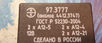
We disassembled the relay. There's a circuit that switches the relay. It is based on a specialized U643B controller from Atmel. As it turned out, many relays are produced precisely on the basis of this microcircuit or its analogues.
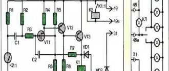
The controller has the function of signaling a malfunction of the direction indicator lamps. It detects a malfunction very simply - based on the current in the circuit. If the lamp burns out, the current decreases and the turn signal switching frequency increases.
The value of the current flowing through the direction indicator circuit is recorded by pin 7 of the microcircuit, which is called Lamp failure detection.
As you know, the efficiency of LEDs is much higher than that of incandescent lamps. Accordingly, they consume less current. Therefore, the installation of LED bulbs in turns is perceived as a malfunction in the circuit, and the turn signal relay increases the switching frequency.
The malfunction is detected by the voltage drop across resistor R3. If insufficient power is released on it, the controller will go into emergency mode) Therefore, for normal operation of LED lamps in turns, you need to increase the resistance of this resistor so that the same voltage is released on it as for conventional incandescent lamps.
There are two ways to solve this problem: cut the current measurement circuit (pin 7) or select the resistance of resistor R3 and replace it. The first option is more accessible) although the second is more correct. For now, let's take the path of "least resistance", arm ourselves with a scalpel and cut the conductor on the relay board!
You need to cut here! It is advisable to insulate the incision site, for example with nail polish.
The result did not completely satisfy us. Seryoga thinks that the turn signals work too quickly. You can slow down the process by changing the values of the elements of the reference circuit of the pulse generator R1 C1.
We decided not to bother with the R3 shunt. There the resistance is very small, without precise instruments it’s impossible to find one. So we'll tinker with R1. It will be easier with resistors than with conductors.
As standard, a 91KΩ resistor is installed in the relay. We purchased a multi-turn resistor with a nominal value of 100K and soldered it in place of the original one. Then we connected the relay to the power supply, attached a light bulb to the contacts and rotated the resistor until the switching frequency became satisfactory!
The multi-turn tuning resistor has three flexible terminals. The extreme ones are the resistance itself (resistor), and the middle terminal is a slider. One of the outer terminals can be cut off. In place of the standard resistor, we solder the middle and one of the outer terminals of the new trimming resistor into the board.
In the photo, the resistor in the upper right corner is blue.
Read more: Replacing the front wheel bearing of a gazelle video
I was looking for information on the Internet. No one, apparently, deals with such matters. Or he does it on the sly. So I decided to make a short report on making a relay for the Blazer s10 from a relay from a VAZ.
We will do it as expected, with the possibility of subsequent replacement.
What will you need? VAZ 3-pin turn signal relay.
Connector for lamp H4 (ideal for this relay))
Well, and also a soldering iron, tin, acid (NOT rosin)
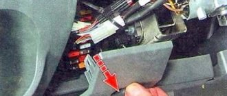
First, let's disassemble the original Blazer relay...
We cut off this very mechanism with side cutters so that small legs for soldering remain...
Now we correlate 2 relays...
Bimetallic relay - 2 contacts. operating principle - the plate heats up - opens the contact, cools down - closes the contact. The higher the WATT rating of the lamps, the more often it blinks, but lamps on sale only have a power of 5 watts, so for me personally, it blinked very slowly. As a temporary solution, I connected one more lamp to the front turn signal, but sometimes the relay overheats and stops working. This often happens when you stand at a traffic light for a very long time with the turn signal on... And, of course, you can’t connect the LED lamps...
And so, we carefully look at the photo - it shows where the 12 volt input is, and where the output for the turn signals is...
Now let's look at a 3-pin relay. It, unlike the 2-pin one, has power, when supplied, a uniform opening and closing of the contacts is observed, regardless of the WATT rating of the lamps. You can even install LEDs.
So. let's move on. We cut the wires of the relay connector “+” and “L” by about 3-4 cm. We solder the “+” socket of the new relay to the leg of the round relay called “+” incoming. I have a blue wire on the plug.
We solder the connector wire marked “L” to the second leg of the round relay. I have a red wire on the connector.
there should be such a device))
Now we make a small cutout on the free side of the connector for the wiring. There is enough space for them inside...
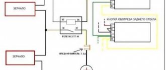
All drivers are required to indicate maneuvers on the road by turning on the direction indicator. This flashing signal is found in every car. Its operating mode creates a turn relay, the circuit of which supplies current to the light bulbs and causes them to blink. At the same time, an audible signal sounds in the form of clicks, reminding you that the direction indicator is on. All these actions are provided by a special turn relay circuit.
Among various designs, electromagnetic-thermal and electronic relays are most widespread. The latest devices are considered more modern and are installed on all later car models.
What is a turn relay?
Turn relay (turn signal breaker relay, current breaker) is an electrical or electronic device designed to close and open the circuit of a vehicle's light direction indicators in order to generate an intermittent signal to warn that the vehicle is performing certain maneuvers.
This device has four main functions:
- Formation of an intermittent signal from the direction indicator lights on one side of the car (on the right or left) when performing the corresponding maneuvers;
- Formation of an intermittent signal of all direction indicator lights when the hazard warning lights are turned on;
- Formation of an intermittent signal from the corresponding warning lamp on the dashboard;
- Generating an intermittent sound signal informing the driver that the direction indicators are on.
The breaker relay is part of three electrical circuits: two turn signal light circuits on the right and left sides of the vehicle, and one hazard warning circuit (which includes turn signal lights on both sides of the vehicle). To turn on the light alarm, the relay is connected to the corresponding circuit using the steering column switch. Therefore, usually only one turn relay is installed on vehicles.
Current traffic rules and standards establish that all motor vehicles operating on the territory of the Russian Federation must be equipped with direction indicators, and the use of this signaling is mandatory when performing any maneuvers. If the light alarm is not working, it is necessary to take measures to eliminate the malfunction; most often, repairs come down to simply replacing the turn signal breaker relay. But before you buy and change a relay, you need to understand the types of these devices that exist today, their design and characteristics.
Classification, design and principle of operation of the turn relay
Two main types of relays are used on cars, tractors and other equipment:
Devices of these types differ in the physical operating principles embedded in them and, accordingly, in their design.
Electromagnetic thermal current interrupters. These are turn relays of an old design, which have been used on cars for several decades, but thanks to their simple design and reliability, they have not yet lost their relevance.
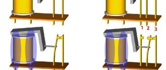
The basis of this device is an electromagnetic core with a coil and two steel armatures with contact groups. One armature is pulled away from its contact by a thin string of nichrome (a metal with high resistivity and a high coefficient of thermal expansion), the second armature is held at some distance from its contact by a springy bronze plate. The operation of this type of relay is quite simple. When the turn indicators are turned on, current flows through the core winding, nichrome string and resistor, the resistance of this circuit is high, so the lamps glow at full intensity. Within a short time, the string heats up and, due to thermal expansion, lengthens - the armature is attracted to its contact and closes the circuit - in this case, the current flows bypassing the string and the resistor, the turn signal lamps glow at full intensity. The de-energized string quickly cools, shortens and pulls the armature away from the contact - the circuit breaks, the current flows along the string again and the process repeats.
At the moment the contacts close, a large current flows through the electromagnetic core, a magnetic field is formed around it, which attracts the second armature - the second group of contacts is closed, which turns on the lamp on the dashboard. Thanks to this, the operation of the direction indicators is duplicated by the intermittent operation of the lamp on the dashboard. The described processes can occur with a frequency of 60-120 times per minute (that is, each cycle of heating and cooling of the string takes from 0.5 to 1 second).
How does an electromagnetic-thermal relay work?
These devices are no longer used in modern cars. However, in older models they are still widely used.
The design of the electromagnetic-thermal relay is quite simple; it uses a circuit for connecting turn signals through an electromagnetic-type relay. It is made in the form of a cylindrical core, and a thin copper wire is used as its winding. At the top of the core there are two groups of contacts, and metal anchors are installed on each side. The first group of contacts closes the circuit where there is a control light located on the instrument panel. With the help of other contacts, the circuit with the lamps in the direction indicators is closed. They are the ones who provide the flashing mode.
Read more: Charger for Nissan Leaf
A thin nichrome string is attached to the anchor of the main group of contacts. It pulls the armature away from the contact, which is located on the core. Thus, the circuit will be open, which is its normal position. The core itself is installed on a special insulated platform, where the opposite end of the string is also fastened. During operation, an electric current passes through the string, since it, together with the resistor, is in the switch circuit. All elements of the device are housed in a cylindrical metal case.
The operating principle of an electromagnetic-thermal relay is very simple. When the turn signal is turned on, the circuit is completed. Under the influence of current, the nichrome string heats up and its length increases. The anchor, which was previously pulled back, is attracted by the core, straightens and closes the contacts for a short time. Because of this, the turn signal lamps begin to shine at full intensity. The current passes by the string, causing it to cool and shorten again. As a result, the armature is pulled away from the core, which leads to the opening of the contacts. The lamps stop shining, then the whole cycle resumes. The nichrome string heats up and cools down very quickly, ensuring that the lamps blink at an average frequency of 60-120 times per minute.
The blinking of the light located on the panel is also associated with the operation of the main group of contacts. Therefore it works synchronously with the warning lamps. Mini-audio signals in the form of characteristic clicks appear when the armature and contacts close and open, hitting each other.
A significant disadvantage of this device is the gradual stretching of the string, which disrupts the normal operation of the relay. Therefore, these devices are now being replaced by more modern electronic relay designs.
Questions regarding the correct purchase and replacement of a turn relay
Relay failure is one of the common problems with the electrical system of cars, and although the rules of the road do not prohibit the operation of a vehicle with faulty turn indicators (as the signals can be given by hand), this part should be replaced as soon as possible if it breaks down. For replacement, you need to choose a relay of the same type and model that was previously installed on the car. However, today there are many analogues of the most common turn relays on the market, and among them you can choose the right device. To make the right choice, you need to consider the following:
- Supply voltage - the relay must correspond to the power supply of the vehicle (12 or 24 volts);
- Number and location of contacts (pinout) - the relay must fit into its place in the relay and fuse block or in a separate connector without any modifications;
- Case dimensions - the relay should not exceed the dimensions of the relay and fuse box (although there are exceptions).
Modern relays are easy to change - you need to open the relay and fuse box, remove the old relay, clean the electrical connector if necessary (remove dirt and dust), and insert a new relay. Electromagnetic-thermal type breakers with screw connectors require more manipulations: you need to loosen the nuts of the old relay, remove the wires and fix them on the new relay. In this case, the relay itself is usually mounted on the body using a bracket and a bolt. In some cases, electromagnetic thermal relays allow changing the frequency of current interruption - to do this, the device must be disassembled and adjusted by turning the screw that tensions the nichrome string.
If correctly selected and installed, the relay will immediately begin to work, ensuring compliance with traffic rules.
Relay and its use in car alarms
How to turn a “minus” into a “plus” and vice versa?
How to hook up to an electric drive? How to open the trunk with the alarm key fob? How to block the engine from starting? There is an answer to all these questions: using a relay. Knowing how a relay works, you can implement various connection schemes to the car's electrical wiring.
Usually the relay has 5 contacts (there are also 4-pin and 7-pin, etc.). If you look at the relay carefully, you will see that all contacts are signed. Each contact has its own designation. 30, 85, 86, 87 and 87A. The figure shows where and what contact is.
Pins 85 and 86 are the coil. Contact 30 is a common contact, contact 87A is a normally closed contact, contact 87 is a normally open contact.
At rest, i.e., when there is no power to the coil, contact 30 is closed with contact 87A. When power is simultaneously supplied to contacts 85 and 86 (one contact is “plus” and the other is “minus”, no matter where it is), the coil is “excited”, that is, it is triggered. Then contact 30 is disconnected from contact 87A and connected to contact 87. That’s the whole principle of operation. It seems to be nothing complicated.
A relay often comes to the rescue when installing additional equipment. Let's look at the simplest examples of using relays.
What is a turn signal switch used for?
Traffic regulations indicate that each driver, planning to perform a particular maneuver, is obliged to notify other drivers of his intentions. Once upon a time, when cars were still a curiosity, such notifications were given with the left hand (when driving on the right). If the arm was extended, this meant the driver wanted to turn left when it was bent and the fingers were pointing up - to the right.
With the increase in the number of cars, traffic rules and lighting devices were improved, not only making it easier to move in the dark or in conditions of reduced visibility, but also signaling to other participants about a change or suspension of movement.
Traffic change signal
Cars began to be equipped with light direction indicators, which were supposed to pulsate to attract attention. To prevent the devices from constantly shining, but from blinking periodically, a small device was invented, which later became known as a pointer breaker or rotary relay. Despite the fairly large number of varieties of the mentioned device, their functions are similar: supplying a pulsating impulse to the turn signal lamps and signaling with clicks that they are on.
Types of breakers and their features
Modern rotary relays are mainly divided into two types: thermoelectromagnetic and electronic. Each device has its own advantages and disadvantages, and this will be discussed. Thermal electromagnetic relays contain a core with two contact groups and side armatures. In addition, they have a copper wire winding. The contacts leading to the light bulbs are connected to a thin nichrome wire, which, in turn, is connected to a plate that is connected to the core.
In the normal state, when no current flows into the circuit, the plate is not adjacent to its base. When the electrons begin to move, the nichrome wire heats up, elongates, and shorts the core plate. The lights come on. Afterwards, the nichrome cools down, the plate comes off again, the current changes direction, and the light bulbs burn at full intensity. Since the cooling-heating process occurs quite quickly, 1-2 times per second, the turn signals blink. Since the light bulb located on the instrument panel is also connected to the circuit, it also begins to pulsate. The specific clicking of the breaker is a consequence of the cyclic impacts of the armatures on the contacts.
Flashing car turn signals
A relay of this type was installed on all cars for quite a long time, but it had (and has) a significant drawback. Over time, the nichrome wire stretches and the turn signals no longer work. Besides this, there is another point. If one of the light bulbs burns out, the load on the others increases significantly. In recent years, thermoelectromagnetic relays are practically no longer installed on cars. They have been replaced by more reliable electronic breakers.
Electronic turn signal relays are built on the same principle as thermal ones, but instead of a nichrome wire, there is an electronic circuit made of transistors. The control chip contains an algorithm that produces automatic pulses that, at certain moments, supply current to the core winding. The operation of the device itself is as follows: after voltage is applied to the transistors, frequency pulses are sent from them, having the oscillations that are set by the program in the microcircuit. As the current passes through the circuit, it attracts the armature, closing the contacts leading to the lighting fixtures, causing the bulbs to light up. Since the cycle consists of signals of different frequencies, they either work at full intensity or dim.
Electronic relay: circuit and principle of operation
The design of the electronic turn signal relay consists of two main parts. From a standard electromagnetic relay that performs switching and an electronic key that provides a certain frequency of operation of this device.
The nichrome string has been replaced with an electronic key. With its help, voltage is supplied and removed from the winding of the electromagnetic relay at certain intervals. The key is based on microcircuits or discrete elements. They are components of the master oscillator and control circuits.
The operating principle of an electronic relay is very simple. When voltage is applied to the relay, the master generator is switched on. With its help, control pulses with different frequencies are generated, which are supplied to the control circuits. By means of pulses, the current passing through the winding of the electromagnetic relay is supplied or interrupted. Such actions cause the anchor to alternately attract or lower. As a result, the contact groups close or open at a certain frequency, ensuring the same flashing of the signal lamps.
All electronic elements of the relay are mounted on a separate board. The electromagnetic relay is located above the board. Both of them are housed in a plastic case. The contacts are brought out from below or from the side. For fastening the housing there are holes and eyes for bolted connections.
Each electronic turn relay has undoubted advantages over other designs. They have proven themselves to be high-quality and technologically advanced devices, manufactured on the basis of modern circuits that are characterized by increased reliability. The technical characteristics of these devices remain unchanged, regardless of the service life.
Read more: The car does not pick up speed VAZ 2107
If the turn signal repeaters do not work...
No matter how reliable the devices responsible for controlling lighting devices are, they are not perfect. Failures still happen, and in some circumstances the consequences will be disappointing. Therefore, you need to be very careful about the slightest breakdown, especially related to external alarm devices.
Malfunction of the lighting control device
You can find out about a failure by characteristic signs: as already mentioned, this is a constantly burning indicator lamp on the instrument panel, the absence of characteristic clicking sounds when the turn signals are turned on. The algorithm of actions is known to any driver: first the fuses are checked, then the presence of current in the circuit, and finally the relay itself is checked. The latest trend in the automotive industry is turn signals integrated into the side mirrors.
Although they perform a duplicate role, serving as a complement to other direction indicators, their “silence” is also quite unpleasant. In rare cases when the lights do not light, it is also worth checking the electrical circuit, making sure that the wires leading to the mirrors are not frayed. Even car enthusiasts familiar with electronics do not undertake to repair this device. A breaker is not such an expensive pleasure, and therefore replacing it will be the most acceptable action in case of failure.
Breaker relays, LEDs and buzzer
Recently, many cars began to use LED lamps as lighting elements in turn signals. Attempts by our “craftsmen” to simply replace them with light bulbs lead nowhere. Many people have absolutely no idea how the relay itself functions, and have absolutely no idea that it needs a little additional work.
Modification of the turn signal relay
Anyone who is familiar with radio electronics and has experience assembling radio devices knows what to do - you need to solder a small electronic board into the breaker, the circuit diagram of which is available on the World Wide Web. If you don’t have the skills to communicate with semiconductors, then if you want to use LEDs instead of ordinary light bulbs, it’s best to contact a car service specialist.
Another interesting solution today is the sound module for the direction indicator. In this case, instead of measured clicks there will be other signals. Some craftsmen build a sound alarm themselves; the circuit is quite simple, and the components are not difficult to find. The main thing is to connect it correctly into the circuit. There are, of course, commercial versions; with this purchase you can also configure the type of backup turn signal signaling. Most new cars come with a sound breaker as standard.
Chevrolet Blazer Victim of repression › Logbook › Manual for replacing the turn relay with a 3-pin one.
I was looking for information on the Internet. No one, apparently, deals with such matters. Or he does it on the sly. So I decided to make a short report on making a relay for the Blazer s10 from a relay from a VAZ.
We will do it as expected, with the possibility of subsequent replacement.
What will you need? VAZ 3-pin turn signal relay.
Connector for lamp H4 (ideal for this relay))
Well, and also a soldering iron, tin, acid (NOT rosin)
First, let's disassemble the original Blazer relay...
We cut off this very mechanism with side cutters so that small legs for soldering remain...
Now we correlate 2 relays...
Bimetallic relay - 2 contacts. operating principle - the plate heats up - opens the contact, cools down - closes the contact. The higher the WATT rating of the lamps, the more often it blinks, but lamps on sale only have a power of 5 watts, so for me personally, it blinked very slowly. As a temporary solution, I connected one more lamp to the front turn signal, but sometimes the relay overheats and stops working. This often happens when you stand at a traffic light for a very long time with the turn signal on... And, of course, you can’t connect the LED lamps...
READ How to connect your tablet to your TV
And so, we carefully look at the photo - it shows where the 12 volt input is, and where the output for the turn signals is...
Now let's look at a 3-pin relay. It, unlike the 2-pin one, has power, when supplied, a uniform opening and closing of the contacts is observed, regardless of the WATT rating of the lamps. You can even install LEDs.
So. let's move on. We cut the wires of the relay connector “+” and “L” by about 3-4 cm. We solder the “+” socket of the new relay to the leg of the round relay called “+” incoming. I have a blue wire on the plug.
We solder the connector wire marked “L” to the second leg of the round relay. I have a red wire on the connector.
there should be such a device))
Now we make a small cutout on the free side of the connector for the wiring. There is enough space for them inside...
put it on top and cover it with a heat gun. I didn’t have it at home, so I set fire to the fountain pen and poured melted plastic around the circumference...
OK it's all over Now. The remaining connector wire is ground. We make a clamp for it under an M8 bolt and screw it onto the amplifier for fastening the brake or clutch pedal...
I didn’t have a terminal of this diameter, I’m too lazy to go to the store... A washer, a good soldering iron and a switch leg or a bad relay...
Ready! Checked! Works!
Costs: Relay - 200 rub. connector - 50 rub.
Source