- How the device works
- The lamp control relay has tripped - what is the reason?
- Relay upgrade
Today’s topic of our conversation will be such a small detail as the serviceability relay for VAZ 2114 lamps. We will find out why it is needed, how it works and what to do if it breaks.
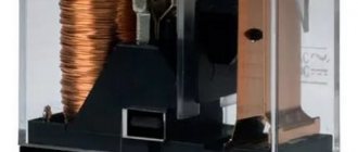
Relay for monitoring the health of lamps VAZ 2114
How the device works
As you can easily guess from its name, the VAZ 2114 lamp health monitoring relay is designed to check the current state of automobile lamps (namely, side lights and brake lights), as well as to notify the driver in case of their failure. So, if even one of the indicated lamps fails or if the section of the on-board network responsible for their operation is broken, the corresponding icon will light up on the instrument panel.
Location of the lamp health monitoring relay
The location of this relay is the common (in other words, mounting) block located inside the engine compartment. It serves to house all car fuses, as well as a number of relays responsible for the correct operation of the internal network. The relay we are interested in has an oblong shape and is designated by the index K4.
It is included in the electrical circuit according to the following principle:
The relay for monitoring the health of VAZ 2114 lamps, the diagram of which is presented above, functions as follows:
- if the resistances in sections ACD and ABD are the same, then the potential difference between point C and point B is zero;
- if the resistance in one of the sections changes due to a lamp burnout, then a potential appears between the indicated points, causing the warning light on the instrument panel to operate;
- if a break occurs in one of the sections of the circuit, then potential also appears between points C and B, and the warning light in the cabin goes off.
This operating principle is called a resistor bridge. It allows you to almost accurately determine the presence of a malfunction in the lamp power supply circuit (in order to avoid accidental operations during small network fluctuations, the relay is designed for potential differences that are as close as possible to the difference formed during a break).
As you can see from this, the activation of the relay and the glow of the signal icon on the panel can be not only signs of a burnt-out light bulb or brake lights, but also signs of a violation of the integrity of their electrical circuit.
Explanation of the additional fuse and relay block
To turn on the main systems of any car, the manufacturer has designed the installation of auxiliary fuses. As a rule, they are located in the center console area. Each auxiliary module consists of several important relays and fuses.
In this particular case, the box is located to the left of the glove compartment, behind the side trim of the center console. To quickly access the box, you need to remove part of the plastic protection. The protection is attached to Phillips bolts, so you need to prepare the appropriate screwdriver.
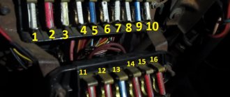
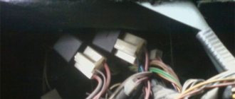
Location of additional fuse and relay box 2114, 2115, 2113
Additional unit in the cabin Diagram of the additional unit
Table 3. Explanation of the additional fuse and relay block
| № | Current, A | Purpose (Fuses) |
| 1 | 15 | Main distribution relay |
| 2 | 15 | Controller power |
| 3 | 15 | Fuel pump |
| № | Purpose (Relay) | |
| K4 | Fuel pump | |
| K5 | Cooling fan | |
| K6 | Main system control relay |
There are also options for other decryptions.
Explanation of the additional fuse and relay block
Relay:
Fuse:
f2 - main relay;
f3 - ECU (electronic control unit).
Relays that control the supply of current are present in the design of many vehicles. They are designed to perform a very important function - they turn on and off important electrical devices and mechanical systems of the vehicle. In simple terms, this is a device for supplying current to a required element.
The lamp control relay has tripped - what is the reason?
There may be several reasons for the activation of the K4 VAZ 2114 relay, namely:
- one of the stop or clearance lamps has burned out;
- there was a break in the wiring;
- the relay has failed;
- a false positive occurred.
You should, of course, start troubleshooting with incandescent lamps - to do this, just check them for functionality and, if a burnt-out one is identified, replace it with a new one. After this, the resistance in the resistor bridge of the relay circuit will return to normal and the control signal will go out.
The light on the lamp health monitoring relay is on
If it turns out that the light bulbs are fully operational, then you should check the condition of their power circuit. This can be done with a regular test with a multimeter. Sections of wires found with breaks should be replaced with intact wires.
It should be noted that for a relay, the lack of power to the lamp due to a broken wire is similar to the burnout of the lamp itself. For this reason, you should always check the on-board wiring and not rush to replace the relay with a new one.
If the lamp power supply circuit turns out to be working properly, then the problem probably lies in the device itself. Sometimes, during prolonged use, the relay becomes sour and remains in the permanently closed position. To check its serviceability, the easiest way is to replace the relay with another one, exactly the same. If the problem disappears, then the cause has been found.
Lamp fault monitoring relay terminals
Limitations and procedure for modifying the turn relay
Installation of LEDs is possible only if the relays are digital. For cars of the VAZ or GAZ family, these are devices marked with the designation 494.3747 (for comparison: the designation for analog ones is 231.3747). When there is no marking, the relay class is quite simply determined by its dimensions, which are noticeably larger for the analog version. If the car only operates analog, you will have to purchase a digital one.
Appearance of digital and analog turn relays
The direction indicator is modified in the following sequence:
- The case is opened;
- The location of the chip responsible for the operation of the turn signals is determined: it is usually located to the right of the external board.
- The capacitor is replaced, which determines the frequency of the turn signal lamp blinking generator. The subtlety is that the capacitor capacity should be within 4.7 µF at 50 V operating voltage. Alternatively, you can install another capacitor; in most cases, the space inside the relay case allows this operation.
- Output parameters are monitored using measuring instruments. If the LEDs are functioning properly, the housing is installed in its original place.
As additional items you should purchase:
- P-channel transistor;
- A resistor from the above resistance range (if it will be soldered into the circuit and not a capacitor);
- LEDs (preferably red or orange).
Soldering of such a modernized version of the relay can be done using the usual hinged method, on top of the main circuit.
Typical malfunctions of VAZ car lamps and their elimination
One of the most common problems is filament burnout. In this case, the electrical circuit is open, and the fuse sends a corresponding signal to the relay, which in turn outputs it to the dashboard. To fix this problem, you need to replace the light bulb.
The second problem is a violation of the electrical circuit itself. There may be several reasons for this.
- The contacts of the wires are broken (they have oxidized) leading to the fuses or relays. To eliminate this damage, you need to disconnect them and clean them well.
For other, more serious problems, it is better to contact specialists who must conduct a serious diagnosis of the operation of the relay to control the car's lamps in order to avoid a strong short circuit in the car's electrical circuit and its subsequent fire
It is especially necessary to pay attention to the poor performance of devices after tuning a car, since in most cases the load on the network increases due to the addition of additional energy-consuming lighting equipment (diodes, more powerful high-beam lamps)
The relay, which is responsible for monitoring the serviceability of lamps in VAZ cars, is located in the mounting block in the engine compartment. It has its own markings and designations, and is responsible for informing the driver about the presence of malfunctions in the car’s lamps.
Relay upgrade
In addition to the above cases, false positives sometimes occur. They are typical for cars whose electrical network has been tuned. In the vast majority of cases, they appear if conventional parking and brake light lamps have been replaced with LED ones, which has led to an imbalance of the resistor bridge arms.
In order to eliminate such a malfunction, you will need: 2.2 Ohm resistors with a power of at least 3 W, a knife or a sharp, durable blade and a soldering iron.
The procedure itself must be performed in the following order:
- Remove the relay from the common block.
- Open it with a knife, then remove the lower part from the body.
- Remove two electrical circuits from the bottom plastic part (later you will need a circuit with 4 spiral resistance wires).
- Unsolder the wire resistors to be replaced (only those resistors need to be replaced, the lamps in the circuit of which have been replaced with LED ones. For the front dimensions, these are spirals located between legs 7-8 and 10-11 of the relay; for rear dimensions, these are spirals between legs 1-7 and 9-10).
- Solder instead of the removed resistors new ones with a resistance of 2.2 Ohms.
- Insert the electrical circuits into the bottom of the housing and assemble the relay.
- Install the relay in its place inside the common block.
Repair of lamp service relay
After such a simple replacement, the lamp control relay will work correctly even with LEDs installed.
In conclusion, I would like to say about another sometimes encountered problem, namely, the absence of a control relay in the car, instead of which jumpers are installed directly from the factory. You can fix this problem yourself - you just need to buy relay 97.377 at a car dealership and, after removing the jumpers, install it in place. After this, the lamp status monitoring system will begin to function as usual.
Location of the VAZ 2114 starter relay
Starter protection is designed to protect the circuit of the corresponding unit from overload or short circuit. In appearance, it is a standard four-pin device suspended on a bolt inside the engine compartment.
In this case, the injector or carburetor is designed in the same way - the block is suspended independently. The exact location of the element is impossible to describe. Thanks to the “special” approach of the designers, the hitch may differ depending on the year of manufacture. Therefore, it is best to start your search from the starter terminals and move along the wires to the device itself.
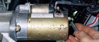
Locating the starter relay
The starter retractor is an electromechanical device installed directly inside the unit housing. The part is responsible for the clutch of the engine flywheel with the electric motor gear.
The search is carried out by visual inspection. The retractor is located in the same housing as the main unit and has two large contacts coming from the ignition switch and the battery.
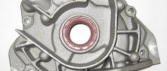
Retractor design
The VAZ 2114 starter solenoid relay is located on the housing of the starting electric motor and is securely fastened to it. The device consists of separate windings and a contact group.
Mechanism of action
Operating principle of the device:
- when turning the ignition key, power is supplied to the retractor winding;
- the working plate, under the influence of current, is pressed against the contacts;
- power is supplied to the starter;
- the engine turns over and the engine starts.
Signs of malfunction of the retractor relay on the VAZ 2114
There are a number of symptoms that indicate a device failure. The symptoms are specific to this part and are difficult to confuse with other problems.
Typically, masters highlight:
- nothing happens after turning the ignition key;
- the starter fires, but does not turn off, which is accompanied by a characteristic sound.
No clicking of the solenoid relay
If there is no characteristic sound of the solenoid relay operating, the problem should be looked for further:
- the contacts of the working plate have oxidized;
- there is damage to the ground cable;
- The solenoid coil of the relay is burnt out.
There is a click, but the starter does not turn
If after turning the key there is a characteristic sound, but then nothing happens, the components are checked.
- Charging the battery. If there is no voltage on the windings, clicks may appear, but the current will not be enough to start the motor.
- Damage or wear to the commutator.
- Oxidation of the retractor element.
The relay is activated, the starter starts the engine, but does not turn off
The most common cause is a clogged starter armature. In this case, the bendix wedges and its working part does not disengage. In second place is a breakdown of the ignition cylinder - the key release may not work, or the contact group does not move easily enough.
Instructions for replacing the relay on a VAZ-2114
Replacing the starter solenoid relay, as well as the engine itself, is a responsible process that requires close attention and extreme care.
Starter relay installation diagram
The electrical circuit for connecting the starter relay is not complicated. Any car enthusiast can carry out installation work, provided he has sufficient experience and a minimum set of tools.
How to replace the starter relay
To replace a unit, you must follow a sequence of steps.
- Securely lock the machine in place.
- Remove the terminals from the battery.
- You will need to disconnect the red wire from the relay.
- Using an open-end wrench No. 8, unscrew the screw of the brush assembly and remove the wire connected to it.
- Loosen and remove the tie rods securing the device to the ground.
- Dismantle the power cable and remove the device.
- Assembly is carried out in reverse order.
Checking work
The most reliable way to check is the “scientific poke” method. After assembling the device, you will need to start the engine. If the procedure was successful, the module operates normally.
Starter Interlock Relay Location
The starter interlock device is a separate unit that prevents the rotation of the electric motor armature after starting the power unit of the machine. Thanks to a well-thought-out design, after turning the ignition key, a group of contacts is closed, passing current to the starter. After the motor spins up and the circuit opens, the diode closes and the excited windings are de-energized.
The exact location of the block differs depending on the year of manufacture. The type of power plant also affects the installation.
How to diagnose resistance?
To diagnose a fuse failure by resistance, it is necessary to dismantle the element and switch the multimeter to resistance measurement mode. After this, you need to connect the leads of the tester and the fuse. If the device screen shows a zero value, it means that the worn element needs to be replaced.
In cases where there is no spare fuse at hand, you can “patch up” the circuit using ordinary wire. However, keep in mind that this repair option is permissible only in extreme cases and you need to put the unit in order as quickly as possible by installing a new working element in place of the broken element. Otherwise, you risk not only not solving the problem, but also making it worse.