Operating principle
Essentially, a relay is an electromagnet. When control voltage is applied to the coil, the rod attracts the armature, thus switching the circuit.
There are three types of relays:
with normally closed contacts;- with normally open;
- throwing over.
When a control signal is applied to a device with normally closed connectors, they open; if there is no signal, they close. For relays with open connectors, the opposite is true. There is voltage on the winding, the terminals close, but when there is no voltage, it opens.
In flip-over models there are two sets of connectors, one normally closed and the other normally open. They have a common terminal. When current is applied to the winding, the contacts switch from one position to another.
Switching device design
An electrical relay is a device designed to be used as a switch. It can connect or disconnect an electrical circuit depending on the control signal coming to it. The line that is connected to the element is called controlled, and the one through which the command is sent to it is called control.
Relays are used to automate various operations. They successfully cope with managing various kinds of signals and protecting electrical equipment. They are used in security and heating systems, sound engineering, that is, wherever automatic switching of operating modes is necessary when any parameters change.
When searching and eliminating various faults in equipment, one of the repair stages is to test the switching element. This is done using a quantity meter. But before you test the relay for functionality with a multimeter, you should know how it works and understand the principle of its operation.
Principle of operation
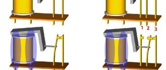
A relay is an electromagnet consisting of a contact group, an armature and an inductor. All parts are installed on the base and placed in a closed housing. The elements are mounted as follows: an anchor (yoke) is placed on top of the core of the magnetic system. It is held in its initial position by a spring and is a movable L-shaped plate.
A group of plates with contacts is attached to the lower arm of the transmission, and the same number of contact bases is installed opposite them. Each lamella contact extends outward from the housing, forming the terminals of the device.
The principle of operation of an electronic device is the ability of an electromagnetic field to influence conductive objects. When voltage is applied to the terminals of the winding, current begins to flow through it. When its value reaches a certain value, two forces (electromotive and magnetic) arise in the winding, forcing the armature to press against the surface of the coil, overcoming the force of the spring.
Depending on the design, the initial position can be either closed or open, so in the second type of relay, after applying voltage, the line will open. As soon as the signal of the required amplitude is removed from the terminals of the relay winding, the contacts of the device will return to their original state.
Types and characteristics
Electrical relay elements differ in the number of pins and shape, but their essence remains the same - connecting or disconnecting the load from the signal line. According to the type of physical processes that lead to recommutation, relays are divided into the following types:
- neutral - do not depend on the polarity of the signal supplied to the control terminals;
- polarized - in them the position of the contacts depends on the direction of the current;
- magnetoelectric - react only to direct current;
- ferrodynamic - their design uses ferromagnetic cores that enhance the magnetic flux;
- induction - based on the connection between a changing magnetic flux and an induced current in a conductor;
- thermal - react to heat that appears when current passes through the plates and changes their shape;
- electronic - they use the property of a pn junction to conduct current in only one direction (diode).
Devices are also divided according to the type of contacts, which can be of three types: normally closed, normally open and changeover. Like any electromechanical device, a relay is characterized by its technical parameters that determine the operation and purpose of the device. Of course, it will be impossible to check all the parameters of the relay with a multimeter, but with its help you can accurately determine the functionality of the switch. The main characteristics of the device include:
- winding voltage is the value of the signal amplitude at which the relay switches from one stable state of contact connection to another;
- switching current denotes the highest value of current that the relay can pass through without changing its parameters;
- the rated voltage is divided into values corresponding to alternating and constant signal levels, indicating the maximum potential difference, the appearance of which is permissible at the terminals connected to the load;
- operating frequency is the number of switchings that a device can perform per unit of time;
- wear resistance is determined by the mechanical reliability of contact groups, measured in cycles;
- The response time is characterized by the interval during which the position of the contact groups changes after the arrival of the control signal.
Functionality check
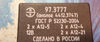
On the body of each relay there is a diagram with contact numbers and control voltage rating. A rectangle with pins 85 and 86 means a coil. Therefore, when measuring winding parameters, you need to connect to them. Other pins numbered 30, 87 and 87a (88) are the switching key for the external circuit.
It is convenient to use a digital multimeter as a tester for regulator relays and any other electromagnetic relay. This is because it can measure current, voltage and resistance.
Since the performance of the device depends primarily on the health of the winding, the test begins with measuring the coil resistance. Its values range from several tens of ohms to several hundred ohms.
To do this, switch the multimeter to resistance measurement mode. We connect measuring probes to pins 85, 86 and take readings. If the resistance is within normal limits, then you need to check the condition of the controlled outputs.
In a relay with normally closed contacts 30 and 87, when measuring the resistance between them, the multimeter should show 0 Ohm. With normally open pins 30 and 87 the resistance between them should be infinity. When the control voltage is applied to the coil terminals 85 and 86, everything should change exactly the opposite.
Sometimes only the actuation current is known, then the coil resistance is measured. After this, the multimeter readings are multiplied by the operating current, and the control action of the winding is obtained. Then, by applying the calculated voltage, you can check the contact group, as described above.
Only AC voltage can be applied to the AC relay coil.
After checking the relay, if there is a need and the ability to adjust the contacts, do so. Otherwise, replace the entire device. Its installation and removal must be carried out with the device's power turned off.
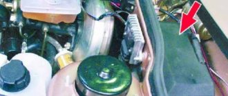
How to check the generator relay with a multimeter without removing it from the car?
Signs of regulator failure are clearly visible. Especially if the temperature outside is sub-zero. The battery will always be either undercharged or overcharged. In the first case, a weak battery charge can be easily determined by how the starter turns the engine. He will barely twist it, and to no avail. Sometimes when you turn the key, nothing happens at all, and the lights on the panel go out.
Recharging the battery is practically no different. The same thing will happen, plus the electrolyte from the battery cans will boil away. Overcharge can be determined by the decrease in electrolyte in the banks. As a result of evaporation, a white coating may also form on top of the battery. Parts of the body under the battery may also have a white coating. Usually, with such symptoms, drivers think that the battery is damaged, but in fact there is nothing wrong with it, but the problem is in the relay-regulator, and that is what you need to pay attention to first. But to do this, you must know how to test a relay with a multimeter.
This is not difficult to do. To do this, take our multimeter and set it to voltmeter mode. With its help, we can measure the voltage when the motor is turned on. Note that when the engine is turned off, the normal voltage should be in the range of 12.4-12.7 V. If, for example, the voltage is 12 V, then the battery needs to be charged and the reasons for the undercharging should be looked for.
Application in car
Most often motorists have to deal with switching devices. We are talking about the generator (starter) regulator relay. They remember it when the engine stops starting and it turns out that the battery is discharged. One of the reasons for this is a malfunction of the regulator.
On older cars, to maintain a constant voltage, a regulator was used, consisting of three devices - a voltage stabilizer, a current limiter and a reverse current relay. The regulator prevents the battery from overcharging, which prolongs its service life.
It can be built into the starter brush block or performed as a separate module. Its failure may or may not overcharge the battery. In the first case, streaks will be visible on the case, the electrolyte will begin to boil away, which will lead to a voltage drop below 12 volts. In the second, the values will initially be lower than acceptable. As a result, the engine will not start.
Abnormal values on the multimeter
If the values deviate from those indicated upward or downward, this indicates a malfunction of the relay. For example, if as the engine speed increases the voltage drops to 12 V, then something is clearly wrong. Also, an increase in voltage to 15-16 V indicates a malfunction of the relay regulator.
Voltage surges do not always indicate a faulty relay, but very often. Sometimes the generator itself can fail. In any case, when voltage surges occur, you should first change the regulator, and if the problem persists, then you need to replace the generator and completely check the system.
Checking the starter regulator
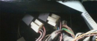
To check the starter regulator relay without removing it from the car, you can use a multimeter and test all the wires that go to it. To do this, they are first disconnected from the regulator. The multimeter is switched to resistance measurement mode, the disconnected wires are checked.
If everything is normal, then the conductors are returned to their place. The voltage at the battery terminals is measured with the engine off. The multimeter is switched to DC voltage measurement mode in the range from 0 to 20 Volts. The probes attach to the battery terminals. The device should show 12.2-12.7 V.
If 12 volts or lower, then it needs to be recharged.
Then the engine must be started and checked again with the same measurements. If the voltage is in the range of 13.2-14 V, then this is normal. We add engine speed to 2000 per minute and measure again. Normally, the multimeter should show between 13.6-14.2 V. We also add revolutions to 3500 per minute.
We take readings. They should not exceed 14.5 Volts. If the value does not change and remains 12.7 Volts, as when the engine is turned off, or even decreases, then the regulator relay is faulty. Therefore it needs to be replaced. If 14.5 Volts are exceeded, the regulator must also be changed.
Sometimes the question arises of how to test a relay with a multimeter if there is no access to the regulator. Then you need to remove it, and to check it you must have, in addition to the tester, a charger with a voltage regulator and a light bulb.
The following scheme is assembled from them. The charger is connected to the input terminals of the regulator, and the light bulb is connected to the output (thick) terminals. A multimeter monitors the voltage at the regulator input. By charging we change the voltage from 12 to 15 volts. The light should go out at 14.5 volts. If this does not happen, the regulator is faulty and must be replaced.
Definition
Before you test a relay with a multimeter, you need to understand what a relay is. This is a device designed to regulate the current of a car's alternator, preventing it from overcharging the battery. Therefore, because of this element, batteries last longer.
By and large, a relay is a voltage stabilizer that does not allow voltage greater than 14.5 Volts. This device is extremely accurate and is a must for all types of machines. However, there are several types of relays.
Checking the solenoid relay
When the battery is charged, but the engine does not start, you need to check the starter.
If the generator spins but the engine does not, then in such cases it is necessary to check the solenoid relay of the electric motor and the bendix. To do this, you need to remove the starter. After this, all contacts are cleaned, and the resistance of the relay winding is measured with a multimeter.
If the value is infinity, then the winding has burned out. In this case, it is necessary to rewind the coil or replace it. The device shows several tens of ohms, which means the winding is intact.
Then its performance is checked. The positive terminal of the battery is connected to the corresponding relay terminal using the cigarette lighter. And the minus is connected to the starter housing. A click should be heard, then the device is working properly, otherwise it needs to be disassembled and the mechanical part checked.
Types
To broadly generalize, there are only two types, and they work on the same principle - they increase or decrease the voltage to the required value - 14.5 Volts. The first type is a relay combined with a brush assembly. It is usually attached to the generator itself, and the relay itself is located in the housing where the brushes are placed.
The relay can also be made as a separate device that is mounted on the car body, and the wires from it go to the generator, and then to the battery.
The housings of both types of relays are filled with glue or sealant, and they cannot be repaired at all. This means that if we check the solenoid relay with a multimeter and it turns out that it is not working, then we are guaranteed to have to buy a new one. Fortunately, it is cheap, especially for domestic VAZ cars. Therefore, it is more convenient and easier to buy a new relay rather than hacking away at the old one.
If it “dies”, then the battery will be recharged. This means it's time to change the relay. But for this it is important to know how to test a relay with a multimeter, because we need to find out that the problem is in it, and not in any other part of the generator. There are at least two options for checking: without removing it from the car and with removal.