If the task is to check the electrical circuit for breaks (leaks), then you need to familiarize yourself with how to test the wires with a multimeter. A specialized measuring device is indispensable when testing wiring. And even if you are not a professional electrician, once you understand the basic rules for safe use of a multimeter, you can easily identify problem areas in your home electrical network.
In what cases is wire testing carried out?
This question can be answered in a few words - if the current-carrying core breaks or the integrity of its insulation is compromised.
Let’s clarify this answer and consider typical situations:
- Let's say an outlet or switch stops working. After you have made sure that the problem is not in the connections (including the junction box) and not in the light bulb (lamp), it is advisable to ring the wires in this area. If the integrity of the wiring is compromised, the multimeter will signal this.
- Developing the first example, it can be noted that such situations are not uncommon during repair work (drilling holes) and short circuits due to dilapidated wiring and network overloads.
- An atypical, but quite effective use of multimeter testing is to determine the required conductors on large sections of wiring. This method is appropriate when the color marking of the wires does not allow you to accurately identify the desired conductor.
- Also, in everyday life, dialing allows you to determine the integrity of electrical appliances (lamp, iron, switch, fuse). And if you are well versed in electronics, then when soldering, repairing printed circuit boards and other devices, testing circuits is a mandatory step.
Homemade contactless dialing
Below is a diagram of a simple non-contact break detector; it can be assembled within one evening. Considering the small number of parts, you don’t have to bother making a printed circuit board, but use wall mounting.
Detector circuit
List of required radio components:
- variable resistance R1 – 100 kOhm;
- resistor R2 – from 4 to 8 MOhm;
- electrolytic type capacitors: C1 and C3 – 220 µF, C2 – 33 µF;
- ceramic capacitor with a capacity of 0.1 μF;
- D1 – LAG 665 chip (preferably in a DIP package);
- SP is a regular earphone from a telephone headset.
The circuit can be powered from a source with a voltage of 2 to 5 volts.
The dipstick (P) is made on the basis of a regular spoke from a bicycle wheel.
Probe for a homemade break detector
Properly assembled contactless cable testing does not require adjustment.
Video: Do-it-yourself cable testing. How to test wires using a light bulb and battery
If you calculate the cost of all the necessary parts, it is easy to see that the result obtained will be an order of magnitude less than the cost of services for detecting a broken wire, indicated in construction estimates.
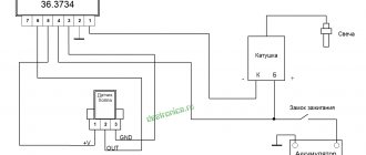
The electrical network (wiring) of modern cars is single-wire, the second conductor is “ground” - the car body and the engine. During the operation of the vehicle, you may encounter some wiring faults (for example, a short circuit or break). Next, let's look at the instructions on how to find them yourself.
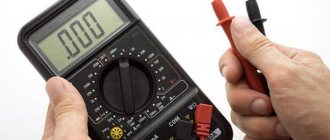
Multimeter for testing wires
What do you need to know about this device? Firstly, it is worth noting the price variety and availability. Even inexpensive multimeters can flawlessly cope with many tasks, including testing wires.
Let's take a closer look at a typical budget option. Let's get acquainted with the design, layout and determine its functionality.
As you can see, a typical device has a digital display, controls and sockets for connecting probes. Let's decipher the main modes of the multimeter:
- OFF – the device is turned off (some devices have a special button for this).
- ACV (may be designated V~) – measurement of alternating voltage.
- DCV (can be designated V...) – DC voltage measurement.
- ACA (may be designated A~) – measurement of alternating current.
- DCA (may be designated A...) – direct current measurement.
- Ω - resistance measurement.
- hFE – measurement of transistor parameters.
- ->Ι- – conductivity check (circuit continuity).
The sockets for connecting probes are marked as follows:
- COM(-) – common socket for connecting the black wire.
- VΩmA(+) – socket for connecting the red wire.
- 10A...MAX – socket for connecting the red wire when measuring direct current, the maximum value of which does not exceed 10 Amperes.
Within the framework of the issue under consideration, only two modes of the multimeter will be considered:
| Resistance measurement mode. |
| Conductivity test (continuity) mode. |
| Availability of sound when checking conductivity. |
The presence of sound, which is not mandatory, complements the dialing mode and simplifies the verification process. You do not need to constantly be distracted and look at the device display. The presence or absence of a buzzer signal will give a clear indication of the integrity of the conductor being measured.
Calling the wiring
Dialing tools
Multimeter for dialing
Most often, testing is done with a multimeter - a special device designed to record various parameters of an electrical connection (current, voltage, resistance, etc.).
A simple multimeter is inexpensive and therefore deserves a permanent place in your toolbox.
A multimeter set to dial mode (most often indicated by the corresponding icon) will help you if necessary:
- Check contact availability
- Check the integrity of the electrical circuit
- Check the operation of the switch or socket
- Figure out which of the cable bundles (a very common situation in our apartments) is connected where.
Multimeters can be digital or analog, but the principle of their operation remains the same.
We will tell you how to use a multimeter to test wiring in the next section.
Testing with a multimeter
When testing the wiring using a multimeter, we perform the following operations:
We set the dialing mode on the multimeter - most often it is marked with an LED.
- Then we move on to the place where the wiring rings - the junction box. There, as a rule, we are presented with a bundle of unmarked wires.
- We find the phase - after turning on the machine, we check all the wires using an indicator screwdriver. We mark the found wire using insulating tape or window tape.
- Next we look for zero. We turn on the multimeter to measure voltage (if we need to find 220V, we set it higher - for some models it is 600 V). Then we touch the phase with one multimeter probe, and with the other we test the wires one by one. As soon as the required 220V appears on the multimeter, the wire we need has been found. We mark it too.
- We check other pairs of wires using the same principle, and mark them in the same way.
Using a multimeter, you can not only test the wiring in the junction box, but also check whether there is a break in the wire (for example, in the power cable).
Conductor integrity check
We check the integrity of the conductor as follows:
- Disconnect the conductor from the current sources. If the conductor is a multi-core cable, then we do this for all the wires included in it.
- We turn on the multimeter either in the continuity mode, or in the resistance measurement mode at the roughest limit.
- We connect the probes of the multimeter: zeros should appear on the display, and in the ringing mode with sound accompaniment, the device will make a squeak.
- We connect the open probes of the multimeter to the conductor. An entire conductor shows zero resistance.
- For a multi-core cable, the verification procedure is the same, but you must first mark the corresponding cores (if they do not differ in the color of the insulation).
If, after checking, no violations of the cable integrity are detected, then the fault should be looked for elsewhere.
Testing the wires in the apartment, searching for a cable break or a short circuit can easily be done independently. And yet, we remind you once again - even if you are an experienced electrician, do not forget about the safety rules!
The principle of testing and determining resistance
If you carefully examine the multimeter, you will notice that the continuity mode (diode testing) is in the resistance measurement zone. In simple words, continuity testing combines the determination of conductor resistance, analysis of the data obtained and output of the result with an additional sound signal.
To understand the principle of dialing, it is enough to first know Ohm's law. It states: “the strength of the current in a conductor is directly proportional to the voltage at its ends (potential difference) and inversely proportional to the resistance of this conductor.” Based on this rule, resistance R = U ⁄ I, where I is the current strength, U is the network voltage.
Knowing how resistance is determined, it remains to understand where the current and voltage come from during measurements (for safety reasons, the circuit being tested must first be de-energized). It's simple. The multimeter has a power source that creates voltage and supplies current. By comparing the initial data with the amount of loss caused by connecting to the measured resistor, wire or light bulb, the final result is calculated (unit of measurement - Ohm).
Conclusions and recommendations
- We always carry out resistance measurements in the free state of the tested conductors. Measuring a live wire is lethal. At least for a multimeter.
- Measuring a circuit is actually testing its electrical resistance.
- When the conductor is not damaged, the measurement result should be no more than a few ohms.
- Before performing the break measurement itself, it is worth performing a test measurement on the probes to check whether the device is working.
Checking for broken wiring in a car is done in the same way, with the only difference being that you don’t have to worry about a 220 V current shock due to the absence of one (this does not apply to electric cars - there are even 600 V there!).
Safe and correct operation of the multimeter
Working with electrical devices and networks must be safe. This rule also applies to the procedure for ringing conductors with a multimeter. Let us highlight the main recommendations that must be followed before and during work:
- First of all, the circuit must be completely de-energized by turning off the machine in the switchboard and removing the batteries (if the object in question is an electronic device).
- The capacitors in the circuit must be discharged by short-circuiting. Otherwise, during measuring work, the multimeter may fail.
- For convenience when making measurements, it is recommended to use special tips (“crocodiles”) at the ends of the measuring wires. These devices create reliable contact with the conductor being tested and, at the same time, free your hands.
- When trying to fix the probe, it is not recommended to touch the bare wires and the tip of the probe with your fingers. Otherwise, the results obtained may be incorrect.
We check the wiring in the apartment with a multimeter
Let's take as an example a modern apartment in which the wiring is done in accordance with current requirements and standards. This means that when laying the lighting lines and power outlets, they were separated, and separate wires were laid for them in each of the rooms. Each of these circuits is powered from the apartment panel through a separate circuit breaker.
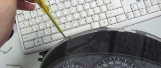
If the light has gone out in one of the rooms, you should first check that the lamp is working properly. Before starting work, it is necessary to turn off the power to the room/apartment depending on the power supply. When using an opaque incandescent lamp in a lamp, the integrity of the filament is difficult to visually determine, so you will need a multimeter and its continuity function. Let's figure out step by step how to do this correctly.
How to ring wires using a specific example
As an example, consider a standard wiring network in an apartment or private house. Ideally, all electrical communications should be made in accordance with the standards, all consumers are separated (grouped) and each circuit is powered in the distribution board through a specific machine.
Condition: the socket in one of the rooms stopped working. Task: identify the cause of the malfunction. Solution:
| The first step is to check the switchboard for automatic operation. If all the machines are in the on position, then it is necessary to de-energize the line under test (or the entire apartment). | |
| Now, to eliminate the banal version of a malfunction of the socket itself, it needs to be removed from the socket box and visually inspected for defects and poor contact. Conventional sockets have a simple design. For more expensive models that have terminal blocks as clamps, it is better to ring them additionally. | |
| After making sure that the outlet is working, you need to check the connection of the wires in the junction box. If there are several distribution boxes in the room, then the one you need will be located above the faulty outlet or in close proximity. | |
| In the distribution box, the main cable is broken, connected to the socket wires and then goes to the next consumer (distribution box). | |
| As can be seen from the example, there are three twists in the distribution box (phase, neutral, ground). When testing, the tip of one probe should touch the exposed twist. The second probe checks the socket contacts one by one. Or, if convenient, one probe is fixed in the socket contact, and the second one alternately checks the twists in the junction box. |
Having considered the main sequence of actions, we note important points and features during measurements:
- At the stage of checking the twists in the junction box, if there are no visible defects, you can additionally check the live connections. To do this, apply current by turning on the circuit breakers in the switchboard. If there are doubts about the color marking of the wires, the phase can be determined using an indicator screwdriver (when it comes into contact with a phase conductor, the indicator in the screwdriver lights up or a sound signal sounds). To find working and protective grounding, you will need a multimeter. After the phase conductor (L) is found, the ACV mode is set on the multimeter (can be indicated as V~ alternating voltage measurement) at a level above 220 V, the red phase probe is fixed on the phase conductor, and zero and ground are determined with the black probe. When in contact with the working ground (N), the device will display a voltage within 220 Volts. When the probe touches the protective ground (PE), the readings will be below 220 Volts. After checking, the apartment (room) should again be de-energized.
- Next point. It is not always possible to be absolutely sure that the wires from the outlet being studied go to the nearest junction box. It happens that sockets, bypassing distribution boxes, are powered with nearby sockets. A connection is also common, when two sockets in adjacent rooms are mounted at one point on a common wall. All this needs to be analyzed and taken into account.
- The issue of convenience of measurements is very relevant. After all, as a rule, the socket and the distribution box are located at a considerable distance, and the measuring probes of the multimeter often have a length of 30 - 50 cm. In this case, for convenience, you can insert a jumper into the socket (connect two contacts), and perform the test directly in the distribution box box. A more accurate measurement can be made by connecting the outlet to a working extension cord.
Testing multi-core cables for the purpose of marking them
When marking multi-core cables, you can use the methods described above, but there are ways to significantly simplify this process.
Method 1 : use of special transformers that have several secondary winding taps. The connection diagram for such a device is shown in the figure.
Using a transformer for marking
As can be seen from the figure, the primary winding of such a transformer is connected to the power supply network, one end of the secondary winding is connected to the protective shield of the cable, and the remaining terminals are connected to its conductors. To mark the wires, it is necessary to measure the voltage between the screen and each wire.
Method 2 : Use a block of resistors with different values connected to the cable wires on one side, as shown in the figure.
Resistors connected to cable terminals
To identify the cable, it is enough to measure the resistance between it and the screen. If you want to make such a device with your own hands, then you should select resistors in increments of at least 1 kOhm to reduce the influence of wire resistance. Also, do not forget that the value of the resistors has a certain error, so first measure them with an ohmmeter.
When checking a multi-core telephone cable, installers often use a dialing headset, for example TMG 1. Actually, these are two telephone handsets, one of which is connected to a 4.5 V battery. Such a simple device allows you not only to check the cable, but also to coordinate your actions during installation and testing.
Calling with a telephone handset
Setting up a multimeter before dialing
Dialing mode
Before starting measurements, the switch on the multimeter must be set to dialing mode (->Ι- and buzzer icon).
The ends of the test leads with probes must be installed in the appropriate sockets. The black wire goes to the COM socket, and the red wire goes to the VΩmA socket. This combination will allow you to maintain polarity when taking measurements, but in the case of checking the integrity of the wires, continuity will not play any role.
Next, to make sure that the multimeter is working properly, the black and red probes must be connected to each other. In this case, a signal should sound (if there is a buzzer), and a value close to or equal to zero will appear on the screen.
Checking the electrical wiring
Check at the installation stage
First, let's look at the potential problems that an electrician can expect when installing new wiring. As a rule, such wiring is laid along bare walls (or in specially made grooves), and then covered with plaster and finishing.
The first check of all electrical wiring must be carried out before starting any plastering work!
Otherwise, an unpleasant surprise may await you in the future: to troubleshoot problems with the wires, you will have to open the plaster.
At this stage, possible sources of problems with electrical wiring can be divided into two groups:
- Errors of builders (plasterers, concrete workers, finishers)
- Electrician errors
And if the first group can be dealt with only by vigilant supervision, then electrician errors can be avoided by carefully following the drawn wiring diagram when laying it and carefully checking it before starting finishing work.
New wiring that needs checking
Easy testing of new electrical wiring
So, we have come to the point where the wiring is laid. And it seems to be laid out correctly.
What can we do at this stage to make sure the wiring is working properly?
- We check the wiring for a short circuit: there should be no contact between zero, phase and ground . The quality of wire insulation at high voltage directly depends on the quality of the cable, so if you didn’t skimp and didn’t buy the cheapest option, then, as a rule, there are no problems here
Multimeter readings when dialing
When checking the integrity of the wire, first of all you need to make sure that its ends are cleared of insulation. By touching the multimeter probes to the bare ends, you will get a certain result:
- The wire is intact . In this case, a signal will sound, and the device reading will be equal to zero ( 0 ) or the value of the conductor resistance (it should tend to zero, for example 0.01).
- The wire is damaged . This is indicated by a unit ( 1 ) displayed on the screen and the absence of a buzzer signal. A unit indicates that the resistance level between the probes is higher than the measurement limit.
Cable testers
This class of devices allows you to check both the integrity of the cable and the correctness of its connection, which is very important for Internet provider networks. These can be simple devices that check crossover or complex devices on a PIC controller that have an ADC and a built-in multiplexer.
Multipurpose cable tester Pro'sKit MT-7051N on a microcontroller
Naturally, the cost of such devices does not encourage their household use.
How to check wire continuity in resistance detection mode
In multimeters that do not have a continuity function, checking the integrity of the wire can be done in the resistance measurement mode.
Determining resistance with a multimeter
In this case, the probes are connected in the same way as during dialing, and the device is set to resistance determination mode ( Ω ).
You need to start measuring at the very minimum threshold of the instrument scale - for example, 200 Ohms. All actions are the same as when calling. You just need to monitor the readings of the device. If the wire is intact, the display will show its resistance value. If there is a break, then the resistance will not be displayed (OL - overload condition).
Safety requirements
When performing any inspections of live electrical networks, safety requirements must be followed. You cannot work without protective insulated shoes, and it is also better to wear rubber gloves. When checking the integrity and insulation resistance of electrical circuits, it is necessary to de-energize the network by turning off the circuit breakers, so all checks should be carried out during daylight hours, since with emergency lighting and the light of lanterns you can only work in case of an emergency.
Originally posted 2018-07-04 07:39:48.
Specifics of dialing of some devices
You can use a multimeter not only for cable measurements. Experts use it to measure electrical equipment.
Fuse
Checking the fuse by resistance
Devices in the form of a small box with a thin internal cable prevent overheating and fire of circuit elements. Models without wiring are tested as follows:
- The device is switched to dialing mode.
- The probes are applied to both sides of the fuse.
- When the resistance is 0 Ohm and there is sound, the device works.
- The number 1 appears, there is no sound - the fuse is broken.
Diodes and LEDs
Checking the LED with a tester
The polarity of diodes is represented by a positively charged anode and a negatively charged cathode. For this reason, it only allows current to flow in one direction. When testing, the multimeter is switched to a special mode:
- Probes are placed on anodes and cathodes without reference to color.
- The tester is activated.
- The probes are swapped and the tester is turned on again.
The serviceability of the diode backlight is determined based on the appearance of voltage in the first case and the number 1 in the second.
The polarity of the LED is opposite. It works when there is a plus on the anode and a minus on the cathode. Probes work in a similar way. If the voltage appears and then disappears, the LED is working.
Lamps
After switching the tester to dialing mode:
- Place the first probe on the central contact of the light source.
- Place the second probe on the side contact.
- A malfunction is determined by a buzzer and a 3-200 Ohm indicator.
Cable testing is an essential tool for an electrician.
The standard and most common case is when there is no voltage in any outlet or lighting fixture, and sometimes in all of them at once. In this option, there is no choice - it is necessary to test the cable that powers the entire system, and then individual wires.
As a rule, in the distribution boxes of apartment buildings there is a tangle of unmarked and somehow insulated ends. Switches and sockets, especially in old houses, have long outlived their useful life. It is not easy to understand this intricacy and determine the specific place where the circuit break occurred. We have to check all the elements and re-label the cable cores.
Often the work is complicated by the fact that it has to be carried out without turning off the electrical equipment, but for these situations there are various devices and instruments produced by industry that allow you to find breaks even inside the walls. But in the conditions of a separate apartment or house, wiring can be done in simpler ways:
- • with a complete power outage using a multimeter;
- • or without switching off - with an ordinary light bulb.