What fuel pumps were installed on VAZ 2108/2109 cars
Most VAZ 2108/2109 cars were equipped with gasoline engines with carburetor injection of a combustible mixture into the combustion chambers. Only their latest modifications were equipped with fuel injection systems.
Table: serial engines of VAZ 2108/2109 cars
| Engine modification | Volume, cm3 | Number of valves, pcs | Injection type | Years of manufacture |
| VAZ 2108 | ||||
| 2108 | 1289 | 8 | Carburetor | 1984–1997 |
| 21083 | 1499 | 8 | 1986–2005 | |
| 21081 | 1099 | 8 | 1987–1997 | |
| 2111–80 | 1499 | 8 | Injection | 1994–2005 |
| VAZ 2109 | ||||
| 2108 | 1289 | 8 | Carburetor | 1987–1997 |
| 21081 | 1099 | 8 | 1988–1997 | |
| 21083 | 1499 | 8 | 1988–2004 | |
| 2111–80 | 1499 | 8 | Injection | 1994–2004 |
| 11183–20 | 1596 | 8 | 1994–2004 |
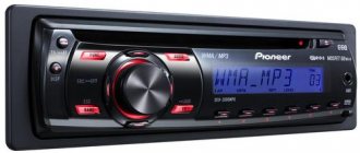
Absolutely all carburetor “eights” and “nines” were equipped with DAAZ mechanical fuel pumps produced by the Dimitrovgrad Automotive Accessory Plant. They were and are now produced under catalog number 2108–1106010.
Mechanical fuel pump DAAZ 2108–1106010
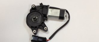
VAZ 2108/2109 injection engines were equipped with electric submersible gasoline pumps produced by Russian enterprises Pekar, Utes, SAAZ, as well as pumps of joint and foreign production. Fuel pumps were installed on the latest modifications. The catalog number of the submersible electric fuel pump VAZ 2108/2109 is 2112–1139009.
Electric pump "Bosch" 2112–1139009
Checking the cooling system
What to do if the VAZ 21099 carburetor cooling fan does not work? As soon as the car owner noticed the first signs of overheating, i.e. the temperature sensor arrow has approached the red zone, but the carburetor has not yet started pouring smoke from under the hood of the VAZ 21099, you need to check the cooling system.
Check all wire connections
Step-by-step instructions for checking the cooling system.
READ How to Disassemble the Rail of a VAZ 2109
Checking the performance of the fuel pump on injection VAZ 2108/2109
If in Sputniks and Samaras with carburetor engines, fuel pump malfunctions are associated only with its design, then in injection vehicles they can also be caused by problems with the power supply of the device.
Diagnostics of the electric circuit of the fuel pump
To check whether voltage is supplied to the fuel pump, turn on the ignition without starting the engine and listen. When you turn the key, you should first hear the click of the relay, and then the characteristic “squeal” that the electric motor of the fuel pump emits. If these sounds are absent, the search for the problem should begin with the pump circuit protection devices.
The fuel pump relay and fuse are located in an additional mounting block, which is located under the glove compartment. The pump relay (R2) is installed in the middle, and its fuse (F2) is located to the left of it.
The fuel pump relay and fuse are located in an additional mounting block under the glove compartment.
We check them in this order:
- Disconnect the negative terminal from the battery.
- We remove the fuse from the socket and test it with a tester. If it is faulty, we replace it.
- We connect the terminal to the battery and turn on the ignition without starting the engine. We switch the tester to voltmeter mode and measure the voltage between the relay output to which the pink wire fits and ground. The device should show 12 V. If there is no voltage, the problem must be looked for in the wiring or contact group of the ignition switch. If power is supplied to the relay, use a screwdriver to close the terminal to which the pink wire fits with the terminal connected to the gray wire. This way the pump circuit will be closed directly (bypassing the relay). The fuel pump is working - we change the relay, if not - we check whether voltage is supplied to the pump itself.
- We remove the back seat. We bend the carpet underneath and find the hatch. Unscrew the screws (2 pcs) securing it. There is an electrical connector under the hatch. Disconnect it from the pump. Turn on the ignition. Using a tester turned on in voltmeter mode, we measure the voltage between the “plus” (gray wire) of the pump and its “ground”. There is voltage - the problem is in the pump itself, if not - the reason should be sought in the wiring.
Checking the fuel pressure in the system
If the diagnostics show that the pump is working, but the above signs of its malfunction are observed, you need to check the fuel pressure in the system. For this you will need:
- a pressure gauge with a measurement limit of 5–7 atmospheres (a regular tire gauge will do);
- a piece of petrol-resistant hose with a length of 50 cm and an internal diameter of 10–12 mm;
- nipple cap;
- 2 hose clamps;
- dry rag.
We check the pressure in the following order:
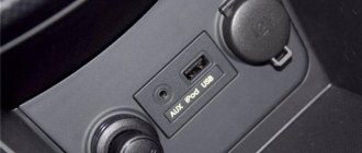
- We find a special fitting on the fuel rail. It is located on the right side of the device (when viewed from inside the car).
The fitting is located at the end of the ramp on the right side
Unscrew the spool with a nipple cap
We connect one end of the hose to the pressure gauge, the other to the fitting on the ramp
The pressure when the ignition is on should be 2.8–3.2 atmospheres
Fuses and relays VAZ 2108, 2109, 21099
Welcome! Starter activation relay - many will think at this point that we are talking about a retractor relay, in fact this is not so, in total the starter has two relays, one that turns it on and the second one that extends the bendix and pushes its gear onto the crankshaft pulley (the second is the same solenoid relay), if the first one fails (Happens occasionally mainly due to overloads on it or due to faulty wiring), you will not be able to start the starter and therefore the car will not start, if If the second one fails, the situation will be slightly different, but specifically the car may also not start and the clicking will occur when the key is turned, but this can still be said acceptable, but if this relay fails completely and does not return the bendix to its reverse position, then the following will happen, when you turn the key, the starter will begin to turn the engine of the car and eventually it will start, but when you return the key after the engine has started in the reverse position, the bendix at the starter will not turn back (the solenoid relay does not work) and In a very short time the starter will become unusable.
Note! To change the relay that is responsible only for turning on the starter, you need to stock up on: Only one “8” wrench, more for you and you don’t need to take anything, but maybe one more wrench so that, just in case, the minus terminal with Reset the battery!
1. If you carefully read the above text, you will immediately guess how to remove this relay, but we will still instruct you, find this relay in your car (the location is shown in the photo above), you see a block of wires connected to it, then disconnect it, and after it is removed and set aside, take a wrench in your hands and unscrew the relay mounting nut with it and then remove it, by the way, if the work is done in the rain or in very wet weather, or if you are simply afraid of a short circuit in the wiring (B In this case, the entire wiring will burn out and will need to be replaced), then protect yourself by disconnecting the wire from the minus terminal on the battery to do this; if you don’t understand how to do this, then study “this article”, it says everything in the first paragraph.
Note! To check whether the relay is working or not (We don’t recommend just taking a new relay, always inspect everything), you can use 2 different methods, the first is that you have to remove the cover from the mounting block and take it out from there a relay with exactly the same markings as yours, the relay goes to turn on the starter, after removing these two relays, change these two relays and try to start the car, if it doesn’t start, it means the problem is not in the relay and you need to find the problem either in the starter itself or in the ignition switch, The second method assumes that you will find a jumper wire (Indicated by a blue arrow, the wire can also be used) and bring its conclusions to the wire block, specifically to its contacts “30” and “87” (These are the lower and upper contacts of the block, take a closer look to the relay they are marked on it, or for clarity, look at the photo they are indicated by a reddish arrow, although there is a block from a completely different car, but it is actually the same and on it you can understand where these two contacts are located) if the car starts immediately (Don’t forget the jumper when it will start to start immediately, remove it) then it’s all in the relay, if not, then look further (When you do the 2nd method, do not forget to turn the key in the ignition until all the devices light up)!
Most electrical circuits are protected by fuses. Electric motors of gear motors (windshield wipers, rear window wipers (VAZ-2108, -2109), headlights - if installed) are protected by automatic reusable bimetallic fuses. The power supply circuit of the injection system (engine 2111) is protected by a fuse-link made of wire with a conductor of reduced cross-section (1 mm2).
The relay and fuse box in the VAZ 2108-09-099 (carburetor, injector) is located under the hood, in the compartment in front of the windshield on the left side.
Fuse mounting block 2114-3722010-18
| Relay/fuse no. | Decoding |
| K1 | Headlight wiper relay |
| K2 | Relay-breaker for direction indicators and hazard warning lights |
| K3 | Windshield wiper relay |
| K4 | Lamp health monitoring relay |
| K5 | Power window relay |
| K6 | Horn relay |
| K7 | Relay for turning on electric rear window heating |
| K8 | High beam relay |
| K9 | Low beam relay |
| F1-F16 | Fuses |
Fuse mounting block 2114-3722010-60
| Relay/fuse no. | Decoding |
| K1 | Headlight wiper relay |
| K2 | Relay-breaker for direction indicators and hazard warning lights |
| K3 | Windshield wiper relay |
| K4 | Relay for monitoring the health of brake lamps and side lights |
| K5 | Power window relay |
| K6 | Horn relay |
| K7 | Relay for turning on electric rear window heating |
| K8 | High beam relay |
| K9 | Low beam relay |
| F1-F16 | Fuses |
| F1-F20 | Spare fuses |
Fuse mounting block 17.3722
| Relay/fuse no. | Decoding |
| 1 (K6) | Headlight wiper relay |
| 2 (K1) | Rear window washer timing relay |
| 3 (K2) | Relay-breaker for direction indicators and hazard warning lights |
| 4 (K3) | Wiper relay |
| 5 | Contact jumpers in place of the lamp health monitoring relay |
| 6 (K10) | Heated rear window relay |
| 7 | Spare fuse |
| 8 (K5) | High beam relay |
| 9 (K11) | Low beam relay |
| 10 | Fuse |
| 11 (K9) | Engine cooling fan motor relay |
| 12 (K8) | Horn relay |
Decoding the fuses of the mounting block for VAZ 2109, 2108, 21099
F1-F16 - mounting block 2114-3722010-60, 2114-3722010-18.
Numbers from 1 to 16 - old-style mounting block 17.3722
| Fuse N | Decoding |
| 1 (8 A), F9 (7.5 A) | Right fog lamp |
| 2 (8 A), F8 (7.5 A) | Left fog lamp |
| 3 (8 A), F1 (10 A) | Headlight cleaners (at the moment of switching on). Relay for turning on headlight cleaners (contacts). Headlight washer activation valve |
| 4 (16 A), F7 (30 A) | Headlight cleaners (in operating mode). Relay for turning on headlight cleaners (winding). Heater fan motor - heater fuse Window washer motor. Rear window wiper motor. Rear window washer timing relay. Valves for turning on the windshield and rear windows. Relay (winding) for turning on the electric fan of the engine cooling system. Relay (coil) for turning on the heated rear window. Rear window heating indicator lamp. Glove compartment lamp |
| 5 (8 A), F16 (15 A) | Direction indicators and relay-interrupter for direction indicators and hazard warning lights (in turn indication mode). Turn signal indicator lamp. Rear lights (reversing lamps). Gearmotor and windshield wiper activation relay. Generator excitation winding (when starting the engine). Brake fluid level warning lamp. Oil pressure warning lamp. Carburetor air damper warning lamp. Parking brake warning lamp. "STOP" light display lamp. Coolant temperature gauge. Fuel level indicator with reserve warning lamp. Voltmeter |
| 6 (8 A), F3 (10 A) | Rear lights (brake lamps). Interior lighting |
| 6 (8 A), F6 (30 A) | Power windows for front doors. Power window relay |
| 7 (8 A), F10 (7.5 A) | License plate lights. Engine compartment lamp. Instrument lighting lamps. Indicator lamp for external lighting. Heater lever illumination display. Cigarette lighter lamp |
| 8 (16 A), F5 (20 A) | The electric motor of the engine cooling system fan, and its activation relay (contacts). Sound signal and relay for its activation |
| 9 (8 A), F10 (7.5 A) | Left headlight (side light). Left rear light (side light) |
| 10 (8 A), F11 (7.5 A) | Right headlight (side marker). Right rear light (side light) |
| 11 (8 A), F2 (10 A) | Direction indicators and hazard warning relay-breaker (in hazard warning mode). Hazard warning lamp |
| 12 (16 A), F4 (20 A) | Rear window heating element. Relay (contacts) for turning on the heated rear window. Plug socket for portable lamp. Cigarette lighter |
| 13 (8 A), F15 (7.5 A) | Right headlight (high beam) |
| 14 (8 A), F14 (7.5) | Left headlight (high beam). Indicator lamp for high beam headlights |
| 15 (8 A), F13 (7.5 A) | Left headlight (low beam) |
| 16 (8 A), F12 (7.5 A) | Right headlight (low beam) |
Diagram of the mounting fuse block for VAZ 2109, 2108, 21099 (block 17.3722)
(the outer number in the designation of the wire tip is the number of the block, and the inner number is the conventional number of the plug)
| Relay/fuse no. | Decoding |
| K1 | Rear window washer timing relay |
| K2 | Relay-breaker for direction indicators and hazard warning lights |
| K3 | Wiper relay |
| K4 | Lamp health monitoring relay (contact jumpers are shown inside, which are installed instead of the relay) |
| K5 | High beam relay |
| K6 | Relay for turning on headlight cleaners |
| K7 | Power window relay |
| K8 | Horn relay |
| K9 | Engine cooling fan motor relay |
| K10 | Heated rear window relay |
| K11 | Low beam relay |
Diagram of the mounting fuse block for VAZ 2109, 2108, 21099 (2114-3722010-60)
| Relay/fuse no. | Decoding |
| K1 | Headlight wiper relay |
| K2 | Relay-breaker for direction indicators and hazard warning lights |
| K3 | Windshield wiper relay |
| K4 | Lamp health monitoring relay |
| K5 | Power window relay |
| K6 | Horn relay |
| K7 | Heated rear window relay |
| K8 | High beam relay |
| K9 | Low beam relay |
| F1-F20 | Fuses |
- Ignition switch wires 2108, 2109, 21099
- Pinout of the ignition switch VAZ-2109
- Ignition switch diagram for VAZ 2109 (carburetor, injector): photo Ignition switch diagram
- Types of the castle
- headlight cleaner relay (K6);
- rear window washer relay (K1);
- turn signal and hazard warning relay (K2);
- windshield wiper relay (K3);
- contact jumpers;
- rear window heating relay (K10);
- spare fuse;
- headlight high beam relay (K5);
- low beam headlight relay (K11);
- fuse;
- radiator cooling fan relay (K9);
- horn relay (K8);
- K1 – rear window washer relay;
- K2 – turn signal and hazard warning relay;
- K3 – windshield wiper relay;
- K4 – lamp serviceability relay;
- K5 – high beam headlight relay;
- K6 – headlight cleaner relay;
- K7 – power window relay;
- K8 – sound signal relay;
- K9 – Cooling system fan relay;
- K10 – rear window heating relay;
- K11 – Low beam headlight relay.
- K1 – headlight cleaner relay;
- K2 – turn signal and hazard warning relay;
- K3 – windshield wiper relay;
- K4 – lamp serviceability relay;
- K5 – power window relay;
- K6 – sound signal relay;
- K7 – rear window heating relay;
- K8 – high beam headlight relay;
- K9 – low beam relay;
- F1-F20 – fuses.
Fuel pump VAZ 2109 injector
The fuel pump on the VAZ injector is installed electric. That is, it is turned on by supplying +12V voltage from the battery to it. It is located in the gas tank of the car. The task of the fuel pump is to supply fuel under pressure into the fuel rail, from where it is sprayed directly into the working cylinder using the injection system. Checking the functionality of the fuel pump: 1) When the ignition is turned on, the pump should start working. That is, the sound of its operation should be heard in the rear seat area. Therefore, the very first thing you need to do is check the fuse and the fuel pump relay. The assignments of the relays and fuses are labeled on the back of the mounting block cover. If the fuse is intact and the relay is working properly, then you need to remove the back seat of the car and measure the voltage at the fuel pump itself. This is done using a multimeter or wires with a 12V light bulb.
If there is voltage at the pump, then everything is fine with the electrical part; you need to look at the fuel system. If voltage is not supplied to the fuel pump, you need to check the wire from the mounting block to the fuel pump; it may be damaged. 2) On the VAZ 2108 2109 21099 injector, it is not recommended to allow the fuel level in the tank to be less than 10 liters. Not the most convenient requirement, given that the car’s gas tank capacity is 45 liters. However, there is a reason for this: if the fuel level in the gas tank is low, the gas pump may catch air, which is unacceptable.
The operation of the pump is checked by measuring the pressure in the fuel rail. The rail has a special hole for connecting a pressure gauge. If there is voltage to the pump, but there is no pressure in the fuel rail, you need to check the fuel filter. If it is in order, check the fuel line from the tank to the ramp; if it is also not damaged, then the fuel pump is most likely faulty.
For further diagnostics, you need to remove the fuel pump from the car and try to install a new one. If everything works with the new fuel pump, then the old pump is faulty. If, even with a new fuel pump, there is no pressure in the fuel rail and the car does not start, then the problem will be in the fuel system.
If you do not have a pressure gauge, the operation of the gas pump can be checked by the amount of fuel pumped per unit of time. Having unscrewed the spool, we connect a hose to the ramp, which we lower into the container for measurement. On Kalina and Grant, the pump should pump 35 liters per hour, or 0.5 liters. in a minute. At ten, the pump pumps 1 liter. in a minute. If much less fuel has leaked out, all filters must be checked. Under the bottom, next to the gas tank, there is a high-pressure filter. Another filter that needs to be checked is located in the tank itself on the fuel module
What to pay attention to: To remove the fuel pump from the car, you must remove the fuel tank. The VAZ 2108 2109 21099 fuel pump cannot be removed directly from the passenger compartment, the injector cannot be removed, you can only check the voltage supply to it
Signs and Symptoms of a Bad Fuel Pump Relay
Let's start with the fact that the fuel pump is controlled through a relay according to the following general scheme:
- the driver inserts the key into the lock and turns on the ignition;
- after turning on the ignition, the relay turns on the fuel pump for 2-3 seconds, which is necessary to create pressure in the fuel rail.
- then you can hear a characteristic sound as the fuel pump relay clicks, which has turned off the fuel pump;
- subsequent operation of the fuel pump will be possible under 2 conditions: rotation of the engine by the starter during startup and further independent operation of the already running engine.
- after turning off the ignition and stopping the engine, the relay turns off the fuel pump immediately or after 1 second.
Also on some cars the device serves as a kind of engine speed limiter. If the engine speed approaches maximum and begins to exceed the permissible threshold, the fuel pump is switched off via a relay. The gasoline supply stops, the speed decreases, after which the element supplies power to the pump again.
It should be additionally noted that on some vehicle models the fuel pump does not turn on after turning the key in the ignition, but at the moment the driver's door is opened. This solution allows you to quickly start the engine, as it ensures that the necessary operating pressure is created in the fuel system in advance. In other words, the pump pumps gasoline until the driver decides to insert the key and start the engine.
We also recommend reading the article about what to do if the starter clicks but does not turn the engine. From this article you will learn about the main causes of this malfunction, as well as how to check the starter yourself.
If the relay malfunctions, then power may not be supplied to the fuel pump. The second option is that the pump hums or hums constantly, that is, it does not turn off a few seconds after the required pressure is created in the fuel line. In the first case, the engine often cannot be started because the pump does not pump and there is no gasoline in the fuel rail. In the second case, the fuel pump relay gets stuck (the fuel pump relay does not work) and the battery charge is consumed for the constant rotation of the fuel pump motor. Let us add that on some cars, starting the engine is possible even if there are certain malfunctions in the operation of the element, since the pump relay connection diagram allows the device to operate while the starter is cranking.
Mechanical fuel pump repair
The functionality of a mechanical fuel pump can be restored by replacing its faulty elements. You can buy them at any automobile store. But it is better to buy not individual spare parts, but a repair kit. It includes all the elements that can fail:
- intake and exhaust valves;
- diaphragms with spacers, “plates”, rod;
- pusher;
- thermal spacer;
- gaskets
Replacing valves
To replace the pump valves you will need a slotted impact driver and a small hammer. The valves are held in their seats by punching at three points. These areas must be carefully knocked off with a screwdriver. After this, the valves can be removed. Having installed the new parts, we secure them with cores. To do this, place the tip of the screwdriver on the edge of the housing along the circumference of the socket and strike it lightly with a hammer. We fix each valve in three places.
Replacing valves
How to change apertures
To replace the diaphragms, you need to unscrew the nut by 10 in the upper part of the rod. Next, we remove the damaged elements, and in their place we install parts from the repair kit.
The kit includes three diaphragms: two working and one safety. The latter serves to prevent unauthorized fuel from entering the carburetor if the first two are damaged. It is installed at the very bottom of the rod immediately after the lower “plate”. We place spacers on top of it on the rod: first a small one, then a large one. We place the working membranes and the upper “plate” on them. We secure the resulting structure with a nut.
The mechanical fuel pump has 3 diaphragms
Replacing the pusher, thermal spacer and gaskets
The thermal spacer does not need to be replaced unless it is damaged. Inspect its mating surfaces, especially the outer one, to which the lower part of the pump housing is attached. It should be perfectly smooth. Otherwise, oil leakage may occur at the junction of parts during engine operation.
Replacing the pusher is carried out by removing the old one and installing a new rod in its place. There is no difference in which end where it will be installed.
Now about the gaskets. There are only three of them in the repair kit, and they have different thicknesses:
- “A” – 02.27–03 mm;
- “B” – 0.7–0.8 mm;
- “C” – 1.1–1.3 mm.
The first is intended for installation between the thermal spacer and the auxiliary drive housing, and the gaskets “B” and “C” are used to adjust the protrusion of the pusher above its mating surface.
The adjustment is made as follows:
- We install the thermal spacer with the first gasket and a new rod into the auxiliary drive housing.
- Place gasket “B” on the mating plane of the spacer. Next, you need to rotate the engine crankshaft to the position of the pusher until it is recessed as much as possible. This can be done using a large slotted screwdriver. We insert its end into the clutch housing window and slowly push the flywheel clockwise.
- We periodically check the position of the pusher and measure its protrusion. When it enters the auxiliary drive housing to its maximum length, we measure how much it protrudes above the mating plane of the spacer with the gasket already installed on it. This value should be 0.8–1.3 mm. If it is larger, replace gasket “B” with gasket “C”. If the protrusion length is less than specified, swap gaskets “A” and “B”.
After the adjustment is completed, the fuel pump is installed in place and secured with nuts.
Optimal indicator values for the fuel pump
To determine faults in the pumping system, you must know exactly the exact characteristics of this device. It is shown in this table.
| Characteristic | Options |
| Fuel pump rod length | 82.4 ml |
| Protrusion of the rod above the top gasket | 0.8-1.3 ml |
| Thickness of the first gasket | 0.3 ml |
| Fuel pump rod stroke | 2.5-2.8 ml |
| Pump pressure at idle speed | 0.20-0.35 atmospheres |
Of course, a new fuel pump is not that expensive (the average price is 800-900 rubles), but often the old fuel pump is still usable, you just need to buy a few penny parts and tinker for a couple of hours.
Where is the fuel pump relay located?
The location depends on the specific make and model of the car, but usually this part is located under the hood or next to the KE control unit. There are as many as three installed, they are located in the fuse block. The top one is the main one, the middle one refers to the electric motor of the cooling system, and the bottom one is connected to the fuel pump. In VAZ cars it can be found in the area of the left leg of the passenger sitting next to the driver.
Possible diagnostic methods are discussed in the table:
Methods for diagnosing the fuel pump relay
Purpose of inspection
Peculiarities
Determination of pressure in the fuel system
How to check a mechanical fuel pump VAZ 2108/2109
Checking a mechanical fuel pump involves determining its performance, i.e. measuring the amount of fuel pumped per unit of time. And according to the characteristics of the device, it should be at least one liter per minute. To determine it, you will need an assistant, as well as the following tools and tools:
- screwdriver with Phillips bit;
- a piece of fuel hose;
- 2 empty plastic bottles;
- 1.5 liters of gasoline;
- watch with stopwatch.
Sequencing:
- Using a screwdriver, unscrew the screw on the outlet fitting clamp, loosen it and remove the fuel hose.
- Pour gasoline into a plastic bottle. We lower the free end of the fuel hose (removed from the outlet fitting) into the bottle to the bottom. Through it, gasoline will be sucked into the carburetor when the fuel level in the float chamber decreases.
- We put the end of the prepared hose onto the outlet fitting of the fuel pump. Place the other end into an empty bottle.
- We ask the assistant to start the engine, start the stopwatch. If the car has a tachometer, stick to 2000 rpm. If it is not there, we rely on hearing.
- When the engine starts, gasoline should flow from the pump outlet into the container. After a minute has passed, ask the assistant to turn off the engine and measure the amount of gasoline pumped. If the volume of fuel in the bottle is less than a liter, the fuel pump must either be repaired or replaced.
Further diagnostics should be aimed at identifying the faulty pump element. To carry it out you need:
- screwdriver with Phillips bit;
- wrenches 10 and 13;
- caliper (ruler).
Check procedure:
- First of all, we check the operation of the valves. Unscrew the screws of the clamps securing the fuel hoses to the pump fittings. We remove the hoses. We put our finger (palm) against the outlet fitting, plugging it. Press the manual pumping lever several times. At the same time, the pump should make slurping sounds, and air pressure should be felt at the fitting. We check the intake valve in the same way. When you press the pumping lever, your finger should be sucked into the fitting. If there is neither pressure at the outlet nor vacuum at the inlet, either the valves or the diaphragms are faulty.
- At the next stage, use a 10mm wrench to unscrew the fuel pump cap. There is a mesh filter underneath. We assess his condition. The mesh must be clean and have no signs of deformation. If necessary, you can clean it with a jet of air, an old toothbrush and gasoline.
- Now let's check the apertures. Unscrew the screws securing the upper and lower parts of the housing. There are only 6 of them. Remove the body and remove the rod with the diaphragms. There is a nut at the top of it. We unscrew it with a 10mm wrench, remove and disconnect the diaphragms. We assess their condition. If they have ruptures or cracks, the diaphragms need to be replaced. They are unsuitable for further use.
- The last step is measuring the length of the pusher. To get to it, you need to disconnect the lower part of the pump housing from the accessory drive housing. Unscrew the two nuts with a 13mm wrench and remove the lower part. Under it there is a textolite thermal spacer in the form of a cone, the top of which goes into the drive housing. There should be thin paronite gaskets on its mating surfaces. Remove the spacer with gaskets. There is a pusher inside it. We take it out and measure the length. It should be 82.5 mm (minimum acceptable - 81.8 mm). If the pusher is worn, it needs to be replaced. Wear leads to a decrease in the amplitude of movement of the rod with diaphragms, due to which its performance is significantly reduced.
Tips for motorists
VAZ-2109 passenger cars of the last years of production had injection engines, so on these “nines” an electric fuel pump was installed in the fuel tank. And on a small part of the VAZ-2109 with a carburetor engine still in use today, mechanical fuel pumps were installed.
Failure to operate the fuel pump on VAZ-2109i injection engines is determined quite simply, since when the ignition key is turned to the “ignition on” position, the driver simply will not hear the characteristic noise that the running electric motor of the fuel pump makes. Typically, drivers of “nines” begin their search for the cause of a fuel pump failure by checking the condition of the fuse that protects this electrical circuit.
It is located under the front panel shelf, which is located below the glove compartment. When you unscrew the fastening screws, the block of three relays and three fuses on the wires will move lower, so it will be more convenient to work with it. You will need to check the rightmost fuse and the condition of its contacts. If a blown fuse is detected, it will have to be replaced with a new one. And also find the reason why he burned out.
If the fuse is intact and the contacts are not oxidized, then the next step in troubleshooting is to check the functionality of the fuel pump relay. It is located in the same block as the fuse and is located on the far right. Drivers usually check it by replacing it with a known-good relay. If after such a replacement the fuel pump starts working, then you will have to purchase and install a new relay.
But when the fuel pump still continues to be “silent”, then you will need two wires four meters long. They are needed to check the condition of the fuel pump itself by connecting it to power directly from the battery. To do this you will need to: lift the rear seat cushion, remove the hatch cover, disconnect the plug block and connect the wires from the battery to the fuel pump terminals. There are three terminals in the block: one for ground, the negative one from the battery is connected to it, two more positive ones, for the fuel pump and the fuel level indicator in the tank.
If the fuel pump, when connected directly, works, then you will have to ring the wires going from it to the fuel pump relay, and if it does not work, then either replace it with a new one, or you will have to disassemble it and look for a fault inside the fuel pump.
On “nines” with a mechanical fuel pump, the most common malfunction is wear of the fuel pump diaphragm, as a result of which gasoline will leak through the drainage hole in the housing when it operates. The second reason for the failure of such a fuel pump is wear of the pusher, which transmits force from the camshaft cam to the fuel pump drive lever.
Checking the general condition of the fuel pump
First of all, let’s check whether the supply system of your VAZ 2109 is working at all. To do this, you need to take the following steps:
- Remove the pump fuel hose from the source or discharge fitting;
- Manually press the fuel pump lever several times;
- If the pump is operational, a strong stream of fuel will immediately flow through the fitting;
- If there is no jet or it is very weak, it will be necessary to carry out other checks.
Intake Valve Check
- Disconnect the hose from the suction fitting so that both hoses are eventually removed, each from its own fitting.
- Simply plug the suction fitting with your finger, then pull the lever several times to manually pump fuel. If everything works fine, your finger will begin to be sucked into the fitting. This effect indicates that the pump is working properly. Therefore, we look for the problem in the tank or lines.
- If there is no suction, you will have to disassemble the device to replace the inlet valve. Its tightness is most likely broken.
Leak test
To check the tightness of the intake valve, you must:
- Place your finger on the hole from the injection fitting and pump up the fuel several times using manual pumping;
- In this case, a stream of air should come out of the hole, significantly repelling the pressed finger;
- If the stream turns out to be weak or does not exist, the fuel pump simply does not pump.
In this situation, there are two options - look for the problem inside the fuel pump device, disassembling the pump, or change the entire unit.
The filter is clogged or damaged
To fix the situation, you need:
- Remove the cover from the fuel pump, remove the filter, clean and rinse it with clean fuel. Then be sure to blow out with compressed air;
- Check the condition of the filter. If it is deformed, no repair will help. You will have to change the filter device;
- If you have a Pekar pump or a similar one, the filter can be removed by unscrewing the suction fitting from the cover. That is, it is not necessary to remove the cover at all.
Pump diaphragm failure
You need to do the following for your fuel pump:
- Remove the upper part of the fuel pump housing and remove the diaphragm assembly from there;
- Unscrew the nut on the rod, and then pull out the 3 diaphragms;
- Replace faulty elements with new ones. They are available in any repair kit for the VAZ 2109 fuel pump;
- Reassemble the assembly in reverse order;
- If you have a Pekar pump, there is only one diaphragm. It can be removed by removing the cover;
- To disconnect the diaphragm assembly, rotate it 90 degrees.
Be sure to simultaneously check the condition of the spring located under the diaphragm. To do this, you need to remove the upper part of the pump housing, remove the diaphragm rod and look at the current state of the spring. If it is broken, deformed or lacks elasticity, replace the element.
Intake and exhaust valve malfunctions
If both valves raise doubts about their functionality, certain measures will have to be taken.
- Remove the cap from the fuel pump and remove the strainer.
- Visually assess the condition of the pump cavity and inlet valve.
- With the top of the pump body removed, you can take a look at the outlet valve.
- If both valves are not installed tightly enough, they are not pressed well or have become motionless, replace the entire pump completely.
- If you find traces of clogged valves, remove them and blow out the housing with compressed air.
In the case of the Pekar pump, two valves are located in the cover, so to assess their condition, simply remove the cover from the fuel pump housing.
Damage to the pusher
It is not uncommon for a fuel pump to fail to operate due to damage to the pusher. We have prepared separate instructions for this case.
- Remove the pump from the studs by unscrewing the fastening nuts. The thermal insulation insert, pusher and gaskets remain on the motor.
- Rotate the crankshaft to extend the pushrod as far as possible.
- Measure the distance that the pusher protrudes relative to the top gasket. Normally, the figure is 0.8-1.3 millimeters.
- If the protrusion is smaller or larger, try adjusting it using thicker or thinner shims.
- Between the thermal insulation insert and the pump there is an external gasket with the greatest thickness. It is this that needs to be changed when adjusting the protrusion.
- New gaskets are available in repair kits, although many make their own. To do this you will need a piece of paronite.
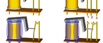
Design and operating principle
When an electric current passes through the coil, an electromagnetic field is created, under the influence of which the armature moves inside the core. When the power is cut off, the field disappears and the armature begins to move freely along the core.
The ignition relay includes the following components:
- Electromagnet;
- Anchor;
- Return spring;
- Contacts;
- A pair of windings.
The electromagnet, in turn, includes two coils in its design.
| Coil type | Peculiarities |
| Holding reel | It is connected to the ignition relay housing, as well as the control output |
| Retractor coil | The retractor coil is connected to the motor contact as well as the control terminal |
Device location
The operating principle of the node is based on the following:
- When voltage is applied to the control contact, electric current begins to flow through the coils. This leads to the appearance of an electromagnetic field, under the influence of which the armature moves, compressing the return spring;
- The armature also moves the bendix, then the rod, which closes the contacts connecting the battery with the starter motor;
- When the contacts are closed, a plus is supplied at the output of the retractor coil, which moves to the motor output. So the current stops passing through it - the magnetic field disappears, but the armature remains in the retracted position due to the influence of the magnetic field from the holding coil;
- The armature returns to its original position after the engine is started and the power is turned off, which occurs under the action of the return spring;
- In this case, the contacts open, the bendix is disengaged;
- The contacts of the retractor relay are bolts that are installed in the textolite cover, as well as plates (can be round or rectangular). They close the bolts when the armature moves.
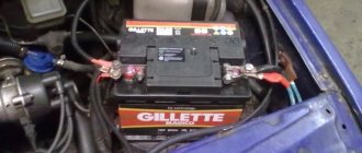
Where is the mass of the VAZ-21099 injector (main)
If the starter turns weakly, or the engine does not start at all (clicks occur when starting), various electrical problems arise, it is likely that the car does not have normal weight. Fixing such a problem is generally not difficult, but to do this you still need to know where the mass of the VAZ-21099 injector is located.
The main mass (thick) wire goes from the negative terminal of the battery to the engine, the thinner wire is connected to the car body, all energy consumers in the car depend on this connection. If the contact is poor, the battery stops charging normally; in order for the starter to turn well, you should check the reliability of these contacts and clean the metal from oxidation. If, due to a heavy load (for example, when installing additional equipment), the ground wire heats up and there is clearly not enough of it, you can “lay” additional ground almost anywhere where good contact between the engine and the body is ensured. The main thing is that this wire has a sufficient cross-section.
Fan diagnostics
In order to check the operation of the unit, you will need a one and a half meter wire, preferably with “crocodiles” at the ends. With the engine off, connect the positive terminal of the battery directly to the fan terminal. The working unit should begin to rotate. If not, then this is a malfunction. If the cooling fan does not turn on when the engine overheats, although diagnostics show that they are working, you should check the DTOZH.
During the test, you will need an ohmmeter to measure the resistance of the sensor. An ohmmeter is included in any, even the simplest portable digital multimeter. The procedure is as follows:
READ Turn signals do not work VAZ 2107 injector
If for some reason the sensor resistance is not normal, the part must be replaced. And if this is the case, but the unit does not turn on, something is not working in the electronic engine control unit. You should contact a service station. You will need special equipment to diagnose and flash your computer.
Pump operating principle
The VAZ 2109 fuel pump has a fairly simple design; the injector functions only thanks to it. It is based on two elements - an electric motor and a pump with a filter element.
Please note that the “diaper” (as people call the filter due to its similarity) needs to be changed on time - try not to let it work for more than 20 thousand km
Otherwise, it becomes saturated with metal shavings, dirt and other rubbish, which gets into the line and clogs the injectors.
The fuel rail contains a mixture of gasoline and air (also purified, by the way). The proportion is always the same - 14 parts of air and one part of gasoline. This is the ideal mixture for combustion to occur.
But you need to pay attention to the fact that the VAZ 2109 fuel pump relay, which is controlled by an electronic unit, is involved in the operation. It is used to supply power to the pump motor.
The pump's performance is high, so the engine does not run constantly, but intermittently (and depending on the operating mode of the engine, the pauses between starts may be different).
For control, there is a pressure regulator installed on the ramp. To drain excess gasoline - a check valve. With its help, all excess gasoline flows back into the tank. The VAZ 2109 fuel pump (injector) is removed if it is being repaired or replaced. The following tools will be useful:
- Pliers.
- Keys for “6”, “8”.
- Phillips and flathead screwdrivers.
Raise the lower part of the seat, opening the rear doors completely. Unscrew the screws securing the plastic cover. Disconnect the power supply and connection to the level sensor. Loosen the clamps and remove the hoses
Please note that the pressure in the system must be reduced in advance. Using an “8” wrench, unscrew all the nuts that secure the pump to the tank body. Carefully remove the pump from the hole. The main thing in this matter is accuracy, as there is a risk of damaging the fuel level sensor
And one more thing: before removing the VAZ 2109 fuel pump, you need to get rid of dirt and dust. Therefore, blow the installation area with compressed air or at least clean it with a brush
The main thing in this matter is accuracy, as there is a risk of damaging the fuel level sensor. And one more thing: before removing the VAZ 2109 fuel pump, you need to get rid of dirt and dust. Therefore, blow the installation area with compressed air or at least clean it with a brush.
To verify the serviceability (or malfunction) of the fuel injection pump of the VAZ 2109, just remove it and connect it directly to the battery. If it works normally, without any extraneous sounds (and air pressure is felt from the outlet), then there are no problems with it. But if it does not turn on even this way, you should think about replacing it. The price of a new one will be about 2000 rubles. Is it worth repairing an electric motor? It is unlikely that this will improve the situation for a long time, but as a temporary solution it is quite normal. But you can do this procedure only if you are confident in your abilities and have an understanding of how electric motors work.
The gasoline pump in the fuel system of a carburetor engine is responsible for the uninterrupted supply of fuel from the fuel tank to the carburetor. Accordingly, the main signs that indicate a malfunction in its operation are associated with a deterioration in fuel supply, which in turn can manifest itself either in poor starting of a cold engine, the appearance of interruptions during its operation at different crankshaft speeds, etc. Before proceeding with disassembly and repair, it is necessary to check the fuel pump, and to do this we will perform the following sequence of actions:
• Loosen the fastening clamp and remove the hose from the pump discharge pipe. The discharge pipe is the one that is located closer to the carburetor in the direction of fuel supply in the line.• After removing the hose, begin to pump the fuel pump handle. The fuel pump handle only works at a certain position of the crankshaft, so if the pump does not pump, try turning the crankshaft half a turn and try again. Fuel under pressure must be supplied through the pipe. If the fuel stream is weak or does not flow at all, loosen the clamp and remove the hose from the suction pipe.
• Close the suction pipe with your finger and pump the fuel pump. A vacuum should be created in the pipe, which you can feel with your fingertip. If a vacuum is not created, then it is necessary to remove and repair the fuel pump or completely replace it with a new one.
Malfunctions
As practice shows, when the relay is in a faulty state, the engine will not start. There are two main types of fault:
- When electricity is not supplied to the relay through the electronic control unit. In this case, the engine will not be able to start due to lack of pressure in the fuel system.
- The relay is stuck in the on position when the ignition is turned on. The engine cannot be started. But since the fuel pump motor is always on, battery power will be consumed. Such a malfunction can lead to failure of the fuel pump motor or battery. This will lead to additional costs, like mine.
So, if your battery is draining or your engine won't start at all and you can't find the cause of the problem, check your fuel pump relay.
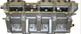
Pump repair and complete replacement
First, you need to remove the car's air filter. Next, disconnect the fuel supply hose with gasoline and the hose that goes directly to the carburetor. After this, unscrew the nuts that secure the pump to the engine block and remove it. Disassemble the pump as carefully as possible to avoid damaging the diaphragm. Check carefully to see if there are any cracks or heavy contamination in its parts.
You can buy a repair kit for a carburetor-type mechanical pump at any auto store. After installing and replacing parts, the pump must be washed with gasoline and purged under pressure. Regardless of the nature of the failure, be sure to replace the gaskets in the pump before reassembling.
The design of the fuel pump of an injection car is such that it cannot be repaired, so a complete replacement is usually required. To replace the fuel pump in a fuel-injected car, you need to lift the back seat and find the hatch under the trim. Carefully remove its cover, disconnect all electrical chips, having first removed the battery terminals. Next, unscrew the nuts and pull out the housing with the pump. It is best to replace the strainer before installing a new pump. Reassemble everything in reverse order and connect the terminals on the battery.
Home →
Maintenance and Repair → Repair →
CORRECT DISASSEMBLY AND REPLACEMENT PROCEDURE
In order to properly remove the fuel pump, you must perform the following sequence of actions:
Buy a repair kit right away. Remove the air filter and its housing. Disconnect the gasoline supply and return hoses from the fuel pump fittings. Unscrew the nuts that secure it. Remove it carefully so as not to damage the gaskets. After this, inspect each part for cracks, check all its valves for leaks. Make sure that the discharge and suction fittings remain motionless in their sockets. The diaphragms must be free of peeling and ruptures. The filter must be absolutely clean and undamaged. Wash all filter parts with gasoline and then rinse with a compressor. Replace all damaged parts, it is also recommended to install a new pump gasket. When installing the gasket, apply Litol-24 type lubricant to its surface. If the housing is damaged or there is other irreparable damage to important parts, the pump will have to be completely replaced. Then you need to move on to installing the pump in place. In this case, you should immediately adjust its supply using spacers. To do this, you need to measure the protrusions of the pusher. If the protrusion is too strong, the gasoline pressure will be increased, which will easily break the carburetor shut-off valve. If the distance is lower than required, when the load increases and the vehicle speed increases, insufficient gasoline will flow into the carburetor. Install the gasoline pump in reverse order. Make sure that the arrow located on the body points towards the carburetor. When installing the diaphragm unit, the holes in its gasket should be located away from the muffler pipe.
Thus, you have outlined detailed instructions for removing and disassembling the fuel pump, which will help you carry out this operation yourself. You can finish here, you shouldn’t have any difficulties.
Pinout of fuel pump VAZ 2107
1 – radiator fan drive motor; 2 – mounting block block; 3 — idle speed sensor; 4 – engine ECU; 5 – potentiometer; 6 – set of spark plugs; 7 – ignition control unit; 8 – electronic crankshaft position sensor; 9 – electric fuel pump; 10 – indicator of the number of revolutions; 11 – lamp for monitoring the health of electronic systems and the brake system; 12 – ignition system control relay; 13 – speedometer sensor; 14 – special factory connector for reading errors using the BC; 15 – injector harness; 16 – adsorber solenoid valve; 17, 18, 19,20 – fuse box for repairing the mounting block that protects the injection system circuits; 21 – electronic fuel pump control relay; 22 – electronic relay for controlling the exhaust manifold heating system; 23 – exhaust manifold heating system; 24 – fuse protecting the heater circuit; 25 – electronic air sensor; 26 – coolant temperature control sensor; 27 – electronic air damper sensor; 28 – air temperature sensor; 29 – pressure control sensor and low oil pressure lamp.
In the absence of one, this can be done by disconnecting the connection block for the fuel pump and fuel level control and applying voltage with wires from the battery to the place where the gray wire is connected +12 and to the place where the black wire is connected - minus. A humming pump will indicate a faulty fuse, power circuit or ECU.